Ruskinn Concept 400 UM-018 User manual

UM-018
Concept 400 End User Manual

Concept 400
UM-018 Version 1.4 2 Concept 400 end user manual
Contents
1. Overview 6
1.1 Safety instructions 6
1.2 Regulatory compliance 7
1.3 Symbols 7
1.4 Installation and relocation 8
1.5 Weight and dimensions 9
2. Gas and electrical supply requirements 10
2.1 Gas supply requirements 10
2.2 Gas regulator requirements 10
2.3 Electrical supply requirements 10
2.4 Voltage and frequency requirements 10
2.5 Power consumption 10
2.6 Powering the workstation 11

Concept 400
UM-018 Version 1.4 3 Concept 400 end user manual
3. Workstation overview 12
3.1 Workstation layout 12
3.2 Component layout 12
3.2.1 Front view –standard front 12
3.2.2 Front view –removable front 13
3.2.3 Rear view 14
3.2.4 Left side view –Standard humidifier 15
3.2.5 Left side view –Ultrasonic humidifier 16
3.2.6 Right side view 17
3.2.7 Right side view –Jar attachment option 18
3.3 Control system layout 19
3.3.1 Control panel –Standard humidity control 19
3.3.2 Control panel –Ultrasonic humidity control 21
3.3.3 Temperature controller / ultrasonic humidity controller 23
3.3.4 Port selector knob controller 23
3.3.5 Interlock inner door control panel 24
3.3.6 Foot switch control panel 24
3.3.7 Power entry panel 25
3.3.8 Power entry panel –jar attachment option 25
3.3.9 Jar attachment option control panel 26
4. Temperature and humidity control 27
4.1 Temperature control 27
4.2 Humidity control 27
4.2.1 Standard humidity control 27
4.2.2 Ultrasonic humidity control 28
5. Environmental gas composition control 29
5.1 Environmental control overview 29
5.2 Using the anaerobic indicator strips 29

Concept 400
UM-018 Version 1.4 4 Concept 400 end user manual
5.3 Gas excess system 30
5.4 Auto gas change system 30
6. Using the workstation 31
6.1 Commissioning cycle 31
6.2 Using the interlock 32
6.2.1 Interlock overview 32
6.2.2 Opening the interlock outer door 32
6.2.3 Opening the interlock inner door 32
6.2.4 Transferring material into the workstation chamber via the interlock 33
6.2.5 Removing material from the workstation chamber via the interlock 33
6.3 Hand access to the main chamber 34
6.3.1 Ezee Sleeve TM overview 34
6.3.2 Entering the workstation using the Ezee Sleeves TM 35
6.3.3 Exiting the workstation using the Ezee Sleeves TM 36
6.3.4 Arm gas displacement volume and pressure changes 37
6.4 Single Plate Entry System (SPES) 37
6.4.1 SPES overview 37
6.4.2 Using the SPES 38
6.5 Internal lights 39
6.6 Rear shelf 39
6.7 Optional extras 39
6.7.1 Cable gland 40
6.7.2 Gas sample port 40
6.7.3 Vacuum port 41
6.7.4 Internal power socket 41
6.7.5 Jar attachment option 42
6.8 Online video user guides 42

Concept 400
UM-018 Version 1.4 5 Concept 400 end user manual
7. Cleaning and maintenance 43
7.1 Cleaning the workstation 43
7.1.1 Cleaning agents 43
7.1.2 Cleaning procedure –during and after each use 43
7.1.3 Removing/ reinstalling the front screen (optional extra) 44
7.1.4 Cleaning procedure –deep clean 44
7.2 Maintaining the workstation –End user maintenance 46
7.2.1 Filling the pressure relief/ humidifier tank 46
7.2.2 Replacing an Ezee Sleeve TM 47
7.2.3 Replacing the detox and catalyst sachets 48
7.2.4 Replacing the mains plug fuse –UK users only 49
7.2.5 Replacing the mains fuses 50
7.3 Service requirements 51
7.4 Spare parts and accessories 51
7.4.1 Overview 51
7.4.2 Spare parts and cleaning agents 52
7.4.3 Accessories 53
7.5 Workstation malfunction 54
7.6 Common problems and solutions 55
7.6.1 Workstation general problems 55
7.6.2 Interlock problems 57
7.6.3 Gas consumption/ environmental control problems 58
8. Warranty information 60
9. Disposal information 61
10. Contact details 62

Concept 400
UM-018 Version 1.4 6 Concept 400 end user manual
1. Overview
Congratulations on the purchase of your Ruskinn Technology Limited Concept 400 workstation.
Please read this manual carefully to familiarise yourself with the operation and maintenance of your
Concept 400 workstation.
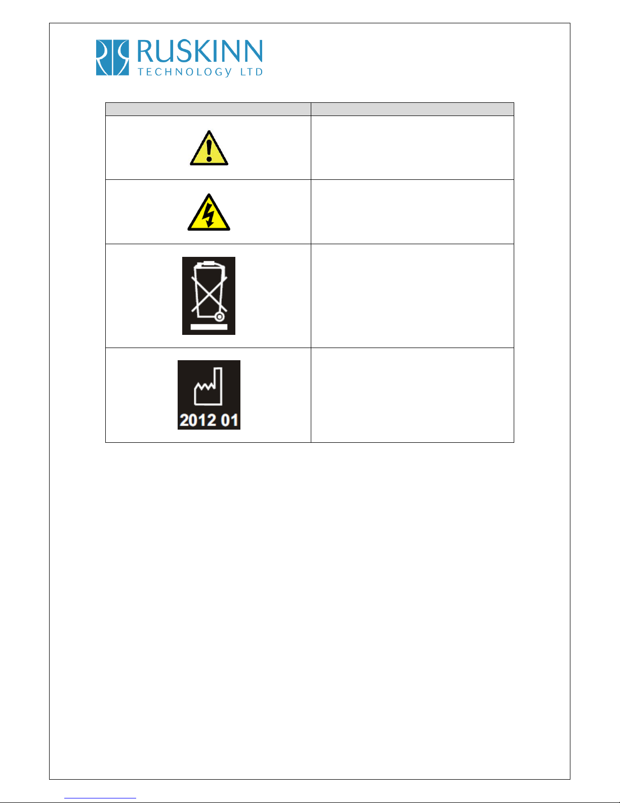
1.1 Safety Instructions
For your safety, the safety of others using the workstation and those around you;
The covers on both ends and the top of the workstation must not be removed by anyone
other than a qualified service engineer. There are no end user serviceable parts within
these covers.
The workstation must be connected to a protective earth.
Only the power cord supplied with the workstation should be used to connect the
workstation to the mains supply.
Gas regulators must be used for each gas supply. A 2 stage regulator should be used for a
bottled gas supply. The maximum supply pressure permissible is 4 bar gauge.
The maximum permissible concentration of Hydrogen in the anoxic mixed gas is 10%
Hydrogen.
Only the gasses specified in this manual may be used.
The maximum power rating of the internal socket must not be exceeded, if fitted.
The humidifier screw cap must not be covered or blocked.
The humidifier/ pressure relief tank must not be overfilled.
The spot light should not be used continuously for more than 10 minutes. The spot light
should be allowed to cool for at least 10 minutes between uses.
The cooling fan covers and cooling vents must not be covered or blocked.
The workstation should not be lifted by the glove ports, the interlock or the Single Plate
Entry System (if fitted).
The weight limit for the rear shelf is 12.5kg. The weight must be evenly distributed.
The weight limit for the interlock floor tray is 4kg.
The connection hose for the jar attachment option must not be connected or
disconnected whilst the jar attachment option is switched on.
FAILURE TO ADHERE TO THESE SAFETY INSTRUCTIONS COULD CAUSE SERIOUS INJURY AND WILL
INVALIDATE THE WORKSTATION WARRANTY. RUSKINN TECHNOLOGY LIMITED ACCEPTS NO
RESPONSIBILITY FOR ANY ACCIDENT, INJURY OR LOSS CAUSED BY UNSAFE OPERATION OF THE
WORKSTATION

Concept 400
UM-018 Version 1.4 7 Concept 400 end user manual
1.2 Regulatory compliance
This product complies with the essential EEA requirements for Electrical Safety and the Low Voltage
Directive 2006/95/EC as well as Electromagnetic compatibility as set out in the EMC Directive
204/108/EC.
1.3 Symbols
Before using the Concept 400, please ensure that you are familiar with the symbols on the Concept
400. Fig.1 explains the symbols found on the Concept 400;
Fig.1 Concept 400 symbols
Symbol
Meaning
Refer to user manual.
R
Alternating current
O
Off
I
On
Primary earth stud
This product complies with the essential EEA
requirements for Electrical Safety and
Electromagnetic compatibility as set out in
the EMC directive 204/108/EC and the Low
Voltage Directive 2006/95/EC

Concept 400
UM-018 Version 1.4 8 Concept 400 end user manual
Symbol
Meaning
Caution, do not remove covers. No end user
serviceable parts behind covers.
Warning, this equipment contains high
voltage circuitry
Concept 400 contains hazardous
components and must not be disposed of at
a household waste site. Instead it should be
taken to the appropriate collection point for
the recycling of electrical and electronic
equipment.
Date of manufacture in format
YYYY MM
1.4 Installation and relocation
Concept 400 should only be installed or relocated by a qualified engineer. To arrange installation or
relocation, please contact your local distributor.

Concept 400
UM-018 Version 1.4 9 Concept 400 end user manual
1.5 Weight and dimensions
The Concept 400 workstation weighs approximately 80kg. Fig.2 lists the dimensions of the Concept
400 workstation;
Fig.2 Concept 400 workstation dimensions
External width
1120 mm
External height
750 mm
External depth
720 mm
Workstation chamber internal width
800 mm
Workstation chamber internal height
480 mm
Workstation chamber internal depth
500 mm
Interlock internal width
120 mm
Interlock internal height
260 mm
Interlock internal depth
280 mm
Interlock outer door clear opening width
125 mm
Interlock outer door clear opening height
235 mm
Interlock inner door clear opening width
235 mm
Interlock inner door clear opening height
235 mm

Concept 400
UM-018 Version 1.4 10 Concept 400 end user manual
2. Gas and electrical supply requirement
2.1 Gas supply requirements
The Concept 400 workstation requires 2 gas supplies;
Anoxic mixed gas (up to 10% hydrogen, up to 10% carbon dioxide, remainder nitrogen)
Oxygen free nitrogen.
The maximum permissible concentration of hydrogen in the anoxic mixed gas is 10%. The use of
any other gas(ses) will invalidate the warranty and may cause serious injury.
2.2 Gas regulator requirements
Gas regulators must be used with all gas supplies to the workstation. A 2 stage regulator must be
used for each bottled gas supply. Regulators should be available from your local gas supplier.
Ruskinn Technology Limited does not supply gas regulators.
The gas regulator should provide a minimum supply pressure of 3 bar gauge. The maximum supply
pressure permissible is 4 bar gauge. A supply pressure greater than this will damage internal
components of the workstation and will invalidate the warranty.
2.3 Electrical supply requirements
The workstation must be connected to a mains power supply. A power cord is supplied to connect
the workstation to the mains supply. Only the power cord supplied should be used to connect the
workstation to the mains supply. It is advised that the workstation be located no greater than 1
metre from the plug socket. The plug socket should not be obstructed by the Concept 400
workstation. The workstation must be connected to a protective earth.
2.4 Voltage and frequency requirements
To ensure safe operation of the workstation, it must be connected to a supply of the correct voltage
and frequency. The mains supply voltage fluctuations must not exceed +/- 10% of the nominal mains
voltage. The input voltage and frequency requirement for Concept 400 is 100 –240V A.C, 50 –60Hz.
2.5 Power consumption
Fig.3 shows the power consumption ratings;
Fig.3 Power consumption ratings
Supply voltage and frequency
Power consumption
240V A.C, 50Hz
200W
110V A.C, 60Hz
250W

Concept 400
UM-018 Version 1.4 11 Concept 400 end user manual
Note that the power consumption is for normal operating conditions with no equipment connected
to the internal power supply. Power consumption will vary dependent upon the conditions inside
the workstation chamber and the conditions inside the room the workstation is located in.
2.6 Powering the workstation
To switch the workstation on, press the power switch (item 5 in fig.17, section 3.3.7, page 25 or item
7 in fig.18, section 3.3.8, page 25). Note that after switching the workstation on, the commissioning
cycle MUST be run before using the workstation. To switch the workstation off, press the power
switch (item 5 in fig.17, section 3.3.7, page 25 or item 7 in fig.18, section 3.3.8, page 25). Note that a
glove port should be left open when the workstation is switched off, as the pressure inside the
workstation will decrease as the workstation cools. The open glove port will allow the pressure
inside the workstation chamber to equalise with the external pressure.

Concept 400
UM-018 Version 1.4 12 Concept 400 end user manual
3. Workstation overview
3.1 Workstation layout
The Concept 400 workstation consists of 2 main areas; the workstation chamber and the interlock
chamber. The workstation chamber is the main working area of the workstation. Access to the
workstation chamber is provided by the glove ports, the Single Plate Entry System (SPES) and the
interlock. The interlock consists of the interlock chamber, with an inner and outer door and a sliding
floor tray. The Concept 400 workstation is controlled via the control panel.
3.2 Component layout
Please familiarise yourself with the layout of your Concept 400 workstation.
3.2.1 Front view –standard front
Fig.4 shows the front view of the Concept 400 workstation with the standard front screen;
Fig.4 Concept 400 workstation front view with standard front screen
1. Interlock inner door control panel.
2. Glove ports (shown without Ezee Sleeves TM).
3. Single Plate Entry System (SPES).
4. Control panel.
5. Outer door knob.
6. Interlock outer door.
7. Port entry selector knob.
Note that the socket shown in fig.4 is an optional extra. The Concept 400 workstation is equipped
with a rear shelf, not shown in fig.4.

Concept 400
UM-018 Version 1.4 13 Concept 400 end user manual
3.2.2 Front view –removable front
Fig.5 shows the front view of the Concept 400 workstation with the removable front screen;
Fig.5 Concept 400 workstation front view with removable screen
1. Glove ports (shown without Ezee Sleeves TM).
2. Port entry selector knob.
3. Interlock inner door control panel.
4. Control panel.
5. Interlock outer door.
6. Outer door knob.

Concept 400
UM-018 Version 1.4 14 Concept 400 end user manual
3.2.3 Rear view
Fig.6 shows the rear view of the Concept 400 workstation;
Fig.6 Concept 400 workstation rear view
1. Cooling vent outlets.

Concept 400
UM-018 Version 1.4 15 Concept 400 end user manual
3.2.4 Left side view –Standard humidifier
Fig.7 shows the left side view of the Concept 400 workstation with the standard humidifier;
Fig.7 Concept 400 workstation left side view with standard humidifier
1. Condenser fan.
2. Pressure relief tank cover (pressure relief tank bung).
3. Pressure relief tank.
4. Pressure relief tank label.
5. Single Plate Entry System (SPES).
6. Pressure relief tank overflow pipe.

Concept 400
UM-018 Version 1.4 16 Concept 400 end user manual
3.2.5 Left side view –Ultrasonic humidifier
Fig.8 shows the left side view of the Concept 400 workstation with the ultrasonic humidifier;
Fig.8 Concept 400 workstation left side view with ultrasonic humidifier
1. Humidifier tank.
2. Humidifier tank screw cap.
3. Humidifier tank label.
4. Vacuum port (optional extra).
5. Cable gland (optional extra).
6. Condenser fan.
7. Single Plate Entry System (SPES).
Note that the humidifier tank screw cap also provides pressure relief for the workstation chamber.
For this reason, do not cover the humidifier tank screw cap.

Concept 400
UM-018 Version 1.4 17 Concept 400 end user manual
3.2.6 Right side view
Fig.9 shows the right side view of the Concept 400 workstation;
Fig.9 Concept 400 workstation right side view
1. Interlock outer door.
2. Interlock outer door knob.
3. Commissioning cycle cover.
4. Power entry panel
5. Serial number label.
6. Portable appliance test (PAT test) label.

Concept 400
UM-018 Version 1.4 18 Concept 400 end user manual
3.2.7 Right side view –Jar attachment option
Fig.10 shows the right side view of the Concept 400 workstation, fitted with the jar attachment
option optional extra;
Fig.10 Concept 400 workstation right side view with jar attachment option
1. Interlock outer door knob.
2. Jar attachment option control panel.
3. Commissioning cycle cover.
4. Serial number label.
5. Portable appliance test (PAT test) label.
6. Power entry panel.

Concept 400
UM-018 Version 1.4 19 Concept 400 end user manual
3.3 Control system layout
The control system layout varies by model. Please familiarise yourself with the control system layout
of your Concept 400 workstation.
3.3.1 Control panel –Standard humidity control
Fig.11 shows the control panel of Concept 400 workstations equipped with standard humidity
control;
Fig.11 Concept 400 workstation control panel
1. Power indicator. Illuminates to indicate the workstation is connected to the mains power
supply and is switched on.
2. Humidistat. Controls the level of humidity inside the workstation chamber.
3. Condenser fan on. Illuminates to indicate the condenser fan is running.
4. N2low. Illuminates to indicate low pressure in the nitrogen supply to the workstation,
indicating that the nitrogen cylinder needs replacing.
5. ANO2low. Illuminates to indicate low pressure in the anoxic mixed gas supply to the
workstation, indicating that the anoxic mixed gas cylinder needs replacing.
6. Gas demand. Illuminates to indicate a low pressure condition in the workstation chamber.
7. Gas change. Illuminates to indicate that the auto gas change system has activated.

Concept 400
UM-018 Version 1.4 20 Concept 400 end user manual
8. Interlock purge cycle selector.
9. Outer door. Illuminates to indicate that the outer door is open.
10. Inner door. Illuminates to indicate that the inner door is open.
11. Interlock cycle status anaerobic. Illuminates to indicate that the interlock chamber is in an
anaerobic condition.
12. Interlock cycle status purge. Illuminates to indicate that the interlock purge cycle is in
progress.
13. Interlock cycle status aerobic. Illuminates to indicate that the interlock chamber is in an
aerobic condition and requires purging.
14. Start. Press to start the interlock purge cycle.
15. Gas excess. Illuminates to indicate that the gas excess system has activated.
16. Gas alarm. Press to switch the gas alarm on / off.
17. Internal socket (optional extra). Press to switch the internal socket on / off. Note that the
switch will illuminate when the internal socket is on.
18. Chamber light switch. Press to switch the chamber light on / off. Note that the switch will
illuminate when the chamber light is on.
19. Com cycle active. Illuminates to indicate that the commissioning cycle is active.
20. Temperature controller. See section 3.3.3, page 23 for more details.
Note that the internal socket switch (item 17) is fitted to all Concept workstations. If an internal
socket is not fitted, the switch is provided to blank the hole in the control panel and is not
functional. The interlock purge cycle selector (item 8) is not functional. The control panel is shared
with the Invivo2400 workstation, on which the interlock purge cycle is functional. The switch is
provided to blank the hole in the control panel.
Table of contents