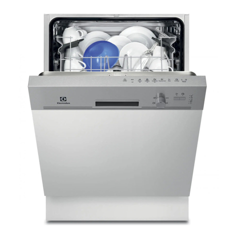
Russell Hobbs RHDW1 User manual

DISHWASHER
SERVICE MANUAL

INDEX page
Tecnical features and security systems
Electrical components
Energy Label
Name Plate
Service mode
Failure Codes
Adjusting the water hardness
Disassembly
Repair Techniques
1
2
8
9
10
11
15
18
53

Tecnical Features
Security Systems
•Flowmeter:
The amount of water intake is in precise control.
•Heater safety protection:
In case of lack of water, with the help of a pressure switch, the resistance is prevented from
being in operation. So both the resistance and the machine itself are protected.
•Overflow and Leakage Protection:
The dishwasher enters overflow mode when there is too much water in the dishwasher, the
excess water gets drained. (a floater rises upwards and senses when overflow water gets
there)
It also detects leaks in the base of the dishwasher, shuts down operation and automatically
pumps out water before contact with floor.
Resettable overflow
1

Electrical Components
Button ( On / Off Switch )
Buton is assembled in the control panel unit.
On / Off ( two pole )
Voltage 250 V
Currency 16 ( 4 ) A
Door Lock
It is a mechanical lock/release system that is closing the
door, supplying the connection of electrical parts in the
machine and cutting off the connection.
Currency 16 (4) A
Circulation Pump
Voltage 220/240 V
Frequency 50 Hz
Total Power 88 W
Coil İsolation Class F
Main(First) Coil Ω95%± 7 Ω
Sub(second) Coil Ω126%± 7 Ω
Thermal Protector 109 °C
Pump Outlet Pressure 300 mbar
Pump Flowrate 60 lt/min
Single direction, single phase, asynchronous and two
pole.
It turns opposite clock direction.
It is assembled to the basement with rubber hangers.
2

Capacitor
Heater Casing Group
•Heater
Voltage 220/240 V
Total Power 2000 W
Resistance 23.19 Ω± ٪5
It is used to heat the washing water.
Heater is not active during the drying process.
It is assembled to the sump and located to the Supply side
of circulation pump.
2,5 µF – 450 V class P2
Capacitor is permanently connected to the
circulation pump coils.
Drain Pump
Voltage
220/240 Volt
Frequency 50 Hz
Total Power
30 W
Flowrate 17 – 21 lt/min
Coil Resistance
143 Ω%± 7
Coil İsolation Class
F
Thermal Protection
120 °C
3

NTC with Thermal Protector
Thermal Protection 83±3 °C
Temperatures
NTC is assembled on the heater Casing Group.
•Pressure Switch
Voltage 220/240 V
Frequency 50 Hz
16 A – 3 Pins
•Diverter
There is diverter at C31 and C41 models
It is assembled to the heater Casing Group.
2 Washing Position
1.Position Upper spray arm
complete
2.Position Lower spray arm
complete
25°- 5000Ω%±5.0
35°- 3300Ω%±5.5
55°- 1520Ω%±6.5
63°- 1174Ω%±7.5
80°- 670Ω%±8.0
90°- 488Ω%±8.5
Voltage 220/240 V
Frequency 50 Hz
Power
Resistance
8 W
6840±٪5 Ω
4

Water Inlet Valve
Single inlet and single outlet standard single
coil selenoid valve.
It is assembled to the basement and connect to the
airbreak by hose.
Regeneration Valve
Voltage 220/240 V
Frequency 50/60 Hz
Total Power 6 W
Resistance 4130±٪10 Ω( 25 Cº )
Regeneration valve is assembled on the water softener.
Parasite Filter
Voltage 220/240 V
Frequency 50/60 Hz
0,1 uF (X1) + 2x0,027uF(Y2) + 1M Ω
It is used to prevent parasites from the main supply. It has
been assemblied to basement.
Turbo Fan Motor
There is a thermal protector.Shaded pole motor , two pole
temperature is between -40–150 Cº .
Voltage
220/240 Volt
Frequency 50-60 Hz
Total Power
6 W
Flowrate 2.5 lt/min
Coil İsolation Class
F
Resistance
3750±٪10 Ω( 20 Cº )
5
There is Turbo Fan Motor only at C4 models.

Salt Sensor
Voltage 250 V
Currency 50 mA
It is assembled to the water softener.
It warns if the salt is less than requested quantity.
Power Cord
Drain Hose
Drain hose maximum height 110cm
Drain hose minimum height 50cm
Drain hose maximum length 400cm
Total Power
15 W
Voltage 220/240 V
Frequency
Resistance
50 Hz.
238.6± ٪ 5 Ω
Coil isolation class:
H
Type
Euro 3’lü 1 mm
2
, copper conducting
İsolation
TS 9760 H05VV-F
Plug TS-IEC 60884–1 PVC injected
Length 1800 mm
6

Detergent / Rinse Aid Dispanser
Detergant dispenser consists of rinse aid and detergant compartment. It has been assemblied to the
inner door by the snap fits. Only one bobbin has been used for operating the system.
Detergant compartment
Main wash compartment (3) 40 cm³
Prewash compartment (2) 5 cm³
Rinse aid compartment (1) :
Dosage Quantities:
Rinse aid compartmnet: 150 cm³
Factory outlet setting position: level 3
Water Softener
Resin Quantity 0,6lt
Capacity of salt compartment 2kg
Total hardness adjustment level 6
Level
Rinse aid dosage
amount
Level 1 1 cc ± 0,5 cc
Level 2 2 cc ± 0,5 cc
Level 3 3 cc ± 20%
Level 4 4 cc ± 20%
Level 5 5 cc ± 20%
Level 6 6 cc ± 20%
Water Hardness
Level
German Hardness
°dH
French hardness
°dF
Bristish hardness
°dE
Water Liter
Level 1 0-5 0-9 0-6 -
Level 2 6-11 10-20 7-14 160lt
Level 3 12-17 21-30 15-21 89lt
Level 4 18-22 31-40 22-28 59lt
Level 5 23-31 41-55 29-39 46lt
Level 6 32-50 56-90 40-63 16lt
1
2
3
7

Energy Label
ENERGY LABEL
LOGO :XXXXXX
MODEL:XXXXXX
ENEGY PERFORMANCE
A
ENERGY CONSUMPTION
A ---- 1,05 kWh / cycle
B ---- 1,20 kWh / cycle
WASHING PERFORMANCE
A,B
DRYING PERFORMANCE
A,B
CAPACITY
Standard place settings 12
persons
WATER CONSUMPTION
13 – 15 lt
8

Name Plate
9

Service Mode :
Starting the service test
Picture 1
Picture 2
After finalizing the above processes; the service program starts automaticly.
Program algrorithm steps follow each other automatically. In case of a problem; the program stops on
the problem step and show failure code. You can understand the problem by looking the failure code.
STEP PROCESS TIME CONTROL
0 Show the last failure
occured before ~6 sec At the beginning of service program
1 Drain ~4 sec Drain pump is running
2 Fill (~3,5lt) ~1min 25
sec
Water inlet valve and flowmeter is controlled.
(At 2,5lt circulation pump starts to run)
3 wash ~1min 10
sec
Circulation pump – detergant dispenser
4 Wash + Heating ~5 min Heater Casing (pressure switch)- NTC- diverter positions
5 Regeneration ~1 min Regeneration value
6 Drain ~20 sec Drain Pump
7 End led highlight
4- Move the programme
selector knob to the reset
position Keep the start/pause
button pressed until program
monitor lights are on and off.
1-Move the programme
selector knob to the first
program and press the
start/pause button while
your machine is not in
operation
2-Keep the start/pause button
pressed down meanwhile
energise the machine by
pressing the On/Off button
3-Keep start/pause button
pressed until flow indicators
are on and off
Start/pause
button
button
Flow
Indicator
10

Failure Codes : C1 Models
ERROR CODE
Wash End Start
/Pause
ERROR
DESCRIPTION
POSSİBLE PROBLEMS
Inadequate
water supply
•Make sure the water input tap is totally open and that there
is no water cut.
•Close the water input tap, separate the water input hose
from the tap and clean the filter at the connection end of
the hose.
•.Water inlet valve filter can be
•Water inlet valve can be out of order
•There can be a problem with the cable connection of water
inlet valve.
•Floater switch can be out of order or have a problem with
the cable connection.
•Pressure switch of the heater casing group can have a
mechanical or cable connection problem.
•
•Circulation pump can be out of order or have a problem
with the cable connection.
•Electronic card can be out of order.
Error of
continuous water
input
•Water inlet valve can be out of order or can not be
closed.
•Electronic card can be out of order.
The waste water
in the machine
cannot be
discharged.
•Water outlet hose is clogged.
•Water discharge hose can be out of order.
•There can be a problem with cable connection of the drain
pump.
•Pressure switch of the heater casing group can have a
mechanical or cable connection problem.
•Electronic card can be out of order.
Intended water
temperature
could not be
reached/ faulty
heater and/or
heater sensor
•NTC can be out of order.
•Faulty NTC cable connection can be faulty. NTCshort or
open circuit.
•Thermal protection can be out of order.
•Heater can be out of order or cable connection can be out
order.
Alarm is active
against water
overflow
•There can be a water leakage from the tub.
•Floater switch can be out of order or have a problem with
the cable connection.
•Electronic card can be out of order.
Electronic card
parameter faulty
•By the Immediate and continuous voltage decreases
software variants can not be kept in the memory of
electronic card.
Faulty
Flowmeter
•Cable connection of flowmeter can be faulty.
•Electronic card can be out of order.
Door is open •Door lock mechanism can be out order.
•There can be o problem with the cable connection of door
lock.
•Electronic card can be out of order.
11

Failure Codes: C2 – C3 – C4 Models
ERROR CODE ERROR
DESCRIPTION CONTROL
DISPLAY WASH RINSE DRY END START/PAUSE
F5
Inadequate water
supply
•Make sure the water input
tap is totally open and that
there is no water cut.
•Close the water input tap,
separate the water input
hose from the tap and clean
the filter at the connection
end of the hose.
•.Water inlet valve filter can
be
•Water inlet valve can be out
of order
•There can be a problem with
the cable connection of water
inlet valve.
•Floater switch can be out of
order or have a problem with
the cable connection.
•Pressure switch of the heater
casing group can have a
mechanical or cable
connection problem.
•Circulation pump can be out
of order or have a problem
with the cable connection.
•Electronic card can be out of
order.
F3
Error of continuous
water input
•Water inlet valve can be out
of order or can not be closed.
•Electronic card can be out of
order.
F2
The waste water in
the machine cannot
be discharged.
•Water outlet hose is clogged.
•Water discharge hose can be
out of order.
•There can be a problem with
cable connection of the drain
pump.
•Pressure switch of the heater
casing group can have a
mechanical or cable
connection problem.
•Electronic card can be out of
order.
12

ERROR CODE ERROR DESCRIPTION CONTROL
DISPLAY WASH RINSE DRY END START/PAUSE
F8
Heater Error: Inadequate
heat
•NTC can be out of order.
•Faulty NTC cable connection
can be faulty. NTCshort or
open circuit.
•Thermal protection can be out
of order.
•Heater can be out of order or
cable connection can be out
order.
Alarm is active against water
overflow
•Floater switch can be out of
order or have a problem with
the cable connection.
•Electronic card can be out of
order.
F1
Alarm is active against water
leakage
•There can be a water leakage
from the tub.
•Floater switch can be out of
order or have a problem with
the cable connection.
•Electronic card can be out of
order.
F7
Exceed heating problem
(water inside the machine is
too high)
•water inside the machine is
>77°C, NTC can be out of
order.
•Electronic card can be out of
order.
•
F9
Diverter position problem
•Diverter electric contacts can
have open circuit
•Cable connection of tghe
diverter can be faulty
•Electronic card can be out of
order.
13

ERROR CODE ERROR
DESCRIPTION CONTROL
DISPLAY WASH RINSE DRY END START/PAUSE
F6
NTC faulty
•NTC can be out of order.
•Faulty NTC cable connection can be
faulty. NTCshort or open circuit.
•Electronic card can be out of order.
FE
Electronic card
parameter faulty
•By the Immediate and continuous voltage
decreases software variants can not be
kept in the memory of electronic card
SE
Electronic card water
hardness faulty
•Water Hardness is not be adjusted or
Water Hardness adjustment can not be
kept in the elctronic card memory.
•Water Hardness shoul be adjusted by
controlling the supply water.
F4
Faulty Flowmeter
•Cable connection of flowmeter can be
faulty.
•Electronic card can be out of order.
FA
Faulty turbidity
sensor
•Kirlilik sensörü kablo bağlantısı hatalı
•Turbidity sensor can be out of order.
•There can be some soil around the
turbidity sensor.
•Electronic card can be out of order.
Door is open
•Door lock mechanism can be out order.
•There can be o problem with the cable
connection of door lock.
•Electronic card can be out of order.
14

ADJUSTING THE WATER HARDNESS
First of all be sure that the machine isn’t in operation
1- Move the programme selector knob to the 0 (Reset) position
while your machine is not in operation.
2- After this operation press the Start/Pause button and keep it
pressed down
3- Meanwhile, energise the machine by pressing the Power On/Off
button
4- Keep the start/pause button pressed until the flow indicators are
on and off. It takes ~5"
- Your machine displays the latest entered water hardness setting.
Water hardness can be adjusted by pressing start/pause button according to Table of Water Hardness
Level Settings.
- After adjusting the water hardness level , press on/off button to save settings in memory.
15

Model : C1
Models C2 – C3
Water
Hardness
Level
German
Hardness
dH
French
Hardness
dF
British
Hardness
dE
Water Hardness Level Indicator
1
0-5
0-9
0-6
Wash light (3h) is open.
2
6-11
10-20
7-14
Rinse light (6h) is open.
3
12-17
21-30
15-21
Dry light (9h) is open.
4
18-22
31-40
22-28
End light (12h) is open.
5
23-31
41-55
29-39
Wash and end light (3h+12h) is open.
6
32-50
56-90
40-63
Rinse and end light (6h+12h) is open.
16

Model C4
Water hardness can be adjusted by pressing “+” and “-“ on display. 3
according to Table of Water Hardness Level Settings.
Water
hardness
level
German
hardness dH
French
hardness dF
British
hardness dE
Hardness Level Indicator
1
0-5
0-9
0-6
L1 is seen on display.
2
6-11
10-20
7-14
L2 is seen on display.
3
12-17
21-30
15-21
L3 is seen on display.
4
18-22
31-40
22-28
L4 is seen on display.
5
23-31
41-55
29-39
L5 is seen on display.
6
32-50
56-90
40-63
L6 is seen on display.
17

DISASSEMBLY
1 ) ACCESSIBILITY
1.1) Top Plate
a) Remove two screws that fix the top plate at the back.
b) Push the top-plate back and pull it up.
18
Other manuals for RHDW1
1
Table of contents
Other Russell Hobbs Dishwasher manuals
Russell Hobbs
Russell Hobbs RHTTDW6 User manual

Russell Hobbs
Russell Hobbs RHDW14SS User manual

Russell Hobbs
Russell Hobbs RHSLDW2 User manual

Russell Hobbs
Russell Hobbs RH60BIDW1-M User manual

Russell Hobbs
Russell Hobbs RHDW3 B User manual

Russell Hobbs
Russell Hobbs RHSLDW4-M (B-M) User manual

Russell Hobbs
Russell Hobbs RH45BISLDW2-M User manual

Russell Hobbs
Russell Hobbs RHSLDW4B User manual
Russell Hobbs
Russell Hobbs RHSLDW1 User manual

Russell Hobbs
Russell Hobbs RHDW1B User manual