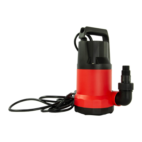
Rx Clear Universal 701460 User manual

2
Section1. IMPORTANT SAFETYINSTRUCTIONS
READ AND FOLLOWALLINSTRUCTIONS
1.1 SafetyInstructions
All electricalworkmustbe performed bya licensed electrician and conformto allnational, state, and
localcodes.When installing and usingthiselectricalequipment, basic safetyprecautionsshould always
be followed, includingthe following:
WARNING
lTo reduce theriskofinjury, do notpermit children to use thisproduct.
lToreduce the riskofpropertydamageorinjury,do notattempttochangethe backwash(multiport,slide,
orfull flow)valve position withthe pump running.
lBooster pumpsare powered bya high voltage electricmotorand mustbe installed bya licensed or
certified electrician ora qualified swimmingpoolservice technician.
lRISKOFELECTRICSHOCK,FIRE, PERSONALINJURY,ORDEATH. Connectonlyto a
branch circuitthatisprotected bya ground-faultcircuit-interrupter(GFCI). Contacta qualified
electrician if you cannotverifythatthe circuit isprotected bya GFCI. Make sure such a GFCIshould be
provided bythe installerand should be tested on a routine basis.Totestthe GFCI,push the testbutton.
TheGFCIshould interruptpower. Push the resetbutton. Powershould be restored. Ifthe GFCIfailsto
operateinthismanner, theGFCIisdefective. Ifthe GFCIinterruptspowerto the pump withoutthe test
button beingpushed, a ground currentisflowing, indicatingthe possibilityofelectricalshock. Do not
use the pump. Disconnectthe pump and have the problemcorrected bya qualifiedservice representative
before using.
Due tothe potentialriskoffire, electricshock, orinjuriestopersons, Booster Pumpsmustbe installed
in accordance with the NationalElectricalCode (NEC ), all localelectricalandsafetycodes, and the
OccupationalSafetyand HealthAct(OSHA ).
lIncorrectlyinstalled equipmentmayfail, causingsevere injuryorpropertydamage.
lDo notconnectthe systemto an unregulated citywatersystemorotherexternalsource ofpressurized
waterproducingpressuresgreaterthan 35 PSI.Trapped airinsystemcan causethe filterlid tobe blown
off, which can result in death, seriouspersonalinjury, orpropertydamage. Be sureall airisoutofthe
systembeforeoperating.
lTo minimize the riskofsevereinjuryordeaththe filterand/orpump should notbesubjected to the
pipingsystempressurization test.
Localcodesmayrequire the poolpipingsystemto be subjectedtoa pressuretest.Theserequirements
are generallynotintendedto applytothepoolequipmentsuch asfilters orpumps. The poolequipment
ispressuretested atthe factory. However, if the WARNING cannotbe followed and pressuretestingof
the pipingsystemmustinclude the filterand/orpump, BE SURETOCOMPLYWITHTHE
FOLLOWING SAFETYINSTRUCTIONS:
uCheckall clamps, bolts, lids, lockringsand systemaccessoriesto ensuretheyareproperlyinstalled
and secured before testing.
uRELEASEALLAIRin the systembeforetesting.
uWaterpressurefortestmustNOTEXCEED 35 PSI.
uWatertemperature fortestmustNOTEXCEED 100°F(38°C).

3
uLimit testto 24 hours.Aftertest, visuallychecksystemto be sureitisreadyforoperation.
lChemical spillsandfumescanweakenpool/spaequipment.Corrosioncancausefiltersand otherequipmenttofail,
resultinginsevereinjuryor propertydamage. Donotstorepoolchemicalsnearyour equipment.
CAUTION
lDo notstart pump dry!Runningthe pump dryforanylength oftime willcausesevere damage and will
void the warranty.
lThispump isforuse withpermanentlyinstalled poolsand mayalso be used withhottubsand spasif so
marked. Do notuse withstorable pools.Apermanentlyinstalled poolisconstructed in oron theground
orina buildingsuch thatit cannotbe readilydisassembled forstorage. Astorablepoolisconstructedso
thatitmaybe readilydisassembled forstorage andreassembled toitsoriginalintegrity.
lDo notinstallwithin an outdoorenclosure orbeneath the skirtofa hottub orportablespa. Thepump
requiresadequate ventilation to maintainairtemperature atlessthan the maximumambienttemperature
ratinglisted on the motorratingplate.
1.2 PoolPumpSuctionEntrapment PreventionGuidelines
WARNING
Pump suction ishazardousand can trap anddrownor disembowelbathers. Do notuse or operate
swimming pools, spa, or hottubsifa suction outletcover ismissing, broken, or loose. The following
guidelinesprovide information forpump installation thatminimizesthe riskofinjuryto users ofpools,spas,
and hottubs:
EntrapmentProtection -Thepump suction systemmustprovide protection againstthe hazardsofsuction
entrapment.
Suction OutletCovers -All suction outletsmusthave correctlyinstalled, screw-fastened covers in place.
All suction outlet(drain)covers mustbe maintained.Draincovers mustbe listed/certified tothe latest
version ofANSI /ASME A112.19.8 oritssuccessorstandard, ANSI/APSP-16. Theymustbe replaced if
cracked, broken, ormissing.
Number ofSuction OutletsPer Pump -Provide atleasttwo (2)hydraulically-balanced main drains, with
covers, assuction outletsforeach circulatingpump suction line. The centers ofthemain drains(suction
outlets) onanyone (1)suction linemustbe atleastthree (3)feetapart,centertocenter. See Figure1.
Thesystem must be built toinclude atleasttwo (2)suction outlets(drains) connected to the pump whenever
the pump isrunning. However, if two (2)main drainsrun into a singlesuction line, the singlesuction line
maybe equipped with a valve thatwillshutoff both main drainsfromthe pump. Thesystemshallbe
constructedsuchthatit shallnotallowforseparate orindependentshutofforisolation ofeach drain. See
Figure 1.
Morethan one (1)pump can be connected to a singlesuction lineaslongasthe requirementsabove are met.
Water Velocity -The maximumwatervelocitythrough the suction fittingorcoverforanysuction outlet
mustbe 1.5 feetpersecondunless the outletcomplieswiththe latestversion ofANSI/ASMEA112.19.8 or
its successorstandard, ANSI/APSP-16, the standardforSuction FittingsForUsein SwimmingPools,
WadingPools, Spas,and HotTubs. In anycase, do notexceed the suction fitting’smaximumdesigned flow
rate.
If100%ofthe pump’sflowcomesfromthe main drainsystem, the maximumwatervelocityinthepump
suction hydraulic systemmustbe six (6)feetpersecond orless, even ifone (1)main drain(suction outlet)is

4
completelyblocked. The flowthrough the remainingmain drain(s)mustcomplywiththe latestversion of
ANSI/ASMEA112.19.8 oritssuccessorstandard, ANSI/APSP-16, the standardforSuction FittingsForUse
in SwimmingPools, Wading Pools, Spas,and HotTubs.
Testing and Certification -Suction outletcoversmusthave been tested bya nationallyrecognized testing
laboratoryand found to complywith the latestversion ofANSI/ASMEA112.19.8 oritssuccessorstandard,
ANSI/APSP-16, the standard forSuction FittingsForUse in SwimmingPools, WadingPools, Spas, and Hot
Tubs.
Fittings -Fittingsrestrictflow;forbestefficiencyusefewestpossiblefittings(butatleasttwo (2)suction
outlets).
Avoid fittingswhich couldcausean air trap.
Poolcleanersuction fittingsmustconformto applicable InternationalAssociation ofPlumbingand
MechanicalOfficials(IAPMO )standards.
Section2. GeneralDescription
2.1 Introduction
Thismanualcontainsinformation forthe properinstallation, operation and maintenance ofthe high-pressure
pump. Proceduresin thismanualmustbe followed exactly. Foraddressinformation, see the backcoverof
thismanual.
2.2 Description
Thehigh-pressure pump supplieshigh pressure waterto the poolcleanerto optimize cleanerefficiency.The
pump isnotself-primingand should onlybe usedwhenthe poolfiltrationpump ison.
NOTICE: Runningthe high-pressure pump withoutafiltration pump will damage the high-pressure pump.
Improperoperation ofthe high-pressure pump willvoid the warranty.
2.3 Preparation
1. Upon receiptofthe pump, checkthe carton fordamage. Open thecartonand checkthe pump for
concealed damage, such ascracks, dentsora bentbase. Ifdamage isfound, contactthe shipperor
distributorwhere you purchased the pump.
2. Inspectthe contentsofthe carton and verifythatall the parts are included. ReplacementPartsList.
Figure1

5
Section3. Installation
3.1 Electrical
1. Thepumpmotormustbesecurelyand adequatelygrounded usingthe green screwprovided. Ground
before attemptingto connectto an electricalpowersupply. Do notgroundto agassupplyline.
2. Insulateallconnectionscarefullyto preventgroundingorshort-circuits. Sharp edgeson terminalsrequire
extra protection. To preventwire nutsfromloosening, tape themusinga suitable, listed (UL, ETL, CSA)
electricalinsulatingtape. Forsafety, and toprevententryofcontaminants, reinstallallconduit and
terminalbox covers. Do notforce connectionsintothe conduit box.
3. Aseparatetime clock(inaddition tothefiltration systemtime clock)isrecommended to controlthe
On/Offfunctionsofthe boosterpump. Amanualswitchcan alsobe used.
4. Ifa time clockisused,setittoturn the pump on atleasta halfan hourafterthe poolfiltration pump is
turned on, and turnthe pump offatleasthalfan hourbefore the filtration pump shutsoff. Periodically
checkthe time clocksettingsto make suretheyareproperlysynchronized.
3.2 Plumbing
NOTICE: Be carefulnottoovertighten anypipe fittingon theinletoroutletofthe boosterpump.
Overtighteningcan causethe housingto crack.
3.2.1 Requirements
Thehigh-pressure Pump requiresa dedicated returnline. Plumb the boosterpump intothesystemso
thatitalwaysreceivesflowfromthe filtration pump.
To ensureproperfunction ofthe pump and the cleaner,referto Figure2and adhereto the following
guidelinesforspecificequipment.
1. Plumb the dedicated lineupstreamofall airinducingequipment.
2. Ifa heaterisinstalled on the system, tap the inletforthe boosterpump intothe return line downstreamand
atleastthree (3)feet(1 meter) fromthe heaterdischarge. See Figure 2. Do nottapthe boosterpumpinlet
intothe three-foot(1 meter)section ofheatsink pipe thatcomesdirectly outofthe heater.
3. Some solarheating systemsutilize the entire water flowwhen the panelsare beingpurged ofair. Ifthe pump
isinstalled in anon-flowpipe duringsolarpanelpurges, install an automatic override to shutoffthe pump.
4. Plumb the boosterpump inlethigher, upstreamand asfarawayaspossiblefroma chlorinator.
3.2.2 Pipe Sizing
1. Use rigid PVCpipe witha minimumdiameterof3/4”, 1-1/2”isrecommended, forthe dedicated return
line. Flexible PVCpipingisnotrecommended forthe dedicated poolreturnline underground asitcan be

6
damaged byexpansion andmovementcaused bythe surge ofpump pressure. Referto Figures3 and 4.
2. Theboosterpump inletconnectionline should be atleast3/4”pipe.
3. Do nottap into the top ofa horizontalline.
4. Use 90°streetellsto minimize bendsand loopsinthe Polarisreinforced hose.
3.2.3 Pump Location
1. the pump withinone 1 foot(30 cm)above the waterlevel.The pump should notbe elevated morethan a
fewfeetabove the waterlevelofthe pool.
2. Ifthe pump islocated belowwaterlevel,isolation valvesmustbe installedon both the suction and return
linesto preventbackflowofpoolwaterduringanyroutine orrequired servicing
3. Thepump and othercirculation equipmentmustbe located morethan 5 feet(1,5 meter) fromthe water.
Choose a location thatwill minimize turnsinthe piping.
4. Thepumpmustbe placed on a solid foundation thatwillnotvibrate. Tofurtherreduce the possibilityof
vibration noise, bolt the pump to the foundation.
5. The pump foundation musthave adequate drainage topreventthe motorfromgettingwet.The pump needs
to be protected fromthe rain and sun.
6. Properventilation isrequiredforthe pump to operate normally.Allmotors generate heatthatmustbe
removed byprovidingproperventilation.
7. Provide access forfutureservice byleavinga cleararea around the pump. Allowplentyofspace above the
pump forservicing.
8. Ifthe equipmentisundercover, provide adequate lighting.
3.2.4 Install the Pump
1.Mountthe pump usingtwo (2)concrete expansion anchorstoensure stability.
2. Slide the quickconnectretainerringoverthe Softube quickconnectthreads. Installquickconnectsonto
pump discharge and supplyportsusingeithersiliconesealantorteflontape. Pipe dope should neverbe
used on quick connectthreads. Do notovertighten.
3. Measure andcutreinforced hose ensuringcutisclean, withno more than a 30ºoffstraightedge. Avoid
unnecessaryloopsorbendsin the hose.
4. Pushthe hose ontothe quickconnectuntil it isflushagainstthehose barb base.
5. Holdingthe hosein place, pulland twistthesleeveon the quickconnectoverthe hose asfaraspossible.
Snap the clipinto place.
3.2.5 InstallationRecommendations
1.Ifthe pump islocated belowwaterlevel,isolation valvesmustbe installed on both sidesofthe pump to
preventbackflowofpoolwaterduringanyroutine orrequired servicing.

7
2. To help preventdifficultyin priming, installthe suction pipe withouthigh points(above inletofpump-
inverted “U”sin plumbing), which can trap air.
3. Thepipingmustbe wellsupportedand notforced togetherwhere constantstresswillbe experienced.
4. Alwaysuse properlysized valves.
5. Use the fewestfittingspossible.Everyadditionalfittinghasthe effectofmovingthe equipmentfarther
awayfromthe water.
3.2.6 ConductPressureTest
WARNING
lWhen pressure testinga systemwith water, air isoften trapped in the systemduring the fillingprocess.
Thisair willcompresswhen the systemispressurized.Shouldthe systemfail, thistrapped aircan
propeldebrisata high speed and causeinjury. Everyefforttoremove trapped air mustbe taken,
includingopeningthe bleedvalve on the filterand looseningthe pump basketlid on the filterpump
whilefillingthe pump.
lTrapped air in systemcan causefilterlidto be blown off, which can resultin death, seriouspersonal
injury, orpropertydamage. Be sure allair isproperlyoutofsystembefore operating. DO NOTUSE
COMPRESSEDAIRTOPRESSURETESTOR CHECKFOR LEAKS.
lWhen pressure testingthesystemwith water,itisveryimportantto make surethatthe pump basketlid
on the filterpump iscompletelysecure.
lDo notpressure testabove35 PSI. Pressuretestingmustbe done bya trained poolprofessional.
Circulation equipmentthatisnottested properlycanfail, which could resultin severeinjuryorproperty
damage.
1. Fillthe systemwith water, usingcaretoeliminatetrapped air.
2. Pressurize the systemwith watertono more than 35 PSI.
3. Close the valve totrappressurized waterinthe system.
4. Observe the systemforleaksand/orpressure decay.
Section4. Operation
4.1 Start-up
CAUTION
²Neverrun the boosterpump withoutwater. Runningthe pump “dry”foranylength oftime can cause
severe damage to both the pump and motorand will void the warranty.
²Neverrun the boosterpump withoutthe cleanerconnected. Runningthe pump withoutthe cleaner
connectedwillcausedamage to the pump impellerand willvoid the warranty.
Ifthisisa newpoolinstallation,make sure allpipingisclearofconstruction debrisand hasbeen properly
pressure tested. The filtershould be checked forproperinstallation, verifyingallconnectionsand clampsare
secure accordingtothemanufacturer'srecommendations.
WARNING
To avoidriskofdamage orinjury, verifythatall poweristurned offbefore starting thisprocedure.

8
1. Turnfiltration pump ON.
2. Open the filterpressurereleaseto relieve the systemsystempressure until watercomesout.
3. Ifthe filterpump islocated belowthe waterlevelofthe pool, openingthe filterpressure release valve will
prime the pump with water.
4. Once all theairhasleftthe filter,closethe pressurerelease valve.
5. Turn on the powertothe boosterpump. Then turn onthe boosterpump.
6. The boosterpump should prime. The time it takesto prime willdepend on theelevation and length ofpipe
used on thesuction supplypipe.
7. Ifthe boosterpump doesnotprime and all theinstructionsto thispointhave been followed, checkfora
suction leak.
Section5. Maintenance
5.1 Winterizing thePump
CAUTION
ØThepump must be protected when freezingtemperaturesare expected. Allowingthe pump to freeze will
causeseveredamage and void the warranty.
ØDo notuseantifreeze solutionsin the pool, spa, orhottub systems! Antifreeze ishighlytoxic and may
damage the circulation system.The onlyexception tothisisPropylene Glycol. Formore information
see yourlocalpool/spa supplystore orcontacta qualified swimmingpoolservicecompany
1. Drain all waterfromthe pump, systemequipment, and piping.
2. Remove the drain plug. Storethe drainplugina safe location and reinstallitwhen the cold weatherseason
isover. Do notlosethe o-ring.
3. Keep the motorcovered and dry.
4. Whenthe systemisreopened foroperation, make sure all piping, valves, wiring, and equipmentarein
accordance withthe manufacturer'srecommendations.Paycloseattention tothefilterand electrical
connections.
5. Thepumpmustbe primed priorto starting;referto Section 4.1, Start-up.

9
Section6. TROUBLESHOOTING
SYMPTOMS possiblecause WHATTO DO
1.The motor does
not start and makes
no noise.
A.Checkthe electricconnections.
B.Checkthat the motor islive.
C.Checkthe protectionfuses.
C. Iftheyareburnt-out, change
them.
N.B. Ifthe fault isrepeated
immediatelythismeansthat the
motorisshort circuiting.
2.The motor does
not start but makes
noise.
A.Ensurethat the mains voltage isthe
sameas the valueon the plate.
B.Ensurethat the connections havebeen
made correctly.
C.Checkthat all thephases arepresent on
the terminalboard.
D.Lookfor possibleblockages inthe pump
or motor.
E.Checkthe condition ofthe capacitor.
B.Correct anyerrors.
C. Ifnot, restorethe missing phase.
D.Removethe blockage.
E.Replace the capacitor.
3.The motor turns
withdifficulty.
A.Checkthe voltagewhichmaybe
insufficient.
B.Checkwhether anymoving partsare
scraping against fixedparts.
B.Eliminatethe cause ofthe
scraping.
4.The pumpdoes
not deliver.
A.The pumphasnot beenprimed
correctly.
B.The diameter ofthe intakepipe is
insufficient.
C.Blocked foot valve.
B.Replace the pipe withone witha
larger diameter.
C. Cleanthe foot valve.
5.The pumpdoes
not prime.
A.The intake pipe orthe footvalveistaking
inair.
B.The downwardslopeof the intakepipe
favoursthe formation ofair pockets.
A.Eliminatethe phenomenon and
primeagain.
B.Correct the inclinationofthe
intakepipe.
6.The pump
supplies insufficient
flow.
A.Blockedfoot valve.
B.The impeller iswornorblocked.
C.The diameter ofthe intakepipe is
insufficient.
A.Clean the foot valve.
B.Removethe obstructions or
replace the wornparts.
C.Replace the pipe withone witha
larger diameter.
7.The pump
vibrates and
operates noisily.
A.Checkthat the pumpand the pipes are
firmlyanchored.
B.Thereiscavitation inthepump, that is
the demandfor water ishigher than it is
abletopump.
C.The pumpisrunning aboveitsplate
characteristics.
A.Fixthe loose partsmore
carefully.
B.Reduce the intake height or
checkfor load losses.
C. It maybe usefultolimit the flow
at delivery.

10
TECHNICALDATA
Model HP RPM Volte/ HZ Amps
701460 1.0HP 3450 115V/230V/60HZ
11.5
Partslisting:
Ref. No. PartNo. Description QTY
1 88601007 Drainplug 2
2 65432002080 Gasket 2
3 647255271 Pump housing 1
4 65221015000 ScrewM8*55 4
5 65244005000 GasketM8 5
6 65431142080 O-ring 1
7 647255204 Base 1
8 65233022000 NutM8 1
9 647255209 Sleeve 1
10 647255208 Undertheimpellerboxcover 3
11 647276071 Impeller 3
12 647255207 Impellerboxsuperstructure 3
13 647255203 Limittablets 1
14 65244023000 Gasket 1
15 65028069000 Seal assembly 1
16 65431143080 O-ring 1
17 647255202 Pump cover 1
18 647255210 Mounting foot 1
19 65231004000 NutM8 4
20 65023153000 1.0HP motor 1
21 647276001 Supporting foot 1
Table of contents
Other Rx Clear Water Pump manuals