SAB Explorer PVR SC User manual


General Information ----------------------------------------------------------------------------------------- 3
Safety and Precaution ------------------------------------------------------------------------------ 3
Accessories -------------------------------------------------------------------------------------------- 5
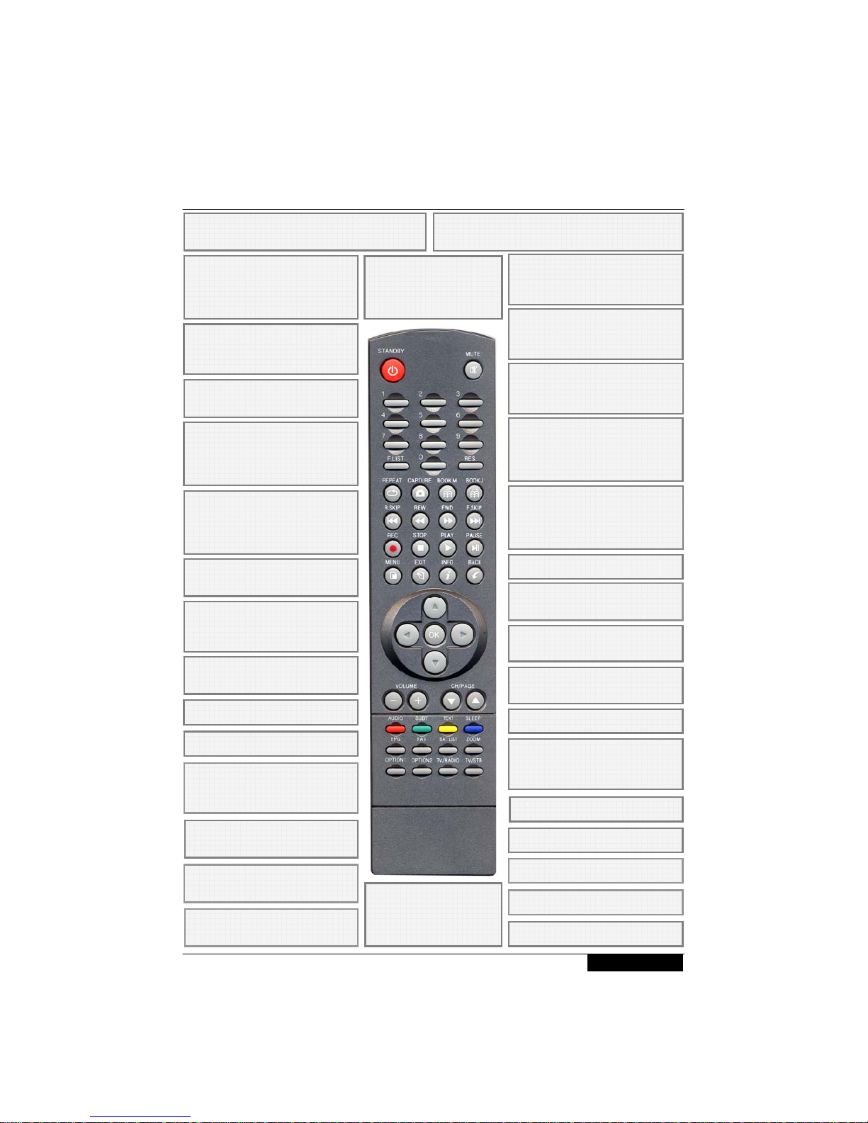
Remote Control Unit ---------------------------------------------------------------------------------------- 6
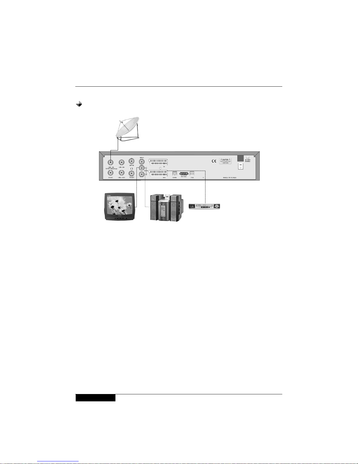
System Connection ------------------------------------------------------------------------------------------ 7
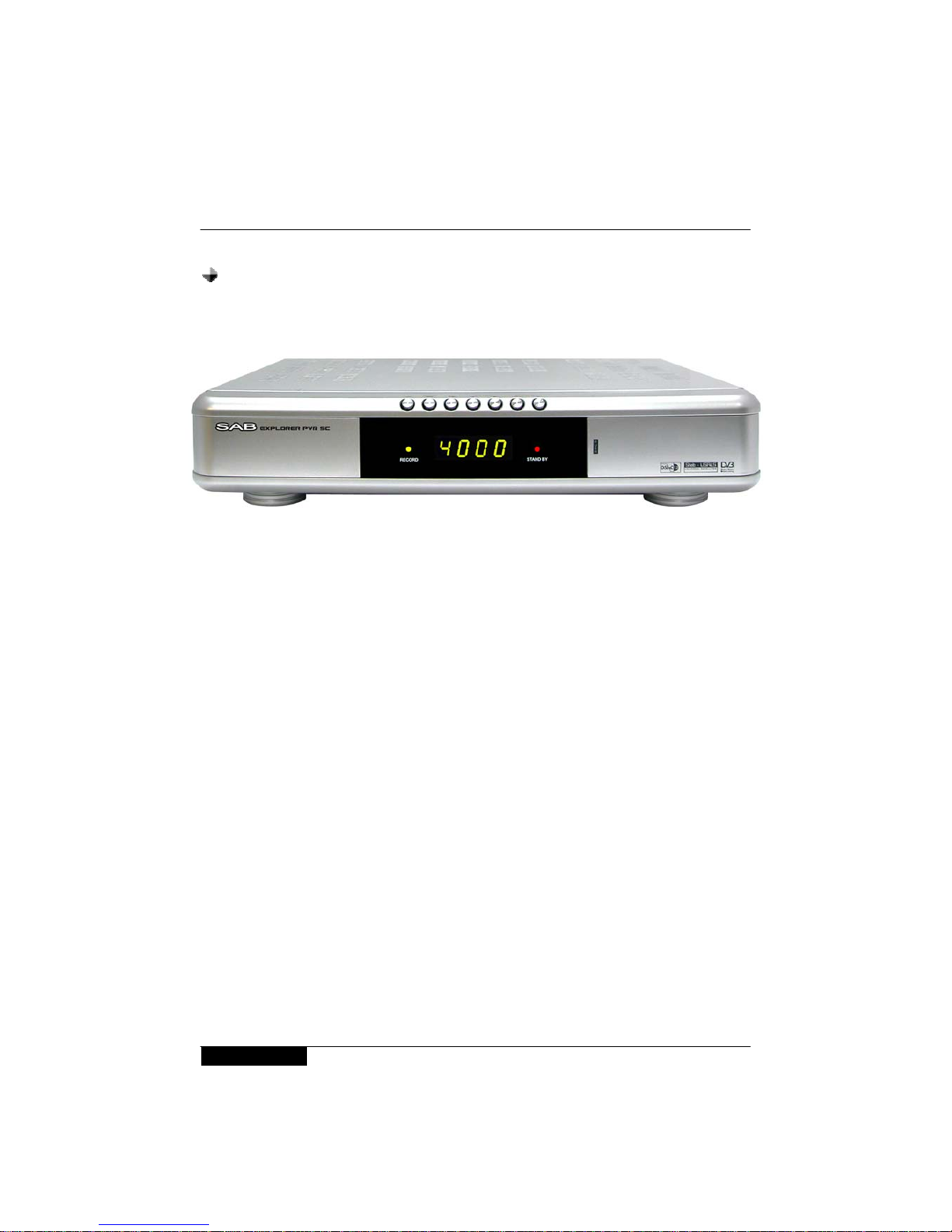
Front Panel -------------------------------------------------------------------------------------------- 7
Rear Panel --------------------------------------------------------------------------------------------- 8
Connecting your System --------------------------------------------------------------------------- 9
Recommanded Antenna Connection ---------------------------------------------------------- 11
Time Setting ----------------------------------------------------------------------------------------- 13
Menu Structure ---------------------------------------------------------------------------------------------- 14
Menu Guide --------------------------------------------------------------------------------------------------- 15
Installation -------------------------------------------------------------------------------------------- 15
Channel Manager ---------------------------------------------------------------------------------- 22
PVR Manager --------------------------------------------------------------------------------------- 24
System Setup --------------------------------------------------------------------------------------- 27
Common Interface ---------------------------------------------------------------------------------- 31
Utility --------------------------------------------------------------------------------------------------- 33
Functions Guide -------------------------------------------------------------------------------------------- 35
Program Guide -------------------------------------------------------------------------------------- 35
Timeshift ---------------------------------------------------------------------------------------------- 36
Bookmark -------------------------------------------------------------------------------------------- 36
Repeat ------------------------------------------------------------------------------------------------ 37
List Menu --------------------------------------------------------------------------------------------- 38
STB Teletext ----------------------------------------------------------------------------------------- 38
Function keys --------------------------------------------------------------------------------------- 39
Change the Attributes of a service ------------------------------------------------------------- 39
Specification ------------------------------------------------------------------------------------------------- 40
Trouble Shooting Guide ---------------------------------------------------------------------------------- 43
Contents
2

◈MAINS SUPPLY
Use only 100 - 250VAC 50/60Hz.
◈OVERLOADING
Do not overload a wall outlet, extension cord or adapter as this may result in fire
electric shock.
◈LIQUIDS
Do not be exposed to dripping or splashing and that no objects filled with
liquids, such as vases, shall be placed on the apparatus.
◈CLEANING
1. Always disconnect the STB power cord from the outlet before cleaning.
2. Use a light damp cloth (no solvents) to dust off the STB.
◈VENTILATION
1. The slots on top of the STB must be left uncovered to allow proper airflow to
the unit.
2. Do not stand the STB on soft furnishings or carpets.
3. Do not expose the STB to direct sunlight or do not place it near a heater.
4. Do not stack electronic equipments on top of the STB.
5. Do not use this appliance in airtight area.
6. Do not open the top cover.
◈CABLE
Use standard certified cables to prevent any malfunction of the STB.
General Information
Safety and Precautions
Thank you for purchasing the digital satellite receiver.
For your safety and proper operation, please take time reading this manual fully before
installing and operating the receiver.
We hope you will be able to take advantage of the numerous functions with the help of
this manual.
3

◈ATTACHMENTS
Do not use any attachments that are not recommended as these may cause
hazard or damage to the STB.
◈CONNECTION TO THE SATELLITE DISH LNB
Disconnect the STB from the mains before connecting or disconnecting the
cables from the satellite dish.
Failure to do so can damage the LNB.
◈CONNECTION TO THE TV
Disconnect the STB from the mains before connecting or disconnecting the
cables from the TV.
Failure to do so can damage the TV.
◈EARTHING
The LNB cable MUST BE EARTHED to the system earth for the satellite dish.
The earthing system must comply with SABS 061.
◈LOCATION
Place the STB indoor in order not to expose to lightening, rain or sunlight.
◈SERVICING
1. Do not attempt to service this product yourself.
2. Refer all servicing to qualified service representatives
NOTICE : The power remains on even when the switch is turned off.
General Information
Safety and Precautions
4

Check the following accessories when you open the box
User’s Manual 1 ea. RCU 1 ea
The device, packaging material and batteries must never be disposed of
with household.
Please obtain appropriate information about regulations in your
community, and dispose of all in accordance with regulations at the
separate locations provided.
Accessories
General Information
5
RF Loopthrough cable 1 ea. Batteries 2 ea.

INFO (INFORMATION)
Display channel status or
various program information of
current service.
TV / RADIO
Receiver switches between TV
and Radio mode.
PG UP/DOWN
Move up/down the cursor
M (MUTE)
Enable or disable audio
NUMERIC KEYS :
Select channels by channel
numbers or enter programming
parameters.
Back (PREVIOUS)
Return to the previous menu,
status or channel
VOL (VOLUME)
Increase or decrease the
volume.
EPG
Display the TV/Radio Electric
Program Guide
VOL (VOLUME)
Increase or decrease the
volume. And move left or right
highlight marked cursor.
CH UP/DOWN
Tune to the next or previous
channel. And move up or down
highlight marked cursor.
MENU
Display the Main Menu EXITCancel the user selection
LIST/OK
Select menu option, or to
updated on entry and to enter
List menu
SLEEP (Blue Key)
Operate sleep mode
AUDIO (Red Key)
Select audio mode (left, right,
stereo, language)
SUBT (Green Key)
Display subtitle contents
TEXT (Yellow Key)
Show Teletext
FAV (Favorite)
Set receiver to favorite
service mode, display
the favorite channel.
Book.J Bookmark jump key
STANDBY (Power)
Power On/Off, Standby
REW Rewind a programme.
PLAY Play a programme.
FWD Fast forwards a
programme.
STOP Stop a programme.
R.SKIP Skip a programme
backward (Default interval : 10
seconds)
REC
Record a programme
PAUSE Pause a programme
F.SKIP Skip a programme
backward (Default interval : 10
seconds)
Book.M Bookmark key
SLEEP Operate Sleep mode.
CAPTURE
Capture current image
REPEAT
Repeat a section
TV/SAT
Receiver switches
between TV and
Satellite receive mode.
Remote Control Unit
Sat list View a satellite list
6

Front Panel
System Connection
7
◈2 LED Display
- Stand by LED : It shows Red LED when the power is off.
- REC by LED : It shows GREEN LED when a program being recorded.
◈Normal Display : It shows 4 digits of Channel number when the power is on. But it
shows current time in Standby mode.
On : “run” is displayed on the LED Display panel and shows the current channel
number.
Standby : You can see the clock works.
◈Tact switch : Standby, CH UP/DOWN , VOL UP/DOWN . MENU , OK
◈Common Interface slot
NOTICE :
1. Current time is based on the TDT(Time and Date Table) at the stream of the
current service. If the TDT information is not correct, current time might be
incorrect.
2. Please do not insert metal or alien substance into the slot for the modules
and Smartcards. In doing so can cause damage to the STB and reduce its life
span.

System Connection
Rear Panel
Please refer to the diagram above for all possible connections of your receiver
Do not connect the unit to the mains socket until all other connections
have been made and checked.
1) LNB1 IN : This port is to connect the coaxial cable from LNB of your Dish.
2) LNB1 OUT : This enables the connection of an Analogue receiver.
3) LNB2 IN : This port is to connect a satellite antenna cable or connect LNB 1 OUT.
4) LNB2 OUT : This enables the connector of an Analogue/Digital receiver.
5) ANT IN : This is used to connect the analogue antenna input.
6) TV OUT : This is used to connect your TV through RF cable.
7) VIDEO : This RCA connector is used to connect your TV through RCA cable.
AUDIO R/L : These RCA connectors are used to connect your TV through RCA
cable or any external audio amp or system.
8) VCR SCART : This Scart connector is used to connect any external video.
9) TV SCART : This is used to connect your TV through Scart cable
10)S/PDIF : This is used to connect with Digital audio amplifier (Optional)
11)RS 232C SERIAL PORT : This is used to connect your receiver with a computer
or other STB through a serial cable.
12)USB : PC to STB, STB to PC data transfer and receiver (Optional)
①②③④⑤⑥ ⑦⑧⑨⑩⑪⑫
8

◈TV Only
System Connection
◈With External Audio / Hi-Fi System
Connecting Your System
• To connect any external Audio Hi-Fi system, the receiver has been provided
with two RCA connectors at the back of the receiver marked with Audio L
and R.
• Connect an RCA stereo cable from the AUDIO L, R jacks on the back of the
STB to the LINE, AUX, SPARE OR EXTRA input jacks on your Hi-Fi System.
9
• Connect one end of RCA cable to the RCA jack on the back of the STB and the
other end to a RCA jack on your TV.
• Connect one end of Scart cable to the Scart jack on the back of the STB and the
other end to a Scart jack on your TV.
• Finally connect the coaxial cable from the LNB to the LNB IN jack on the STB.
There are two ways to connect the STB to your existing TV system. We recommend using
one of the following cases for the best result :
• Connect one end of Scart cable to the Scart jack on the back of the STB and the
other end to a Scart jack on your VCR.
◈TV with VCR

System Connection
Connecting Your System
◈TV with Motorized System (DiSEqC 1.2)
• Connect one end of RCA cable to the RCA jack on the back of the STB and the
other end to a RCA jack on your TV.
• Or connect one end of Scart cable to the Scart jack on the back of the STB and the
other end to a Scart jack on your TV.
• Connect one end of your coaxial cable to the LNB IN connector on the STB and the
other end to the REC or Receiver connector on the DiSEqC 1.2 motor.
• Connect the coaxial cable from the LNB to the LNB connector on the DiSEqC 1.2
motor.
There are two ways to connect the STB to your existing TV system. We
recommend using one of the following cases for the best result
All our receivers are designed to be DiSEqC 1.0 and DiSEqC 1.2 compatible.
This allows multiple antennas to be connected to the STB at the same time.
If you have two or more fixed antennas or LNBs, then we recommend you use a
DiSEqC 1.0 switch.
Connect the coaxial cable from the first LNB to the LNB 1 or LNB A input connector
of the DiSEqC switch.
Do the same for any other LNBs that you have.
Connect one end of a coaxial cable to the RF output connector of the DiSEqC
switch, connect the other end to the LNB IN socket on the STB.
To the digital receiver, you can connect either a single satellite antenna directly or
LNB of multi-feed equipment.
◈Reference
DiSEqC 1.0 Connection
USALS System
When it comes to USALS System, please refer to Page 17.
10

System Connection
Recommended Antenna Connection
11
◈When you set the PVR to Loop Mode.
1. When a user has one antenna.
Input a single source to Tuner A, and input the output signal from Tuner A to Tuner B
using a splitter or loop through.
2. When a user has two antenna.
Connect two antennas to DiSEqC and input the outputs to Tuner A. Then input the
output signal from Tuner A to Tuner B using a splitter or loop through.
Note: A splitter is recommended in the single mode. (For Tuner A, use a splitter with
the function of DC bypass, and for Tuner B use a splitter regardless of the
function of DC bypass.) Otherwise, it is recommended to use a splitter. Use
only a splitter in order to connect another set-top-box using a loop through to
your PVR.

System Connection
Recommended Antenna Connection
12
◈When you set the PVR to Dual Mode.
To provide Live and Timeshift services , and Recording service through Tuner A or
Tuner B, input a signal source of the same attributes with the signal input to Tuner A to
Tuner B.
◈When you set the PVR to Split Mode.
Tuner A & Tuner B are activating seperately in this mode.
Connect two antennas to each tuners.

Setting Up Your System
13
Time Setting enables you to set your local time, manage time on the basis of your
standards.
When you initially power on, enter the Time Setting menu, and you set the local
Time, your STB will provide all services based on the initial set time.
In order to set an initial time, set date/month/year/hour/minute.
After setting the initial time here, you can also change the time in Time Setting of
Main menu. When plugged out and re-plugged in, you need to set your Local time
again.
Time Setting

Main Menu
Main Menu
Common Interface
System Setup
Utility
PVR Manager
Channel Manager
Installation
Service searching
Download Software
Factory Reset
Edit Channels
Edit Favorites
Timer List
Recording
TimeShift
Skip Time
Bookmark Image
Format HDD
Language Settings
System Settings
Modulator
Settings
Time Settings
Parental Control
System Information
Captured Image
Calender
Tetris
USB
Receive DB from PC
Send DB to PC
Receive DB from STB
Menu Language
Audio Language
Subtitle Language
Video Output
Aspect Ratio
Display Type
OSD Transparency
Display Channel Info
System Lock
Channel Manager Lock
Installation Lock
Change Password
RF Channel
RF Type
Time Mode
Time
Send DB to STB
Summer Time
Wake Up Time
Wake Up Status
Radio Screen Saver
Time Zone
Menu Structure
14

3) LNB Power
Depending on the type of LNB cling to your antenna, you can supply either LNB
power by setting “On” or not by setting “Off”.
Place the cursor on the satellite which you want to edit and press the “Red” key to
move satellite edit menu.
◈Service Searching
4) LNB Frequency
You can select the predefined Local Frequency (0….9, One Cable1/2 , 5150,
9750, 10600, 10750MHz or Universal) by pressing the ◀▶ keys or manually
enter a specific frequency in MHz unit by pressing the numeric keys.
You can input the number only when it displays “0…9”.
Installation
15
1) Tuner Select
PVR has two tuner input. You can select either one
2) Ant Connect
You can select antenna connection mode.
Loop / Split / Dual mode support
Menu Guide :
Edit

2) DiSEqC
DiSEqC must be used when using two or more antennas and LNBs.
Select None, DiSEqC 1.0 , DiSEqC1.1 , MOTOR and USALS.
Edit
16
3) Committed
Set the port number of DiSEqC 1.0 switch
4) UnCommitted
Set the port number of DiSEqC 1.1 switch.
5) Save
After Setup complete, Press “RED” key to save
1) 22KHz
In case you are using a Dual LNB or two antennas connected to a 22KHz tone
switch box, make 22KHz tone switch Enable or Disable to select LNB or antenna.
Menu Guide :
Installation
◈Service Searching

* When selecting “USALS” Yellow color key(in DiSEqC menu)
Edit
Input the value of latitude and
longitude in which the dish-installer is
placed.
As the satellite that you want to target
was selected in the last menu, it is
possible to press “OK”keyin“Rotate”.
Then the degree of an angle for rotate
will be calculated automatically and
the DiSEqC Motor will adjust to rotate
the dish to the previously selected
target satellite.
First of all, when you set this procedure, notice the following point, that is, the zero
degree of DiSEqC Motor must be headed for the due North at initial setup state.
17
* When selecting “MOTOR” Yellow color key(in DiSEqC menu)
•DiSEqC 1.2 Motor : You can move the motor to the left or right by pressing the
◀▶ keys continuously, but when you stop pressing the ◀▶ keys, the motor will
be stopped.
•Save : When you press the “OK” key, current position of the DiSEqC motor will
be saved.
•Go to Reference : Move to the position “O”.
•Calculation : The difference between the current position and the new position of
the current satellite is applied to all the other satellite also.
•Limit : You can set the maximum move extent. You can control “Enable”or
“Disable” mode. When you select “Enable”, “East limit” and “West Limit” will be
activated.
Press the “OK” key, then current position will be restored as each limit.
•Reset : After select the “Reset” and press the “OK” key, the original value of
motor will be restored.
Menu Guide :
Installation
◈Service Searching

STB will automatically search all TV/Radio channels from a satellite and save them
into the Channel List.
You can see the progressive status of channel searching. Press the Red or Exit
key to stop Channel Search.
When the Channel Search is completed, the result will be saved and the first
channel of the searched ones will be displayed.
Scan
Notice : Please wait for the receiver to process all the channels, and note
that the “Channel Search” procedure may take a few minutes.
18
Rename
Select the satellite name you would like to rename and press the “OK” key.
By using the “BACK” buttons, Move to be previous menu. Press “BLUE” key to Save.
Select the satellite you want to scan by using the ▲▼ keys .
Press the “OK” key and Scan will begin. 7-Segment will display “SCAΠ”.
1) Network
If you want to have all other
Transponder information, you need to
Select network ‘ On ‘.
2) Search Mode
You can select ALL / FTA option
mode in each satellite by
Using the the ◀▶keys.
Menu Guide :
Installation
◈Service Searching

• Press the red key to change the parameter values of the selected transponder.
• Place the cursor on the sub menu by using the ▲▼ keys and press the ◀▶keys
or “ NUMERIC” key to change the setting.
• Insert the frequency of the transponder you want to edit.
• Select the polarization of the transponder you want to edit ( Horizontal / Vertical ) .
• Input the symbol rate of the transponder you want to edit.
• Select the FEC (Forward Error Correction) of the transponder you want to edit.
1) Edit
19
If you cannot find the desired transponder from the transponder list, you can add
it by inputting appropriate parameter values for a new transponder.
2) Add
Transponder
Menu Guide :
Installation
◈Service Searching

If you cannot find it from the transponder list, you should insert all the setting
parameters.
If you want to have all other transponder information, select network “On”.
You can also search a special channel of the specified transponder by specifying
Video PID (Packet Identifier), Audio PID and PCR PID.
When you want to search a specified channel, please input the specified PCR PID
with specified Video/Audio PID.
3) Scan
20
4) Delete
Press the “Blue” key to delete the selected transponders.
Menu Guide :
Installation
Transponder
◈Service Searching
Table of contents
Other SAB Receiver manuals