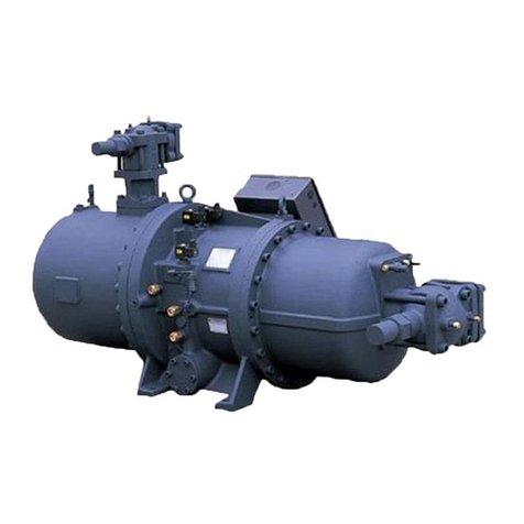
SABROE SAB 193 S Installation and operation manual

SAB 193-233-283 S A-frame (including ATEX)
Screw compressor units
Engineering manual EN


Engineering manual - SAB 193-233-283 S A-frame (including ATEX)
008831 en 2022.02 3/175
Manual for SAB 193/233/283 A-frame screw compressors
Unit no.
Compressor 193 233 283
Compressor type S L E X
Oil separator type OHU 04123/2719 D1 OHU 04136/3231 D2
Refrigerant
R717 HFC/
HCFC
Other: _________
Oil type Oil type: _________________ Evap. temp. _____ Cond. temp. _____
Control UniSAB III None Other
Oil filter Single Dual
Oil cooling
Refrigerant-cooled oil cooler Water-cooled oil cooler
No oil cooler
Liquid injection in compressor Single port Dual port
Discharge port Standard AC (Low Viport)
Oil pump
Economiser system
(ECO-system) Economiser connection Economiser type _________
Ex-execution (ATEX) T3 T4 Other: _________
Supply voltage
Motor 3 x _________V / _________ Hz
Control 1 x _________V / ________ Hz
Heating elements (phasing)1 x _________V / ________ Hz
Motor
IP23 IP55
Power ________ kw Size IEC _________
Anti-condensation heater
Drive type Fixed speed Variable speed (VSD)
UniSAB setting
values Separator velocity ref. _______ Separator velocity ref. CR _______

Engineering manual - SAB 193-233-283 S A-frame (including ATEX)
4/175 008831 en 2022.02
Safety valve:
Data for calculation of
downstream line accord-
ing to EN 13136
Vessel data
Type External surface
[m2]
Design pressure
[bar]
Condenser
Evaporator
Liquid separator
Oil separator
Oil cooler
Economiser
Other
Pressure loss, if any, from safety valve to customer connection
(based on design pressure) [bar] _____________
Safety valve type:
Back-pressure dependent
Back-pressure independent

Engineering manual - SAB 193-233-283 S A-frame (including ATEX)
008831 en 2022.02 5/175
Contents
1. Introduction......................................................................................... 11
1.1 Purpose .................................................................................... 11
1.2 Main users ................................................................................ 11
1.3 Compressor name, Sabroe/Frick................................................. 11
1.4 Amendments to the manual ........................................................ 12
1.5 Manufacturer's information ......................................................... 13
1.6 Safety precaution definitions used in this manual.......................... 14
1.7 Requirements for competent persons .......................................... 14
2. Signs and warnings............................................................................. 15
2.1 Main users ................................................................................15
2.2 Identification of Johnson Controls Denmark equipment ................. 15
2.3 Compressor name plate ............................................................. 16
2.4 Compressor name plate - ATEX .................................................. 17
2.5 Labelling of explosion-proof equipment........................................18
2.6 Vessel name plate...................................................................... 19
2.7 Unit/pipe system name plate.......................................................21
2.8 Signs .......................................................................................23
3. Safety precautions .............................................................................. 24
3.1 Areas of application.................................................................... 24
3.1.1 Application of the screw compressor ....................................24
3.1.2 Application of combustion engines ....................................... 24
3.2 Safety precautions .....................................................................25
3.2.1 General precautions............................................................ 25
3.2.2 Work area safety.................................................................25
3.2.3 During operation .................................................................25
3.2.4 Safety during maintenance and service ................................ 26
3.2.5 Electrical installations.......................................................... 27
3.2.6 Power supply...................................................................... 27
3.2.7 Lubricating oils ................................................................... 28
3.2.8 Refrigerants ....................................................................... 28
3.2.9 Purging a refrigeration plant................................................. 28
3.2.10 F-gas regulation (fluorinated greenhouse gases)................... 29
3.2.11 First aid for accidents with ammonia..................................... 31
3.2.12 First aid for accidents with HFC/HCFC .................................32
3.2.13 Protecting the operator as well as the environment ................ 33

Engineering manual - SAB 193-233-283 S A-frame (including ATEX)
6/175 008831 en 2022.02
4. Technical description .......................................................................... 36
4.1 Description of the screw compressor ...........................................36
4.2 Marine application...................................................................... 38
4.3 Description of main components and systems.............................. 39
4.4 Control system .......................................................................... 39
4.5 Compressor .............................................................................. 40
4.6 Variable speed drive (VSD)......................................................... 42
4.7 Compressor lubrication system ...................................................42
4.8 Oil injection valve ....................................................................... 43
4.9 No pump oil system.................................................................... 43
4.10 Demand pump oil system ........................................................... 43
4.11 Flow security ............................................................................. 43
4.12 Compressor oil separation system...............................................43
4.13 Automatic oil return valve ........................................................... 46
4.14 External oil filter .........................................................................47
4.15 Unit with double oil filter.............................................................. 48
4.16 Compressor hydraulic system ..................................................... 48
4.17 Compressor oil cooling systems.................................................. 50
4.18 Suction check valve by-pass.......................................................51
4.19 Requirements for ambient temperatures and humidity ..................53
4.20 Oil carry-over to plant .................................................................54
4.21 Selecting lubricating oil for Sabroe screw compressors ................. 55
4.22 Oil charge.................................................................................. 55
4.23 Heating rod element for oil heating, pos. 30.................................. 55
4.24 Oil level switch........................................................................... 56
4.25 Cold-start system....................................................................... 56
4.26 Compressor protecting system, pos. 220 and 221 ........................ 58
4.27 Oil cooling system and general piping layout ................................ 59
4.28 Liquid injection oil cooling ........................................................... 59
4.29 Thermosyphon oil cooling........................................................... 61
4.30 Water-cooled oil cooling ............................................................. 63
4.31 Connection to AlfaNova oil cooler................................................ 65
4.32 KRACHT oil pump ...................................................................... 66
4.33 Economiser, high-stage (optional) ...............................................67
4.34 General piping diagram .............................................................. 71
4.35 Key to piping diagram.................................................................74
4.36 Instrumentation.......................................................................... 76

Engineering manual - SAB 193-233-283 S A-frame (including ATEX)
008831 en 2022.02 7/175
5. Physical and connection data ............................................................. 78
5.1 Physical data ............................................................................. 78
5.2 Allowable flange loads................................................................ 79
5.3 Mounting of suction isolation valve .............................................. 80
5.4 Connection data ........................................................................81
5.4.1 Connections to compressor unit ...........................................81
5.4.2 Electrical connections ......................................................... 87
5.4.3 List of components..............................................................88
6. Technical data ..................................................................................... 90
6.1 Data for compressor units........................................................... 90
6.2 Other data ................................................................................. 92
6.3 Planning the machine room ........................................................ 93
6.4 Minimum compressor flow at 3550 rpm........................................94
6.5 Operating limits.......................................................................... 95
6.6 Selecting electric motor .............................................................. 96
6.7 Motor dimension ........................................................................96
6.8 Motor selection and starting torque.............................................. 97
6.9 Motor/compressor torque ........................................................... 98
6.10 Direction of rotation .................................................................... 99
6.11 Emergency stop.........................................................................99
6.12 Other emergency stop requirements............................................99
6.13 Noise data............................................................................... 100
6.14 Noise data for SAB 193-233-283 .............................................. 100
6.15 Vibrations and test pressure levels ............................................ 101
6.15.1 Vibration data for compressors (all compressor
types) .............................................................................. 101
6.15.2 Test pressure levels for standard compressors and
components ..................................................................... 103
6.15.3 Tightness of Sabroe equipment.......................................... 104
7. Installation instructions..................................................................... 105
7.1 Installation............................................................................... 105
7.2 Safety precautions ................................................................... 105
7.3 Installation data ....................................................................... 105
7.4 Installation and first start-up procedure ...................................... 105
7.5 Installation drawings................................................................. 105
7.6 Personnel requirements ........................................................... 106
7.7 Preparing the installation .......................................................... 106
7.8 Tools and accessories .............................................................. 106

Engineering manual - SAB 193-233-283 S A-frame (including ATEX)
8/175 008831 en 2022.02
7.9 Safety equipment..................................................................... 106
7.10 Local regulations...................................................................... 106
7.11 Preparing the mounting site ...................................................... 106
7.12 Space requirements................................................................. 107
7.13 Lifting and loading instructions .................................................. 107
7.14 Unpacking and inspection......................................................... 107
7.15 Disposal of non-reusable materials............................................ 107
7.16 Moving the equipment to the mounting site ................................ 107
7.17 Alignment of compressor and unit ............................................. 108
7.18 Alignment of unit against foundation .......................................... 108
7.19 Alignment of compressor and motor .......................................... 108
7.20 Laying the unit foundation..........................................................111
7.21 Mounting directly on the foundation ............................................111
7.22 Mass damping between unit and building................................... 112
7.23 Damping using vibration dampers ............................................. 112
7.24 VSD equipment ....................................................................... 115
7.25 Calculation of centre of gravity, support reactions and tipping
angle ...................................................................................... 117
7.26 Instruction for mounting of coupling ........................................... 125
7.27 BPU coupling installation procedure .......................................... 126
7.28 Piping connections................................................................... 128
7.29 Connecting electricity supply..................................................... 129
7.30 Pressure testing....................................................................... 131
7.31 Evacuation of the refrigeration plant .......................................... 132
7.32 Oil charging ............................................................................. 132
7.33 Final installation check ............................................................. 133
8. Components...................................................................................... 134
8.1 UniSAB III ............................................................................... 135
9. Settings............................................................................................. 136
9.1 Control system ........................................................................ 136
10. Operating instructions ...................................................................... 137
11. Maintenance instructions .................................................................. 138
11.1 Safety precautions ................................................................... 138
11.2 Maintenance of compressor unit ............................................... 138
11.3 Stopping routine ...................................................................... 139
11.4 Long-term storage ................................................................... 139

Engineering manual - SAB 193-233-283 S A-frame (including ATEX)
008831 en 2022.02 9/175
11.5 Visual inspection...................................................................... 141
11.6 Measures to be taken............................................................... 141
11.7 General rules for use of lubricating oil in refrigeration
compressors............................................................................ 143
11.8 Assessing the oil...................................................................... 143
11.9 Visual assessment ................................................................... 144
11.10 Analytical evaluation ................................................................ 144
11.11 Analysing the oil....................................................................... 144
11.12 Charging compressor with lubricating oil .................................... 145
11.13 Oil charge................................................................................ 148
11.14 Motor ...................................................................................... 149
12. Faultfinding instructions ................................................................... 150
12.1 How to carry out faultfinding...................................................... 150
12.2 Troubleshooting....................................................................... 151
13. Service instructions .......................................................................... 156
14. Transport instructions....................................................................... 157
14.1 Safety precautions ................................................................... 157
14.2 Transport data ......................................................................... 158
14.3 Personnel requirements ........................................................... 158
14.4 Handling of compressor and unit ............................................... 158
14.5 Loading instructions ................................................................. 159
14.6 Preparations before lifting......................................................... 159
14.7 Loading................................................................................... 159
14.8 Transport instructions............................................................... 160
14.9 Transport regulations ............................................................... 160
14.10 Unpacking and inspecting the unit ............................................. 160
14.11 Moving the equipment to the mounting site ................................ 160
14.12 Storage ................................................................................... 160
15. Commissioning instructions ............................................................. 162
15.1 Safety precautions ................................................................... 162
15.2 Preparations for commissioning ................................................ 162
15.3 Preparations on the mounting site ............................................. 163
15.4 Evacuation and charging of refrigerant ...................................... 163
15.5 Start-up................................................................................... 164
15.6 Commissioning set................................................................... 164
15.7 Checklist for commissioning...................................................... 165

Engineering manual - SAB 193-233-283 S A-frame (including ATEX)
10/175 008831 en 2022.02
16. Spare parts list .................................................................................. 167
17. Spare parts drawings ........................................................................ 168
18. Final disposal.................................................................................... 169
18.1 Safety precautions ................................................................... 169
18.2 Waste disposal ........................................................................ 169
19. Appendices ....................................................................................... 170
Index ................................................................................................. 171

Engineering manual - SAB 193-233-283 S A-frame (including ATEX)
008831 en 2022.02 11/175
Introduction
1. Introduction
The Sabroe screw compressor unit may be configured with various types of equipment de-
pending on its function and requirements. Some of the equipment may be described in this
manual even though it is not featured on your particular unit.
1.1 Purpose
This manual provides all the data usually needed in the sales and planning phases.
• Description of all component parts
• Description of all important technical functions to increase understanding of the product
functionality
• Refrigerant safety
• Connecting data
• Installation instructions
1.2 Main users
This manual is primarily intended for sales, service and contracting purposes.
All compressor intervention within the warranty period must be performed by competent per-
sonnel only. If not, the warranty no longer applies.
1.3 Compressor name, Sabroe/Frick
The compressor in a Sabroe SAB 193, 233 and 283 screw compressor unit is manufactured
by Frick. Below is indicated how the Sabroe and Frick compressor names are made up and
how they correspond to each other.
Sabroe name Frick name
SAB 193 S SGC 1913
SAB 193 L SGC 1918
SAB 233 S SGC 2313
SAB 233 L SGC 2317
SAB 233 E SGC 2321
SAB 283 S SGC 2813
SAB 283 L SGC 2817
SAB 283 E SGC 2821
SAB 283 X SGC 2824
Table 1: Compressor overview
R o t o r d i am e t e r
(first two digits)
Com p r e s s o r
SGC 1 9 1 3
R o t o r L/D
S
R o t o r d i am e t e r
Com p r e s s o r
SAB 193
R o t o r length
S h o r t S
Long L
Extended E
Extreme X
Frick name
SABROE name
H/B
Highpressure/Booster

Engineering manual - SAB 193-233-283 S A-frame (including ATEX)
12/175 008831 en 2022.02
Introduction
1.4 Amendments to the manual
2022.02 Version 7
•Table 48: Maintenance intervals has been updated (intervals for changing
coalescers).
• Subsection 6.15.3: Tightness of Sabroe equipment added.
• Subsection 15.7 Checklist for commissioning added. The list can be
filled in electronically.
• Minor updates.
2020.10 Version 6
• New subsection: 4.8 Oil injection valve.
• Subsection 4.32 KRACHT oil pump has been revised.
• Subsection 4.33 Economiser, high-stage (optional) has been revised.
• Subsection 7.24 VSD equipment has been revised.
• Minor updates.
2020.06 Version 5
• New section added: 7.19 Alignment of compressor and motor .
• Minor updates.
2019.08 Version 4
• BPU coupling mounting procedure has been added.
• Description of new KRACHT oil pump.
• Updated unit drawings.
• Updated P&I diagrams.
• New compressor name plates.
• The ‘Storage’ section in the ‘Transport instructions’ chapter has been revised.
• Various minor corrections and changes.
2018.03 Version 3
• Name plates with EurAsian Conformity mark (EAC) have been added.
• ‘Requirements for competent persons’ section has been added.
• ‘F-gas regulation’ section has been updated.
• Noise data: Add 2dBA to the values for 60 Hz compressors (used to be 3).
• The unsigned declaration of conformity has been removed. It can be found in the oper-
ating manuals.
• And more.

Engineering manual - SAB 193-233-283 S A-frame (including ATEX)
008831 en 2022.02 13/175
Introduction
1.5 Manufacturer's information
This manual is produced by:
Johnson Controls Denmark ApS
Christian X's Vej 201
8270 Højbjerg, Denmark
Phone +45 87 36 70 00
CVR No 19 05 61 71
www.sabroe.com
Copyright © Johnson Controls Denmark
This manual must not be copied without the written permission of Johnson Controls Denmark,
and the contents must not be imparted to a third party nor be used for any unauthorised purpo-
ses. Contravention will be prosecuted.

Engineering manual - SAB 193-233-283 S A-frame (including ATEX)
14/175 008831 en 2022.02
Introduction
1.6 Safety precaution definitions used in this manual
Danger!
Indicates an imminently hazardous situation which, if not avoided, will result in death or serious
injury.
Warning!
Indicates a potentially hazardous situation or practice which, if not avoided, will result in death
or serious injury.
Caution!
Indicates a potentially hazardous situation or practice which, if not avoided, will result in dam-
age to equipment and/or minor injury.
Note: Indicates an operating procedure, practice, or portion thereof, which is essential to
highlight.
1.7 Requirements for competent persons
• Personnel working on the unit must be competent in accordance with national safety
rules and regulations relating to flammable refrigerants or according to EN 13313.
• Maintenance work must be performed according to EN 378 or ISO 5149 supported by
evidence of appropriate training.
• Assign only competent personnel instructed in safety and all machine functions to oper-
ate or service the compressor/unit according to EN 13313.
• Operators and maintenance personnel must carefully read, understand and fully com-
ply with all alarms and instructions.

Engineering manual - SAB 193-233-283 S A-frame (including ATEX)
008831 en 2022.02 15/175
Signs and warnings
2. Signs and warnings
This chapter describes:
• how to identify equipment from Johnson Controls Denmark
• all warning signs used on equipment delivered by Johnson Controls Denmark
• how information important to safety of personnel and equipment is presented in instruc-
tions belonging to equipment delivered by Johnson Controls Denmark
2.1 Main users
Information concerning Signs and warnings is intended for all users.
The following describes the importance of the individual signs attached to the Johnson Con-
trols Denmark products.
Before a compressor/unit is put into operation, it must be fitted with the warning signs belong-
ing to the type of compressor/unit in accordance with the rules and regulations in force.
2.2 Identification of Johnson Controls Denmark equipment
All Johnson Controls Denmark equipment can be identified by one or several name plates on
the unit. The name plates are illustrated on the following pages.

Engineering manual - SAB 193-233-283 S A-frame (including ATEX)
16/175 008831 en 2022.02
Signs and warnings
2.3 Compressor name plate
Fig. 1: Compressor name plate Fig. 2: Refrigerant plates
Note: The compressor is fitted with a name plate, Fig. 1, and one of the two refrigerant name
plates shown in Fig. 2.
The rotary screw compressor serial numbers contain the following information:
Example: 10240A90000015Z.
Plant Decade Month Year Global seq. no.
Additional
remarks
1024 0 A 9 0000015 Z
Month
A=JAN, B=FEB, C=MAR, D=APR, E=MAY, F=JUN,
G=JUL, H=AUG, K=SEP, L=OCT, M=NOV, N=DEC.
Additional remarks
R = Remanufactured
Z = Deviation from standard configuration.
The compressor name plate contains this information:
Model no. Manufacturer type designation.
Part no. Manufacturer part number.
Serial no. Compressor manufacturing number.
Max. driver speed - rpm Maximum number of revolutions allowed.
Max. allowable pressure - psig/bar Maximum working pressure of compressor (psig/bar).
Assembled in Manufacturing country.

Engineering manual - SAB 193-233-283 S A-frame (including ATEX)
008831 en 2022.02 17/175
Signs and warnings
2.4 Compressor name plate - ATEX
Fig. 3: Name plate for an ATEX compressor
The ATEX compressor name plate contains this information:
Model no. Manufacturer type designation.
Part no. Manufacturer part number.
Serial no. Compressor manufacturing number.
Max. driver speed - rpm Maximum number of revolutions allowed.
Max. allowable pressure - psig/bar Maximum working pressure of compressor (psig/bar).
Assembled in Manufacturing country.

Engineering manual - SAB 193-233-283 S A-frame (including ATEX)
18/175 008831 en 2022.02
Signs and warnings
2.5 Labelling of explosion-proof equipment
ATEX:
The compressor area of application is indicated next to the Ex-sign on the name plate.
II 2 G T3/T4
II Material group:
II indicates that the equipment is suitable for use in industrial areas above ground.
2
Material category:
2 indicates that the equipment is suitable for use in areas with possible occurrence of
explosive gasses.
G
Hazardous environment:
G indicates that the equipment is suitable for use in potentially explosive gas, vapour
and fog atmospheres.
T3/T4 Temperature class:
indicates the surface temperatures that may occur on the compressor.
Warning!
On ATEX-executions, the limits in Table 2 must always be respected.
Temp. class Max. surface
temp.
Max. temperature of oil to
shaft seal
Min. ignition temperature of
oil
T1 450°C 380°C 500°C
T2 300°C 230°C 350°C
T3 200°C 130°C 250°C
T4 135°C 65°C 185°C
T5 100°C 30°C 150°C
T6 85°C 15°C 135°C
Table 2: Temperature classes - screw compressors

Engineering manual - SAB 193-233-283 S A-frame (including ATEX)
008831 en 2022.02 19/175
Signs and warnings
2.6 Vessel name plate
Fig. 4: Name plate for vessel
Пpoeкт пo cтaндapтy
Design code
Утвepждeн пoд N
°
Approval No
Oбъeм
/Volume
Cpeдa
/Fluid
Тип
/Type
PS
TS
V
M
асса
пустого
cocy
д
a
Empty weight
/
Кат
.
/Cat.
Nº cocy
д
a
Vessel No
год
2516-331
кг
Cтopoнa oбeчaйки
Shell
side
Tube side
Cтopoнa тpyбок
п
l
MПа
MPa
°C
P
a
б
o
ч
ee
двп
e
ни
e
Макс
./
Мин
.
Allowable pressure
Max./Min.
P
aбoчaя тeмпepaтypa
Макс
./
Мин
.
Allowable temperature
Max./Min.
Kg
Year
Johnson Controls Denmark ApS
Christian X's Vej 201
8270 Højbjerg, Denmark
www.sabroe.com
Fig. 5: Name plate for vessel with EurAsian Conformity mark
(EAC)
The pressure vessel name plate is positioned on the shell of the vessel and contains this
information:
Vessel no. Identification no. (serial no.)
Empty weight The empty weight of the vessel in kg.
Year Year of manufacturing.
Type Manufacturer's type designation.
Design code Design code used for the pressure vessel.
Approval no./CAT
The approval no. of the vessel issued by the relevant 3rd party/
notified body.
For EC PED approval: CAT (Category 1, 2, 3 or 4) according to
the PED directive.
Side For heat exchangers only. Refers to the columns ‘Shell side’
and ‘Tube side’.
Fluid
Designation of the primary refrigerant(s) and the secondary re-
frigerant(s).
For EC PED approval: Designation of the refrigerant(s) and/or
the highest fluid group (Group 1 or 2) according to the PED
directive.
Allowable pressure, PS The min. and max. pressures (pressure relative to atmospheric
pressure) that the vessel or vessel part has been designed for.
Allowable temperature, TS The min. and max. temperatures that the vessel or vessel part
has been designed for.
Volume The volume of the vessel or vessel part.
CE xxxx
The CE mark appears on the name plate for EC PED approval.
The four digits make up the registration no. of the notified body/
3rd party in charge.
EAC
The EurAsian Conformity mark (EAC) indicates that the vessel
is in compliance with all relevant technical regulations of the
Eurasian Customs Union.
Johnson Controls D e n m ar k ApS
Christian X 's V e j 201
8 270 Højbj e rg, D e n m ark
www.sabro e .com
This manual suits for next models
2
Table of contents
Popular Compressor manuals by other brands

Ingersoll-Rand
Ingersoll-Rand 9/235 Operating, Maintenance & Parts Manual

Danfoss
Danfoss MPZ Series instructions

EINHELL
EINHELL PRESSITO 40.204.60 Original operating instructions

EINHELL
EINHELL TE-AC 270/24/10 Original operating instructions

BOCK
BOCK FK20/120 N Assembly instructions

KAESER
KAESER ASD T Series Service manual