1 - Introduction
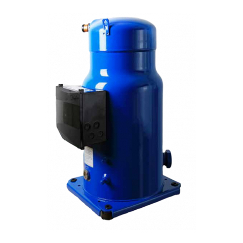
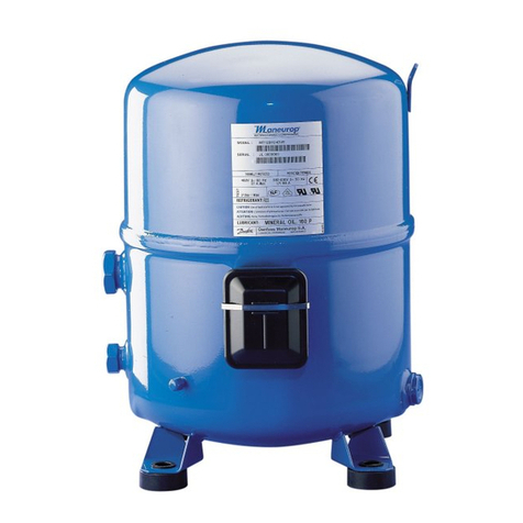
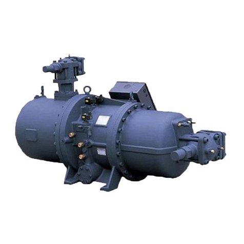
These instructions pertain to the Danfoss
reciprocating compressors MPZ, used for
refrigeration R404A/R507A systems. They are
intended to provide necessary information
regarding safety features and proper handling of
this product.
2 - Transportation, storage
Check the packaging before use.
Beware that all compressor handling must be
carried out with caution. Dedicated packing
handles are to be used for all required manipu-
lation of the compressor; otherwise appropriate
and safe lifting equipment is to be used during
handling and unpacking.
Verify that the compressor is never stored in an
ambient temperature below -35°C (-31°F) or
above 50°C (122°F).
Ensure that the compressor and its packaging are
not exposed to rain or corrosive atmosphere.
3 - Safety measures prior to assembly
Ensure that the ambient temperature, around the
compressor, never exceeds 50°C (122°F) during
o-cycle. Flammable atmosphere are banned.
Makecertainthatthe compressor is mountedonto
a horizontal plane with a maximum slope of 3°.
Verify that the power supply corresponds to
compressor motor characteristics (refer to the
compressor nameplate).
Ensure that refrigerant charging equipment,
vacuum pumps, etc. for HFC refrigerant systems
have been specically reserved for these
refrigerants and never used with other CFC, HCFC
refrigerants.
Useonlycleananddehydratedrefrigeration-grade
copper tubes & silver alloy brazing material.
Verify that all system components are appropriate
(use of refrigerant, etc.), clean and dehydrated be-
fore being connected to the completed assembly.
The piping connected to the compressor must be
congured on the basis of a exible 3-axis design
to dampen vibrations.
4 - Assembly
When removing the plugs, start with the suction
connector plug. Take care to gradually release the
nitrogen holding charge to avoid oil spray.
Connect the compressor to the system as soon as
possible to avoid oil contamination from ambient
moisture.
Ensure that no material enters into the system
while cutting tubing. Moreover, never drill holes
in the pipe work after installation.
Exercise great care while brazing (use only
state-of-the-art practices); vent piping with nitro-
gen gas ow to prevent oxidation. When brazing,
protect the terminal box and painted surfaces
of the compressor from torch heat damage. Be
sure the required safety and control devices are
connected to the circuit.
5 - Leak detection
Never pressurize the circuit with oxygen or dry
air in order to avoid the risk of re or explosion.
Perform a leak detection test on the complete sys-
tem by means of electronic detector after circuit
pressurization with nitrogen & R404A/R507A.
The low side test pressure must not exceed 25 bar
g (362 psig).
Should a leak be discovered, proceed with repair
steps and repeat the leak detection.
Do not use dye for leak detection.
6 - Vacuum dehydration procedure
Connect the vacuum pump to both the LP & HP
sides in order to avoid dead-ending system parts.
Pull down the system under a vacuum of 500
µm Hg (0.67 mbar). Never use the compressor to
vacuum the circuit.
Do not use a megohmmeter or apply power to
the compressor while it is under vacuum, as this
may cause motor burn out.
7 - Electrical connections
Make sure the main power supply to the
system has been switched o and isolated. Refer
to rst page for wiring connection details with
respect to the various motor codes.
Note that MPZ compressors are protected
against excess current and temperature by an
internal overload protector. However the power
line needs to be protected and the compressor
connected to earth.
All electrical components must be selected as per
local standards and compressor requirements.
8 - Filling the system
The compressor shall be switched o: the liquid
refrigerant is charged into the condenser and/or
liquid receiver in liquid phase (compulsory for
refrigerant blends).The charge must be as close
to the nominal system charge as possible in
order to avoid both low pressure operations and
excessive superheating at start-up. If possible,
maintain the refrigerant charge below 2.5 kg.
Above this limit, install a system, such as a
pump-down cycle or suction line accumula-
tor, to protect the compressor against liquid
ood-back.
Never leave the lling cylinder connected to the
circuit to avoid overlling.
9 - Verication before commissioning
Ensure that all service valves, if any, are in the
open position before start-up.
Check that all safety devices are operational
and properly set (safety pressure switch set point,
mechanical relief valve, etc.).Make sure that these
devices comply with both generally and locally
applicable regulations and safety standards.
When using high-pressure switches or relief
valves, the setting must not exceed maximum
service pressure of any system component.
A low-pressure switch is recommended to
prevent operation under vacuum. Use a mini-
mum setting of 0.1 bar (1.5 psig).
Verify that all electrical connections are properly
fastened and in compliance with local safety
regulations.
When a crankcase heater is required (refer to the
Application Guidelines), ensure that it has been
energized for a minimum of 12 hours before
initial start-up and/or after prolonged shutdown
periods.
10 - Start up
Balance the HP/LP pressure before initial start.
As soon as power is energized the compressor
must start, whenever it does not, you have only
few seconds to switch it o in order to avoid
burn-out of the windings ( possible single phase
miswiring).
If the compressor does not start, check voltage
availability on terminals and wiring conformity.
Note: when the overload protector has tripped
out, it may take up several hours to reset.
11 - Check up while compressor is running
Check current draw, voltage and setting of the
suction superheat to reduce risk of slugging.
In all cases, the application range of the compres-
sor must be respected (see overleaf).
Check refrigerant piping or capillary tubes for ab-
normal vibrations (refrigeration line movement in
excess of 1.5 mm necessitates corrective actions,
pipe brackets, etc.).
When needed, additional refrigerant may be added
in liquid phase through the low-pressure side and
as far as possible from the compressor. The com-
pressor must be operating during this process.
Do not overcharge the system. Never release re-
frigerant to atmosphere.
Before leaving installation site, carry out a general
inspection of the installation: cleanliness, noise
and leak detection.
12 - Maintenance
MPZ compressors themselves do not necessi-
tate any special periodic maintenance procedure.
However, check proper operations and mainte-
nance of the system to prevent system-related
compressor problems.
- Verify that safety devices are operational and
properly set.
- Ensure that the circuit is leak tight.
- Check the current draw by the compressor
motor.
- Check that all electrical connections are still
adequately fastened.
- Make sure the compressor is clean and in
good working order; verify the absence of rust
and oxidation on the compressor shell, piping
and electrical connections.
- Insure that periodic in-service inspections re-
quired by local regulations are performed.
Internal pressure and surface temperature in-
volve permanent risk for maintenance operator
and require appropriate skills and tools. Tubing
temperatures may exceed 100°C (212°F) and
could cause severe body burns.
13 - Warranty
The compressor manufacturing date is printed on
the nameplate. Ensure that the model and serial
number information is always transmitted with
any claim led regarding this product.
Be aware that the product warranty may be void
in the following cases:
• External modications to the compressor
(absence of nameplate, drilling, welding, broken
feet, shock marks),
• Compressor opened by the customer or retur-
ned unsealed.
• Presence of rust or water inside the compressor.
• Addition of leak-detection dye in the lubri-
cant, use of a refrigerant or lubricant not appro-
ved by Danfoss.
• Any deviation from recommended instruc-
tions pertaining to installation, application or
maintenance,
• Use in mobile applications (boats, trains,
trucks...) or under explosive atmospheric envi-
ronment (the compressor connecting box is not
explosion-proof).
• No model number or serial number transmit-
ted with warranty claim.
14 - Replacement
Danfoss recommends not to throw away
a used compressor but to dispose of the
compressor and its oil at a specialised
recycling company site.
8510234P03 © Danfoss Commercial Compressors 09/07
2
Instructions
