Saijo Denki SCV-13-A-VTGP1 User manual

AIR CONDITIONER
User’s Manual
Outdoor Unit Indoor unit
Model no.: Model no.:
Cooling only All Round Cassette 4 Way Cassette Wall Mounted
CVIA-80-CPF3 SCV-13N-A-VTGP1 SCV-13-A-VTGP1 SWV-09N-A-VTGP1
CVIA-100-CPF3 SCV-20N-A-VTGP1 SCV-20-A-VTGP1 SWV-13N-A-VTGP1
CVIA-120-CPF3 SCV-25N-A-VTGP1 SCV-25-A-VTGP1 SWV-20N-A-VTGP1
CVIA-140-CPF3 SCV-30N-A-VTGP1 SCV-30-A-VTGP1 SWV-25N-A-VTGP1
CVIA-160-CPF3 SCV-36N-A-VTGP1 SCV-36-A-VTGP1 SWV-30N-A-VTGP1
CVIA-180-CPF3 SCV-50N-A-VTGP1 SCV-50-A-VTGP1
CVIA-200-CPF3 SCV-60-A-VTGP1
CVIA-220-CPF3 Hi-Wall Ceiling Floor Standing
CVIA-240-CPF3 SWV-09-A-VTGP1 SUV-13-A-VTGP1 SFV-30-A-VTGP1
CVIA-260-CPF3 SWV-13-A-VTGP1 SUV-20-A-VTGP1 SFV-36-A-VTGP1
CVIA-280-CPF3 SWV-20-A-VTGP1 SUV-25-A-VTGP1 SFV-50-A-VTGP1
CVIA-300-CPF3 SWV-25-A-VTGP1 SUV-30-A-VTGP1 SFV-60-A-VTGP1
CVIA-320-CPF3 SWV-30-A-VTGP1 SUV-36-A-VTGP1 SFV-80-A-VTGP1
CVIA-340-CPF3 SWV-36-A-VTGP1 SUV-50-A-VTGP1 SFV-120-A-VTGP1
CVIA-360-CPF3 SUV-60-A-VTGP1
CVIA-380-CPF3 Duct Low Static Duct Medium Static Duct High Static
CVIA-400-CPF3 SDV-13L-A-VTGP1 SDV-13M-A-VTGP1 SDV-13H-A-VTGP1
CVIA-420-CPF3 SDV-20L-A-VTGP1 SDV-20M-A-VTGP1 SDV-20H-A-VTGP1
CVIA-440-CPF3 SDV-25L-A-VTGP1 SDV-25M-A-VTGP1 SDV-25H-A-VTGP1
CVIA-460-CPF3 SDV-30L-A-VTGP1 SDV-30M-A-VTGP1 SDV-30H-A-VTGP1
CVIA-480-CPF3 SDV-36L-A-VTGP1 SDV-36M-A-VTGP1 SDV-36H-A-VTGP1
CVIA-500-CPF3 SDV-50L-A-VTGP1 SDV-50M-A-VTGP1 SDV-50H-A-VTGP1
CVIA-520-CPF3 SDV-60L-A-VTGP1 SDV-60M-A-VTGP1 SDV-60H-A-VTGP1
CVIA-540-CPF3 SDV-80H-A-VTGP1
CVIA-560-CPF3 SDV-120H-A-VTGP1

Please read carefully through these instructions that contain important information which complies with the “Machinery”
Directive (Directive 2006/42/EC), and ensure that you understand them.
Generic Denomination: Air Conditioner
Definition of Qualified Installer or Qualified Service Person
The air conditioner must be installed, maintained, repaired and removed by a qualified installer or qualified service person.
When any of these jobs is to be done, ask a qualified installer or qualified service person to do them for you.
A qualified installer or qualified service person is an agent who has the qualifications and knowledge described in the table
below.
ORIGINAL INSTRUCTION
CONTENTS
1 PRECAUTIONSFORSAFETY ........................................... 4
2 PARTNAMES ........................................................ 9
3 FUNCTIONSOFWIRELESSREMOTE .......... ... 13.......................
4 . . . . . . . . . . . . . . . . . . . . . . . . . . . . . . . . . . . . . . . 22FUNCTIONS OF WIRED REMOTE
5 INSTALLATION ...................................................... 34
6 AIR CONDITIONER OPERATIONS AND PERFORMANCE . . . ................. 35
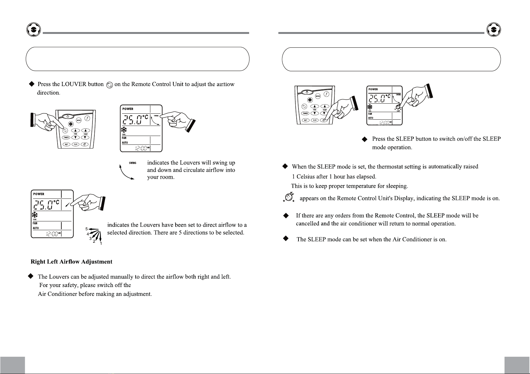
7 LOUVERDIRECTION ................................................. 37
8 AIR CONDITIONER OPERATIONS AND PERFORMANCE . . . ................. 43
9 MAINTENANCE ...................................................... 44
Thank you very much for purchasing SAIJO DENKI Air Conditioner.
Please read this owner’s manual carefully before using your Air Conditioner.
• Be sure to obtain the “Owner’s manual” and “Installation manual” from constructor (or dealer).
Request to constructor or dealer
• Please clearly explain the contents of the Owner’s manual and hand over it.
ADOPTION OF NEW REFRIGERANT
This Air Conditioner adopts a new refrigerant HFC (R410A) instead of the conventional refrigerant R22 in order
to prevent destruction of the ozone layer.
This appliance is not intended for use by person (including children) with reduced physical, sensory or mental
capabilities, or lack of experience and knowledge, unless they have been given supervision or instruction
concerning use of the appliance by a person responsible for their safety.
PAGE
1 2
USER’S MANUAL USER’S MANUAL
Agent Qualifications and knowledge which the agent must have
• Qualified installer • The qualified installer is a person who installs, maintains, relocates and removes the air
conditioners made by Saijo Denki International Co.,Ltd. He or she has been trained to install,
maintain, relocate and remove the air conditioners made by Saijo Denki International Co.,Ltd.
or, alternatively, he or she has been instructed in such operations by an individual or individuals
who have been trained and is thus thoroughly acquainted with the knowledge related to these
operations.
• The qualified installer who is allowed to do the electrical work involved in installation,
relocation and removal has the qualifications pertaining to this electrical work as stipulated by
the local laws and regulations, and he or she is a person who has been trained in matters
relating to electrical work on the air conditioners made by Saijo Denki International Co.,Ltd. or,
alternatively, he or she has been instructed in such matters by an individual or individuals who
have been trained and is thus thoroughly acquainted with the knowledge related to this work.
• The qualified installer who is allowed to do the refrigerant handling and piping work involved in
installation, relocation and removal has the qualifications pertaining to this refrigerant handling
and piping work as stipulated by the local laws and regulations, and he or she is a person who
has been trained in matters relating to refrigerant handling and piping work on the air
conditioners made by Saijo Denki International Co.,Ltd. or, alternatively, he or she has been
instructed in such matters by an individual or individuals who have been trained and is thus
thoroughly acquainted with the knowledge related to this work.
• The qualified installer who is allowed to work at heights has been trained in matters relating to
working at heights with the air conditioners made by Saijo Denki International Co.,Ltd. or,
alternatively, he or she has been instructed in such matters by an individual or individuals who
have been trained and is thus thoroughly acquainted with the knowledge related to this work.
• Qualified service
person
• The qualified service person is a person who installs, repairs, maintains, relocates and
removes the air conditioners made by Saijo Denki International Co.,Ltd. He or she has been
trained to install, repair, maintain, relocate and remove the air conditioners made by Toshiba
Carrier Corporation or, alternatively, he or she has been instructed in such operations by an
individual or individuals who have been trained and is thus thoroughly acquainted with the
knowledge related to these operations.
• The qualified service person who is allowed to do the electrical work involved in installation,
repair, relocation and removal has the qualifications pertaining to this electrical work as
stipulated by the local laws and regulations, and he or she is a person who has been trained in
matters relating to electrical work on the air conditioners made by Saijo Denki International
Co.,Ltd. or, alternatively, he or she has been instructed in such matters by an individual or
individuals who have been trained and is thus thoroughly acquainted with the knowledge related
to this work.
• The qualified service person who is allowed to do the refrigerant handling and piping work
involved in installation, repair, relocation and removal has the qualifications pertaining to this
refrigerant handling and piping work as stipulated by the local laws and regulations, and he or
she is a person who has been trained in matters relating to refrigerant handling and piping work
on the air conditioners made by Saijo Denki International Co.,Ltd. or, alternatively, he or she
has been instructed in such matters by an individual or individuals who have been trained and is
thus thoroughly acquainted with the knowledge related to this work.
• The qualified service person who is allowed to work at heights has been trained in matters
relating to working at heights with the air conditioners made by Saijo Denki International
Co.,Ltd. or, alternatively, he or she has been instructed in such matters by an individual or
individuals who have been trained and is thus thoroughly acquainted with the knowledge related
to this work.

Warning Indications on the Air Conditioner Unit
Warning indication Description
WARNING
ELECTRICAL SHOCK HAZARD
Disconnect all remote electric power supplies before servicing.
WARNING
Moving parts.
Do not operate unit with grille removed.
Stop the unit before the servicing.
CAUTION
High temperature parts.
You might get burned when removing this panel.
CAUTION
Do not touch the aluminum fins of the unit.
Doing so may result in injury.
CAUTION
BURST HAZARD
Open the service valves before the operation, otherwise there might be the
burst.
CAUTION
Do not climb onto the fan guard.
Doing so may result in injury.
WARNING
ELECTRICAL SHOCK HAZARD
Disconnect all remote
electric power supplies
before servicing.
WARNING
Moving parts.
Do not operate unit with grille
removed.
Stop the unit before the servicing.
High temperature parts.
You might get burned
when removing this panel.
Do not touch the aluminum
fins of the unit.
Doing so may result in injury.
CAUTION
BURST HAZARD
Open the service valves before
the operation, otherwise there
might be the burst.
CAUTION
Do not climb onto the
fan guard.
Doing so may result in injury.
1PRECAUTIONS FOR SAFETY
WARNING
General
• Carefully read Owner’s Manual before starting the air conditioner. There are many important things to keep in mind for daily
operation.
• Ask for installation to be performed by the dealer or a professional. Only a qualified installer (*1) is able to install an air
conditioner. If a non-qualified person installs an air conditioner, it may result in problems such as fire, electric shock, injury,
water leakage, noise and vibration.
• Places where the operation sound of the outdoor unit may cause a disturbance. (Especially at the boundary line with a
neighbor, install the air conditioner while considering the noise.)
Transportation and storage
• When transporting the air conditioner, wear shoes with protective toe caps, protective gloves, and other protective clothing.
• When transporting the air conditioner, do not take hold of the bands around the packing carton. You may injure yourself if
the bands should break.
• When stacking the packing cartons for storage or transportation, heed the precautions written on the packing cartons.
Failure to heed the precautions may cause the stack to collapse.
• You shall ensure that the air conditioner is transported in stable condition. If you find any part of the product broken, contact
your dealer.
Installation
• Only a qualified installer(*1) or qualified service person(*1) is allowed to carry out the electrical work of the air conditioner.
Under no circumstances must this work be done by an unqualified individual since failure to carry out the work properly may
result in electric shocks and/or electrical leaks.
• After the installation work has been completed, have the installer explain about the circuit breaker positions. In the event
that trouble has occurred in the air conditioner, set the circuit breaker to the OFF position, and contact a service person.
• If you install the unit in a small room, take appropriate measures to prevent the refrigerant from exceeding the limit
concentration even if it leaks. Consult the dealer from whom you purchased the air conditioner when you implement the
measures. Accumulation of highly concentrated refrigerant may cause an oxygen deficiency accident.
• Do not install the air conditioner in a location that may be subject to a risk of expire to a combustible gas. If a combustible
gas leaks and becomes concentrated around the unit, a fire may occur.
• Be sure to use the company-specified products for the separately purchased parts. Use of non-specified products may
result in fire, electric shock, water leakage, etc. Have the installation performed by a professional.
• Confirm that earthing is performed correctly.
Operation
• Before opening the intake grille of the indoor unit or service panel of the outdoor unit, set the circuit breaker to the
OFF position. Failure to set the circuit breaker to the OFF position may result in electric shocks through contact with
the interior parts. Only a qualified installer(*1) or qualified service person(*1) is allowed to remove the intake grille of
the indoor unit or service panel of the outdoor unit and do the work required.
• Inside the air conditioner are high-voltage areas and rotating parts. Due to the danger of electric shocks or of your
fingers or physical objects becoming trapped in the rotating parts, do not remove the intake grille of the indoor unit or
service panel of the outdoor unit. When work involving the removal of these parts is required, contact a qualified
installer or a qualified service person.
• Do not move or repair any unit by yourself. Since there is high voltage inside the unit, you may get electric shock
when removing the cover and main unit.
• Use of a stand more than 50 cm high to clean the filter of the indoor unit or to carry out other such jobs constitutes
working at heights. Due to the danger of falling off the stand and injuring yourself while working at heights, this kind
of work should not be done by unqualified individuals. When this kind of work must be carried out, do not do it yourself
but ask a qualified installer or a qualified service person to do it for you.
• Do not touch the aluminum fin of the outdoor unit. You may injure yourself if you do so. If the fin must be touched, do
not touch it yourself but contact a qualified installer or a qualified service person.
• Do not climb onto or place objects on top of the outdoor unit. You may fall or the objects may fall off of the outdoor
unit and result in injury.
• Do not place any combustion appliance in a place where it is directly exposed to the wind of air conditioner, otherwise
it may cause imperfect combustion.
• When the air conditioner is operated with a combustion appliance in the same place, be careful of ventilation to let
fresh air enter the room. Poor ventilation causes oxygen shortage.
• When the air conditioner is used in a closed room, be careful of sufficient ventilation of the room. Poor ventilation
causes oxygen shortage.
• Do not expose your body to cool air directly for a long time and do not cool yourself excessively.
Doing so may result in deteriorated physical condition and ill health.
• Never insert your finger or a stick into the air intake or outlet.
Doing so may result injury as the fan is rotating at high speed inside the unit.
3 4
USER’S MANUAL USER’S MANUAL

• Consult the shop where you purchased the air conditioner if air conditioning (cooling and heating) is not performed
properly as a refrigerant leakage may be the cause. Confirm the repair details with a qualified service person(*1)
when the repair includes additional charging of the refrigerant.
• Be sure to stop running the air conditioner and turn off the breaker before cleaning.
Otherwise, injury may result as the fan is rotating at high speed inside the unit.
Repairs
• When you have noticed that some kind of trouble (such as when an error display has appeared, there is a smell of burning,
abnormal sounds are heard, the air conditioner fails to cool or heat or water is leaking) has occurred in the air conditioner,
do not touch the air conditioner yourself but set the circuit breaker to the OFF position, and contact a qualified service
person. Take steps to ensure that the power will not be turned on (by marking “out of service” near the circuit breaker, for
instance) until qualified service person arrives. Continuing to use the air conditioner in the trouble status may cause
mechanical problems to escalate or result in electric shocks, etc.
• If you have discovered that the fan grille is damaged, do not approach the outdoor unit but set the circuit breaker to the OFF
position, and contact a qualified service person to have the repairs done. Do not set the circuit breaker to the ON position
until the repairs are completed.
• If you have discovered that there is a danger of the indoor unit’s falling, do not approach the indoor unit but set the circui t
breaker to the OFF position, and contact a qualified installer or a qualified service person to refit the unit. Do not set the
circuit breaker to the ON position until the unit has been refitted.
• If you have discovered that there is a danger of the outdoor unit’s toppling over, do not approach the outdoor unit but set
the circuit breaker to the OFF position, and contact a qualified installer or a qualified service person to have the
improvements or refitting done. Do not set the circuit breaker to the ON position until the improvements or refitting is
completed.
• Do not customize the unit. Doing so may result in fire, electric shock, etc.
Relocation
• When the air conditioner is to be relocated, do not relocate it yourself but contact a qualified installer or a qualified service
person. Failure to relocate the air conditioner properly may result in electric shocks and/or a fire.
CAUTION
TO DISCONNECT THE APPLIANCE FROM THE MAINS SUPPLY
• This appliance must be connected to the mains by means of a switch with a contact separation of at least 3mm.
THE INSTALLATION FUSE (ALL T YPES CAN BE USED) MUST BE USED FOR THE POWER SUPPLY LINE
OF THIS AIR CONDITIONER.
CAUTIONS ABOUT INSTALLATION (Be sure to confirm the following cautions.)
• Certainly lay the drain hose for perfect draining. Bad drainage may cause flooding in the house and getting
furniture wet.
• Make sure to connect the air conditioner to an exclusive power supply of the rated voltage, otherwise the unit
may break down or cause a fire.
• Confirm that the outdoor unit are fixed on the base. Otherwise, falling down of the units or other accidents may
occur.
CAUTIONS ABOUT OPERATION
• Do not use this air conditioner for special purpose such as preserving food, precision instruments, art objects,
breeding animals, car, vessel, etc.
• Do not touch any switches with wet finger, otherwise you may get an electric shock.
• If the air conditioner will not be used for a considerably long time, turn off the main switch or the circuit breaker,
for safety.
• To make the air conditioner operate inits original performance, operate it within the range of the operating
temperature specified in the instructions. Otherwise it may cause a malfunction, or water leak from the unit.
• Prevent any liquid from falling into the remote controller. Do not spill juice, water or any kind of liquid.
• Do not wash the air conditioner. Doing so may result in electric shock.
• Check whether the installation base and other equipment have become deteriorated after being used for a long
time. Leaving them such condition may result in the unit’s falling down and causing injury.
• Do not leave flammable sprays or other flammable materials near the air conditioner, and do not spray flammable
aerosol directly to the air conditioner. They may catch fire.
• Be sure to stop running the air conditioner and turn off the breaker before cleaning.
Otherwise, injury may result as the fan is rotating at high speed inside the unit.
• Ask for cleaning of the air conditioner to be performed by the dealer.
Cleaning the air conditioner in an improper manner may cause damage to plastic parts, insulation failure of
electric parts, etc. and result in a malfunction. In the worst case, it may result in water leakage, electric shock,
smoke emission and fire.
• Do not put a water container such as a vase on the unit.
Water intrusion into the unit may occur and it may cause deterioration of electric insulation and result in electric
shock.
(*1) Refer to the “Definition of Qualified Installer or Qualified Service Person.”
5 6
USER’S MANUAL USER’S MANUAL

Information on the Transportation, Handling and Storage of the
Carton
Examples of indication on the carton
Symbol Description Symbol Description
Keep dry Do not drop
Fragile Do not lay down
Stacking height
(12cartonscanbestackedinthiscase) Do not walk on this carton
This side up Do not step
Handle with care
Other cautions Description
CAUTION
Injury possibility.
Don’t handle with packing band, or may get injured in case of broken band.
Stacking notice.
In case that cardboard boxes protrude out of pallet when stacking.
Lay a 10 mm thick plywood over the pallet.
11 cartons
Connectable Indoor Units
7 8
USER’S MANUAL USER’S MANUAL
Model Name Type
SCV-13N-A-VTGP1 SCV-36N-A-VTGP1
ALL ROUND CASSETTE
SCV-20N-A-VTGP1 SCV-50N-A-VTGP1
SCV-25N-A-VTGP1
SCV-30N-A-VTGP1
SCV-13-A-VTGP1 SCV-36-A-VTGP1
4 WAY CASSETTE
SCV-20-A-VTGP1 SCV-50-A-VTGP1
SCV-25-A-VTGP1 SCV-60-A-VTGP1
SCV-30-A-VTGP1
SWV-09N-A-VTGP1 SWV-25N-A-VTGP1
WALL MOUNTED
SWV-13N-A-VTGP1 SWV-30N-A-VTGP1
SWV-20N-A-VTGP1
SWV-09-A-VTGP1 SWV-25-A-VTGP1
HI-WALL
SWV-13-A-VTGP1 SWV-30-A-VTGP1
SWV-20-A-VTGP1 SWV-36-A-VTGP1
SUV-13-A-VTGP1 SUV-36-A-VTGP1
CEILING TYPE
SUV-20-A-VTGP1 SUV-50-A-VTGP1
SUV-25-A-VTGP1 SUV-60-A-VTGP1
SUV-30-A-VTGP1
SDV-13L-A-VTGP1 SDV-36L-A-VTGP1
DUCT LOW STATIC
SDV-20L-A-VTGP1 SDV-50L-A-VTGP1
SDV-25L-A-VTGP1 SDV-60L-A-VTGP1
SDV-30L-A-VTGP1
SDV-13M-A-VTGP1 SDV-36M-A-VTGP1
DUCT MEDIUM STATIC
SDV-20M-A-VTGP1 SDV-50M-A-VTGP1
SDV-25M-A-VTGP1 SDV-60M-A-VTGP1
SDV-30M-A-VTGP1
SDV-13H-A-VTGP1 SDV-50H-A-VTGP1
DUCT HIGH STATIC
SDV-20H-A-VTGP1 SDV-60H-A-VTGP1
SDV-25H-A-VTGP1 SDV-80H-A-VTGP1
SDV-30H-A-VTGP1 SDV-120H-A-VTGP1
SDV-36H-A-VTGP1
SFV-30-A-VTGP1 SFV-60-A-VTGP1
FLOOR STANDING
SFV-36-A-VTGP1 SFV-80-A-VTGP1
SFV-50-A-VTGP1 SFV-120-A-VTGP1

2PART NAMES
Outdoor unit
Indoor unit
◆Ceiling Type
◆Wall Mounted Type
9 10
USER’S MANUAL USER’S MANUAL
Air discharge:
Warm air comes out when cooling, and
cool air when heating
Air intake:
Provide on the
four sides
Fixing leg
Refrigerant conduit
connector:
Connecting valve inside
Earth screw:
Equipped on the
electrical control box.
Power wire hole
◆4-Way Cassette Type
Earth screw:
Equipped on the
electrical control box
Knob:
Open/close the return
air grille
Discharge louver:
Controls discharge
air direction
Return air grille:
Air in the room is taken
in through here
Discharge louver:
Controls discharge air
direction
Return air grille:
Air in the room is taken
through here
Earth screw:
Equipped on the electrical
control box
Air filter:
Filter out dust
(inside the return air)
Air intake:
Air in the room is taken
through here
Return air grille:
Air in the room is taken
through here
Air filter:
Filter out dust
Discharge louver:
Controls discharge
air direction
◆All Round Cassette Type
◆Hi-Wall Type
Knob:
Open/close the return
air grille
Return air grille:
Air in the room is
taken in through
here
Knob:
4 point equipped on the
electrical control box
Return air grille:
Air in the room is
taken in through
here
Air intake:
Air in the room is taken
through here
Air filter:
Filter out dust
(inside the return air)
Discharge louver:
Controls discharge air
direction

◆Dust high static Type ◆Floor Standing Type
11 12
USER’S MANUAL USER’S MANUAL
◆Dust medium static Type
Air filter:
Filter out dust
Return air grille:
Air in the room is taken
through here
Discharge louver:
Controls discharge
air direction
Earth screw:
Equipped on the
electrical control box
Metal fittings
(4 point)
Drain pipe:
Water collected here
is drained out
through the drain
pipe
Metal fittings
(4 point)
Return air grille:
Air in the room is taken
through here
Air filter:
Filter out dust
Drain pipe:
Water collected here
is drained out
through the drain
pipe
Earth screw:
Equipped on the
electrical control box
Discharge louver:
Controls discharge
air direction
◆Dust low static Type
Drain pipe:
Water collected here is
drained out through the
drain pipe
Air filter:
Filter out dust
Earth screw:
Equipped on the
electrical control box
Discharge louver:
Controls discharge
air direction
Metal fittings
(4 point)
Return air grille:
Air in the room is taken
through here
Metal fittings
Air filter:
Filter out dust
Drain pan:
Water collected here is
drained out through the
drain pipe
Earth screw:
Equipped on the
electrical control box
Discharge louver:
Controls discharge
air direction
Vertical louver:
Automatically directs the
airflow horizontally at
regular intervals

3
13 14
USER’S MANUAL USER’S MANUAL
FUNCTIONS OF WIRELESS REMOTE

USER’S MANUAL USER’S MANUAL
15 16
Setting the Thermostat Adjusting the FAN Speed

USER’S MANUAL USER’S MANUAL
17 18
Adjusting the Direction of Air Circulation SLEEP Mode Operation

USER’S MANUAL USER’S MANUAL
19 20
Setting ON/OFF Operation

USER’S MANUAL
21
USER’S MANUAL
22
4FUNCTIONS OF WIRED REMOTE
POWER SWING
HYGIENIC
PM 2.5
FAN
TURBO
AUTO
COOL HEAT DRY FAN ONLY AUTO SLEEP
CLEAL
RH
%
TIME-ON
TIME-OFF
AM
PM
SETDOWNUPFANON/OFF
123
4
5
6
7
8
910 11 12
1Power
2Display Temperature setting or Temperature room up to jumper setting
3Louver position
4Operating mode
5Paticles Auto Removal
6A.P.S (Air purifier system)status bit A.P.S = 1 : Display A.P.S. bit A.P.S = 0 :
Display blank
7Fan speed
8If have timer setting , display word Timer On or Off setting and time count
down value to setting time.
9ON/OFF Button
10 Fan speed Button: to set desired Fan speed
11 Temp and Timer Set Button
12 Set Button
When the Remote Control Unit does not operate
The TIMER operation is indicated on the Remote Control Unit’s Display as shown

23 24
USER’S MANUAL USER’S MANUAL
POWER SWING
HYGIENIC
PM 2.5PM 2.5
FAN
TURBOTURBO
AUTO
COOL HEAT DRY FAN ONLY AUTO SLEEP
CLEAL
RH
%
TIME-ON
TIME-OFF
AM
PM
SETDOWNUPFANON/OFF
POWER SWING
HYGIENIC
PM 2.5
FAN
TURBO
AUTO
COOL HEAT DRY FAN ONLY AUTO SLEEP
CLEAL
RH
%
TIME-ON
TIME-OFF
AM
PM
SETDOWNUPFANON/OFF
AUTO
POWER SWING
HYGIENIC
PM 2.5
FAN
TURBO
AUTO
COOL HEAT DRY FAN ONLYFAN ONLY AUTO SLEEP
CLEAL
RH
%
TIME-ON
TIME-OFF
AM
PM
SETDOWNUPFANON/OFF
When status is Off mode and no any timer setting Not thing to display.
When status is Off mode and have timer setting. Display word "Timer On" or "Timer Off"
accord to setting value and number of time count down to setting time.
ON / OFF
Press "Power" button 1 time will toggle status between On and Off mode
When status is ON mode(Home page) will display
1. word "POWER”
2. Louver position
3. Temperature
4. Operation mode
5. Fan speed
6. Timer Setting
7. APS status
Display Temperature setting or
Temperature room up to jumper setting
Louver position
Paticles Auto Removal
APS status
bit APS = 1 : Display A.P.S.
bit APS = 0 : Display blank
Fan speed
If have timer setting ,
display word Timer On
or Off setting and time
count down value to
setting time.
TIME-ON
TIME-OFF
AM
PM
SETDOWNUPFANON/OFF
SETDOWNUPFANON/OFF

25 26
USER’S MANUAL USER’S MANUAL
FANFAN
COOL
SETDOWNUPFANON/OFF
Blink current mode symbol
Press Set button 1 time
POWER SWING
FAN
COOL
SETDOWNUPFANON/OFF
COOL HEAT DRY FAN ONLY
Change mode to another group
Step : 1
Step : 2
When status is On at home page
Press Set 1 time will be Operation mode setting by display will blink current mode symbol.
Press Up button will change to next mode in group on the right of lcd.
Press Down button will change to next mode in group on the left of lcd.
Operation mode separate to 2 group.
1. Cooling group : Cool, Dry, Fan only
2. Heating group : Heat, Auto, Fan only
Change group of the operation mode by press and hold Up or Down button for 5 seconds.
Finish Setting by press function button 1 time or waiting for 5 seconds, go back to home page.
When status is On at home page
Step to chang value of Operation mode, Louver position, Sleep, Timer setting
1. Press Set to select the function to change.
2. Press Up or Down button to change the setting point.
3. Press Function button or wait for 5 seconds to confirm setting and back to home page
button
POWER SWING
HYGIENICHYGIENIC
PM 2.5
FAN
TURBO
AUTO
COOL HEAT DRY FAN ONLYFAN ON LY AUTO SLEEP
CLEAL
RH
%
TIME-ON
TIME-OFF
AM
PM
SETDOWNUPFANON/OFF
POWER SWING
HYGIENIC
PM 2.5PM 2.5
FAN
TURBO
AUTOAUTO
COOL HEAT DRY FANONLYFAN ON LY AUTOAUTO SLEEP
CLEAL
RH
%
TIME-ON
TIME-OFF
AM
PM
SETDOWNUPFANON/OFF
POWER SWING
HYGIENIC
PM 2.5
FAN
TURBOTURBO
AUTO
COOL HEAT DRY FANONLY AUTO SLEEP
CLEAL
RH
%
TIME-ON
TIME-OFF
AM
PM
SETDOWNUPFANON/OFF
POWERPOWER SWING
HYGIENICHYGIENIC
PM 2.5
FAN
TURBO
AUTO
COOL HEAT DRY FANONLY AUTO SLEEP
CLEALCLEAL
RH
%
TIME-ON
TIME-OFF
AM
PM
SETDOWNUPFANON/OFF
POWER SWINGSWING
HYGIENICHYGIENIC
PM 2.5PM 2.5
FAN
TURBOTURBO
AUTO
COOL HEAT DRY FANONLY AUTO SLEEP
CLEAL
RH
%
TIME-ON
TIME-OFF
AM
PM
SETDOWNUPFANON/OFF
POWER SWING
HYGIENIC
PM 2.5
FAN
TURBOTURBO
AUTO
COOL HEAT DRY FAN ONLY AUTO SLEEP
CLEAL
RH
%
TIME-ON
TIME-OFF
AM
PM
SETDOWNUPFANON/OFF
Press Set button to select

27 28
USER’S MANUAL USER’S MANUAL
POWERPOWER SWING
FAN
HEAT
SETDOWNUPFANON/OFF
Press Up or Down button to change operation mode
FAN ONLY AUTO SLEEP
Change mode to another group
POWER SWING
FAN
HEAT
SETDOWNUPFANON/OFF
Louver positin setting
When status is On at home page
Press Set 2 time will be Louver position setting by display will blink current louver symbol.
Press Up button will change to next upper position .
Press Down button will change to next lower position.
Finish Setting by press function button 1 time or waiting for 5 seconds, go back to home
page.
POWER
FAN
COOL
SWING
SETDOWNUPFANON/OFF
Press Up or Down button to
change louver position
Blink louber position
SWING SWINGSWING SWINGSWINGSWING
Step : 2
Step : 1
POWER SWING
FAN
COOL
SETDOWNUPFANON/OFF
Blink current louver position
Press Set button 2 times
Step : 3
Step : 4

29
USER’S MANUAL USER’S MANUAL
30
POWER SWING
FAN
HEAT
TIME-ON
TIME-OFF
AM
PM
SETDOWNUPFANON/OFF
POWER SWINGSWING
FAN
HEAT
TIME-ONTIME-ON
TIME-OFFTIME-OFF
AM
PM
SETDOWNUPFANON/OFF
POWER
FAN
COOLCOOL
SWINGSWING
SLEEP
SETDOWNUPFANON/OFF
Timer Setting
When status is On at home page
Press 5 time will be Timer OFF setting by display will blink Timer OFF symbolSet
Press Up button will increase time 10 minutes.
Press Down button will decrease time 10 minutes.
Press and hold Up or Down button will change time 10 minutes every 500 ms.
Finish Setting by press function button 1 time or waiting for 5 seconds, go back to home page.
Cancel timer by set time to 0 minutes.
Step : 1
Blink Timer On or Off symbol
Press Set button 5 times for Timer OFF
Step : 2
Blink Timer On or Off symbol
Press Up or Down button to change time value 10 minutes per step.
Sleep opetation Setting
When status is On at home page
Press 4 time will be Sleep Operation setting by display will blink Sleep symbol.Set
Press button UP to set active Sleep fucntion. ( After press button go back to home page)
Press button Down to clear Sleep function. ( After press button go back to home page)
When Sleep operating press any key will be cancel Sleep Operation.
Press Set button 4 times
Blink Sleep symbol
SETDOWNUPFANON/OFF
POWER
FAN
COOL
SWING
SETDOWNUPFANON/OFF
A.P.S Setting
Press Function button 3 times
When status is On at home page
Press Function 3 time will be APS Operation setting by display will blink APS symbol.
Press button UP to set active APS fucntion. ( After press button go back to home page)
Press button Down to clear APS function. ( After press button go back to home page)
Blink A.P.S symbol
Turbo A.P.S setting
Status OFF
Blink Turbo A.P.S symbol
Press Set button 2 timers will be Turbo A.P.S Setting
When status is Off at home page
Press Set 2 time will be Turbo A.P.S Operation setting by display will blink Turbo A.P.S symbol.
Press button UP to set active TurboAPS fucntion. ( After press button go back to home page)
Press button Down to clear TurboAPS function. ( After press button go back to home page)

USER’S MANUAL USER’S MANUAL
31 32
TIME-ON
TIME-OFF
AM
PM
SETDOWNUPFANON/OFF
TIME-ON
TIME-OFF
AM
PM
SETDOWNUPFANON/OFF
Blink Timer On or Off symbol
Press Up or Down button to change time value 10 minutes per step.
Step : 1
Status OFF
Timer Setting
When status is OFF at home page
Press 1 time will be Timer On setting by display will blink Timer On symbolSet
Press Up button will increase time 10 minutes.
Press Down button will decrease time 10 minutes.
Press and hold Up or Down button will change time 10 minutes every 500 ms.
Finish Setting by press function button 1 time or waiting for 5 seconds, go back to home page.
Cancel timer by set time to 0 minutes.
Blink Timer On or Off symbol
Press Set button 1 times for Timer On setting or 2 times for timer Off setting
Step : 1
POWER SWING
FAN
HEAT
TIME-ON
TIME-OFF
AM
PM
HYGIENIC
SETDOWNUPFANON/OFF
POWER SWING
FAN
HEAT
TIME-ON
TIME-OFF
AM
PM
PM 2.5
SETDOWNUPFANON/OFF
Blink Hygienic symbol
Press Set button 7 times
When status is On at home page
Press Set 7 time will be Hygienic Operation setting by display will blink Hygienic symbol.
Press button UP to set active Hygienic fucntion. ( After press button go back to home page)
Press button Down to clear Hygienic function. ( After press button go back to home page)
Hygienic Setting
PM2.5 Setting
When status is On at home page
Press Function 6 time will be PM2.5 Operation setting by display will blink PM2.5 symbol.
Press button UP to set active PM2.5 fucntion. ( After press button go back to home page)
Press button Down to clear PM2.5 function. ( After press button go back to home page)
Blink PM2.5 symbol
Press Set button 6 times

5INSTALLATION
Location
• Avoid installing near machines emitting high frequency waves.
• Not suitable for chemical plants such as liquefied carbon dioxide refrigerant plants.
• A failure may occur in certain locations such as the following:
• Areas with large amount of oil droplets (including machine oil) or vapors
• Salty areas near oceans, etc.
• Hot springs emitting sulfidizing gas, etc.
• Heavily acidic or alkaline places.
Special maintenance or parts are required for use in the above places. For details, contact the dealer where you
purchased the product.
• Leave an enough space around the air intake and outlet of the outdoor unit so that the ventilation is not restricted.
• Avoid places where strong wind may blow against the air intake and discharge of the outdoor unit.
• Attach a snow stand, snow hood, etc. to the outdoor unit for use in snowfall areas. For details, contact the dealer
where you purchased the product.
• Make sure drain water from the outdoor unit is emitted into places with good drainage.
• Make sure the air filter is attached to the indoor unit. If not, dust may accumulate on the heat exchanger or other
parts in the air conditioner and cause a water leak.
• Keep a distance of at least 1 m between the air conditioner/remote controller and a TV or radio. Failure to
observe this precaution may cause visual disturbance or noise.
• Leave a distance of at least 1.5 m between the air outlet and a fire alarm. If this precaution is not observed, the
alarm may not work properly or detect fire in case of fire.
Be careful of operation sounds
• Locate the unit in a place secure enough so that the sounds and vibrations do not increase.
• If something is placed near the air discharge of the outdoor unit, noise may increase.
• Be careful not to disturb your neighbors with cool/warm air or noise coming from the air discharge of the outdoor
unit.
USER’S MANUAL USER’S MANUAL
33 34
POWER SWINGSWING
HYGIENIC
PM 2.5
FAN
TURBO
AUTO
COOLCOOL HEAT DRY FANONLY AUTO SLEEP
CLEAL
RH
%
TIME-ON
TIME-OFFTIME-OFF
AM
PM
SETDOWNUPFANON/OFF
POWER SWING
HYGIENIC
PM 2.5PM 2.5
FAN
TURBO
AUTO
COOL HEAT DRY FANONLYFAN ONLY AUTO SLEEP
CLEAL
RH
%
TIME-ON
TIME-OFF
AM
PM
SETDOWNUPFANON/OFF
POWERPOWER SWING
FAN
HEAT
TIME-ONTIME-ON
TIME-OFFTIME-OFF
AM
PM
PM 2.5
SETDOWNUPFANON/OFF SETDOWNUPFANON/OFF
SETDOWNUPFANON/OFF
POWERPOWER SWING
FAN
HEAT
TIME-ONTIME-ON
TIME-OFFTIME-OFF
AM
PM
PM 2.5
SETDOWNUPFANON/OFF
Error Code Check
When status is ON or Off at home page
Press and Hold Set button for 5 seconds will be Error Code Checking.
Finish Checking by press and hold Set button for 5 seconds or waiting for 5 seconds,
go back to home page.
Press and hold Set button for 5 seconds. Display Error Code symbol and Error Code Value [ 00-FE]
ID Setting ( Address setting)
When status is ON or Off at home page
Press and Hold Set button for 10 seconds will be ID.
Press up or down to change the ID ( range 0 - 63 )
Finish Checking by press and hold Set button for 5 seconds or waiting for 5 seconds,
go back to home page.
present
Press and hold Set button for 10 seconds. Display Address Value [ 00-63]
Change Unit of Temperature between Celsius and Fahrenheit
At home page
Press and hold Up and Down button for 5 seconds to toggle unit of temperature display
Press and hold Up and Down button for 5 seconds

6AIR CONDITIONER OPERATIONS AND
PERFORMANCE
Check before operation
• Turn on the power switch at least 12 hours before
starting operation.
• Make sure the earth wire is securely connected.
• Make sure the air filter is attached to the indoor unit.
Heating performance
(For heat-pump model only)
• A heat pump system, which gathers outside heat and
emits it into a room, is used for heating. When the
outside air temperature falls, the heating capacity of
the unit is reduced.
• When the outside temperature is low, it is
recommended that you also use other heating
equipment.
Defrosting during heating
(For heat-pump model only)
• If frost falls on the outdoor unit during heating,
defrosting is automatically performed (for
approximately 2 - 10 minutes) to increase the
heating effect.
• The fan of the indoor unit is stopped during
defrosting.
3-minute protection
The outdoor unit will not operate for approximately 3
minutes after the air conditioner has been immediately
restarted after stopping, or the power switch has been
turned on. This is to protect the system.
Power failure
• In the case of a power failure, all operations stop.
• To resume operations, push the ON/OFF button.
Fan rotation of a stopped
indoor unit
• While other indoor units operate, the fans on indoor
units in stand-by mode rotate for several minutes
approximately once per one hour to protect the
machines.
Protective device
(High pressure switch)
The high pressure switch stops the air conditioner
automatically when excessive load is applied to the air
conditioner.
If the protective device activates, the unit’s running
stops and the operation lamp blinks.
When the protective device activates, the indicator
and the check code are displayed on the remote
controller.
The protective device may activate in the following
cases:
During cooling
• When the air intake or air discharge of the outdoor
unit is blocked.
• When strong wind blows continuously against the air
outlet of the outdoor unit.
During heating (for heat-pump model only)
• When dust or dirt is excessively adhered to the air
filter of the indoor unit.
• When the air outlet of the indoor unit is blocked.
NOTE
When the protective device activates, turn off the
power switch, remove the cause, and then restart
running.
Cooling/Heating operations
Each unit can be controlled individually. However,
indoor units connected to the same outdoor unit cannot
perform cooling and heating simultaneously.
When you attempt simultaneous operation, indoor
units performing cooling are stopped, and the running
preparation indicator is displayed on the remote
controller.
An indoor unit performing heating continues running.
When you attempt an operation without the configured
settings, the running preparation indicator is
displayed on the remote controller and operation stops.
If operation is fixed to cooling or heating by the air
conditioner administrator, only the configured settings
apply to the operation.
Characteristics of heating
(For heat-pump model only)
• Air does not come out immediately after heating
starts.
Heated air comes out after 3 to 5 minutes
(depending on the room/outside temperatures), after
the indoor heat exchanger warms up.
• When the outside temperature increases, the
outdoor unit may stop.
35 36
USER’S MANUAL USER’S MANUAL

7LOUVER ADJUSTMENT
37
USER’S MANUAL USER’S MANUAL
38
To set the air discharge direction
Adjusting the Direction of Air Circulation
Press the LOUVER button on the Remote Control Unit to adjust the airflow
direction.
Adjust the Louvers in vertical.
Adjust the Louvers to direct airflow to selected direction.
There are 5 directions to be selected.
Vertical Adjustment
Move the Louver manually to direct the airflow to right or left
AUTO SWING
Horizontal Adjustment
Adjust the Louver manually to direct the airflow to right or left.*
*Notes:
1. For your safety, please switch off the Air Condition before making an adjustment.
2. When adjust airflow direction horizontally, arrange the angles of the vertical grills
Gradually as showing figure.
3. When adjusting air direction horizontally, arrange the angles of the vertical grilles
Gradually as shown in the following figure.
If the airflow is blocked, water droplets may fall down from the air outlet.
This manual suits for next models
84
Table of contents
Other Saijo Denki Air Conditioner manuals