Saijo Denki WI-CH2010-WSDC2-W-APS-INV User manual

HYBRID INVERTERHYBRID INVERTER

CONTENTS
Dimension
Installation detail
Wiring diagram Indoor unit
Wiring diagram Outdoor unit
1.-3.
4.-14
15.
16.-17
17
18,000-25,000 Btu/h
Connectingthe Cable To The Indoor Unit
WHITE
RED
ORANGE
Warning:1. Using circuit breakerwhich hascontact gabat least3 mm for installation
2. The outdoor supplycord shall notlighter than polychoroprenesheathed
flexible cord (cord designation60245 IEC 57)

Outdoor Unit 9,000-12,000 Btu/h
Indoor Unit 9,000-12,000 Btu/h
9,000-12,000 Btu/h
16 1
855
855

2
Indoor Unit 18,000-25,000 Btu/h
Outdoor Unit 18,000 Btu/h
9,000-36,000 Btu/h
15
Dimension Wiring diagram Indoor unit

14
Indoor Unit 30,000-36,000 Btu/h
3
Outdoor Unit 25,000-30,000 Btu/h
Use a hexagonal wrench to open the suction valve and discharge valve through the end. (the
suction valve should be opened before the discharge valve)
Arrow valve
Manifold gage Yellow cord
Vacuum pump
Blue cord
Leakage checking
2.
Check for leakage at every joint by using soapsuds. Then clean and dry it after checking is
complete.
Cover the joint at indoor unit with an insulator and attach using glue. (do not use a sticky
insulator)
Checking point
Placing the Indoor Unit In Position
4.10.
When you have checked that there are no leaks in t he system, you can insulate the piping,
hose and cables
1. Insulate both of the refrigerant pipes separately so that dewing and other problems do not occur.
2. Must use the insulator which is thick enough to cover the refrigerant tube and drain hose ( cover
separately) to protect the condensed water drop to the floor and it will decrease the efficiency of
air conditioner.
AC Cord between fancoil and condensing units.
Insulator
Tape
Wind insulating tape around the pipes, assembly cable and drain hose, and finish wrapping insulating
tape around the rest of the piping leading to the outdoor unit.
Using clamps (optionally supplied), attach the piping to the wall.
3.
4.

0.15 m.1.50 m.
Wall Building
2.Selectingthe area for installation
To best decision for selecting the area for installation that should be suited with customer’s
requirement and should be depend on which as following.
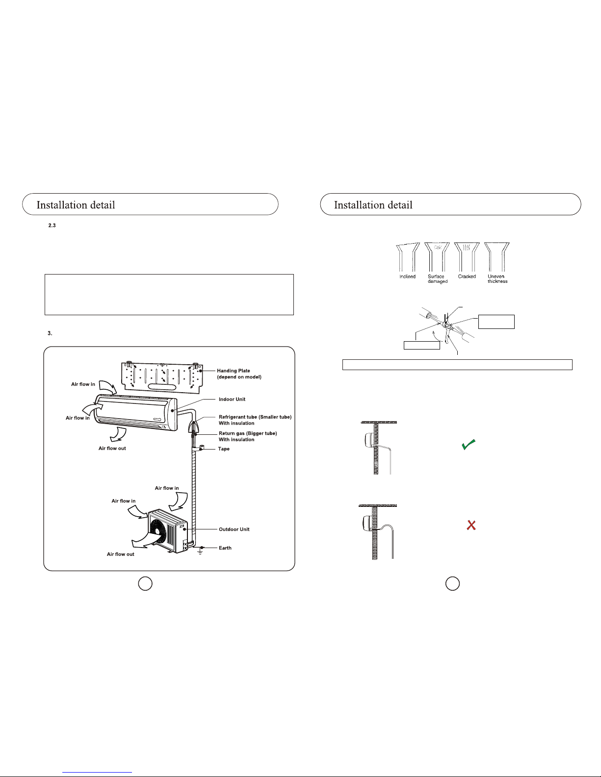
2.1 Indoor Unit
QMake sure that you installed the indoor unit in the good ventilation area and avoid to
blocking the both of the return air and the supply air.
Q Make sure that you installed the indoor unit in the area where there is no nearby source
of heat or vapor.
Q Make sure that you installed the indo or unit in the area that far from hot or cool air will
always spread in the room.
Q Make sure that you installed the indoor unit in an area thateasily to connecting with the
outdoor unit, and easily to drainage for condensed water.
Q The installed location sh ould be strong enough to hang the indoor unit and endurance
from vibration of indoor unit.
Q Should be have enough space around the indoor unit for ease of service.
Q The distance between indoor unit and outdoor unit should not exceed 10 meter and the
height different between indoor unitand outdoor unit should not exceed 4 meter, the
recommended distance is 5 meter.
2.2Outdoor Unit
QMake sure that you installed the outdoor unit in the area, which is not exposed to the rain
or direct sun light. (Should be added t o Installing for sunblind if exposed to direct sun
light.)
QMake sure that you install the outdoor unit inthe area allowing good air moment, which is
not amplifying for noise or vibration, especially to avoid disturbing neighbors. (Fix the unit
firmly if it is mounted in a high place.)
QMake sure that you install the outdoor Unit in the good ventilation area,has not dusty and
avoid to blocking the both of the fresh air and the outlet air.
Q Make sure that you install the outdoor unit inthe area free from animals or plants.
Q Make sure that you install the outdoor unit inthe area not blocking the traffic.
QMake sure that you install the outdoor unit in the area, which easily to drain for
condensed water from the indoor unit.
Q If necessary to install on a desk, d o not install in a direction that against the airflow from
the condensing unit. Working of air conditioner will be abnormal.
Q Do not let hot air flow into the condensing unit because the air conditioner will malfunction.
The hot air may come from another near-by condensing unit or heating equipment or itself.
Q If the condensing unit is installed in the direction such that the airflow goes directly
against a wall, the minimum distance between condensing unit and the wall is 1.5 meter
as show in the figure below.
Should
Indoor
N to
4 13
1.
2. Avoid tapping the power cord.
3.If necessary, extend the supplied plug cable. Using the recommended cable follow as table.
4. Pass the assembly cable through the rear of the indoor unit and plug the wired cable with the
supplied plug cable.
5. Pass the left end of cables through out the wall and gather with the refrigerant tubes and draining
pipe.
Recommended size of extensi on AC cord to the outdoor unit
Model
Connecting The Cable To The Out door Unit
4.7.
Use the end of the assembly cables from indoor unit connec ting to the terminal of outdoorunit
Grounding
4.8.
If the power distribution circuit does not have is earth, an earthing electrode must be
installed. The corresponding accessories are not supplied with the air conditioner.
1. Select an earthling electrode that its length at least1/2 meter.
2. Determine a suitable location for earthling electrode :
- Away from underground structures or facilities, such as gas pipes, water pipes, telephone
lines, underground cables and etc.
- At least 2 meters away from a lightening conductor earthling electrode and its cable.
3. Dig a hole of the size around 50 cm. width and 30 cm depth, drive theearthling electrode into the
position and cover the top of the electrode with the excavated soil.
4. Install a green/yellowinsulated earthling wire to the electrode.
5. Connect the earthling wire to theearthling screw on the outdoor unit.
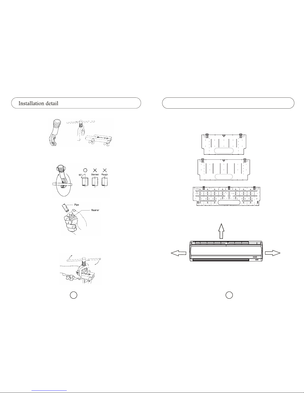
Vacuum Tube And Leakage Checking Procedure
4.9.
1. Use only the vacuum pump to take out the air from the system. Do not use any solvent. Take the
following steps.
¨After connecting the refrigerant tube between the indoor unit and the condensing unit,
connect the manifold gage to the arrow valve (blue cord) and vacuum pump (yellow cord).
¨ Operate the vacuum pump for ½ hour.
¨ Close the manifold gage and take out the vacuum pump.
1. Should separate one circuit breaker for one air conditioner only.
All AC cords unit in table is Sq.mm.
The extensiblecable, which connects between indoor and outdoor unit, is recommended 1 Sq.mm. at
least.
1. Remove the cover of outdoor unit.
2. Connect the assembly cable to the terminal following to wiring diagram.
3. Each wire is colored with the corresponding terminal number.
4. Replace the cover of outdoor unit.
9,000-13,000 15,000-18,000
25,000-26,000 30,000-34,000
2.5220Vac
380Vac
4 6 10
4
36,000-38,000 40,000-44,000 52,000-60,000
16
6 62.5

12 5
1 If the condensing unit is installed in a location that has an open airflow, the condensing unit
should be installed in a direction such that airflow out from the condensing unit is perpendicular to
the open air flow direction.
Open Air
Open Air
Air flow out
2
3
Fancoil unit
Condensing unit
Radius 5 cm.
Oil trap
( To condensing )
Space should be left around the condensing unit at least according to the figure for ease of installation,
service and ventilation.
4
Do not incline the condensing unit by more than 45 degrees.
5
Install the condensing unit on a rigid base.
6
Fasten the condensing unit to the base by using the nuts provided.
7
In the case of hanging the condensing, unit it should be hung on a rigid wall area and right angle steel
8
cm. thick should be used for the holder.
Put the rubber
under the nut.
Rigid wall
by using screws.
Right angle steel thick 4 cm.
Fasten right angle steel
4
If installed in a high temperature or humid area, the thickness of the pipe’s insulator should
be increased to 1/2” to protect the condensing water in the refrigerant tube.
If the condensing unit is installed higher than the indoor unit, an oil trap should be made as
show in picture
Water will drop
from indoor
unit.
INCORREC
T
End of drain pipe
is sunk in water.
3.00
cm.
Space is less
than 3.00 cm.
INCORREC
T
1. If necessary, the drain hose can be extended the drain pipe by connecting as following.
Pass the drain hose through the hole in the wall, making sure that the slop e downwards.
Pass drain hose under the refrigerant piping, taking care to keep the drain hose tight.
2.
3.

6 11
2.1 Remote Control Unit
1.Make sure that you install the remote control unit in an area free from obstacles such as curtains
etc, which may block signals from the remote control unit.
2. Make sure that you install the remote control unit in an area not exposed to direct sunlight, and
where there is no source of heat.
3. Make sure that you install the remote control unit in an area away from TVs, audio units, cordless
phones, and fluorescent lighting fixtures and other electrical appliances (at least 1-meter).
Caution:
It is harmful to the air conditioner if it is used in the following environments: greasy areas (including
near machines), salty areas such as coastal areas, areas where sulfuric gas is present such as hot
spring areas, areas where large var iations in supply voltage occur, such as factories. Contact your
dealer for advice.
Installation Diagram of Indoor Unitand Outdoor Unit
Check th at the flaring is correct, referring to the illustrations below for examples of incorrect flaring.
5.
Align the pipes to be connected and tighten the flare nuts first manual and then with a wrench.
6.
Connect the bigger tube first
Holding spanner
Must check this point that
is there any leak of refrigerant
Torque wrench
by using soapsuds.
Note:If outdoor unit is installed higher than indoor unit, should make oil trap. Refer to page 5.
Installingand Connectingthe Indoor Unit Drain Hose
The one most important point is installation the drain hose for the indoor unit to ensure
that any condensation water is correctly drained outside.
4.5
INCORRECT

10 7
150 mm
150 mm
120 mm
Use the hanging plate to mark position to punch for holding the indoor unit, and
making the hole for refrigerant tubes, draining pipe and cable that it slants slightly
downwards.
Fasten the hanging plate by using the screw.
Stretch out the refrigerant tubes and put it through the hole.
Hang the indoor unit on the hanging plate.
2.
1.
3.
4.
9,000-12,000 Btu/h
- The direction of the refrigerant tubes, drainpipe and the cable will be through out
which depend on the model of air conditioner.
- The position of indoor unit must place in the correct distance for easy
maintenance.
4. Indoor Unit & Outdoor Unit Installation
4.1 Fixing the Hanging Plate
Before fixing the hanging plate to the wall, the things must determine arefollowing:
- The hanging plate will be supplied which depend on model of indoor unit.
18,000-25,000 Btu/h
30 000-36,000 Btu/h,
1. Makesurethatyouhavetherequiredtoolsavailable.
If you wish to shorten the piping, cut it using a pipe cutter, taking care to ensure that the cut edge
remains at a 90° angle with the side of pipe, and referring to the illustrations below for examples of
edges cut correctly and incorrectly
1. To prevent any gas leaking out, remove all burrs at the cut end of the pipe, using a reamer.
1. Slide a flare nut on to the tube and modify the flare.
2.
3.
4.
Installation detail

8 9
Purgingthe Unit
4.2
On delivery, the indoor unit is loaded with an inert gas. All this gas must therefore be purged before
connecting the assembly piping.
1. Remove the caps at the end of each refrigerant tube the inert gas will escape from the
indoor unit.
During installation the inside tube should be cleanly, do not remove the caps until ready to connect
the tubes.
Installingand Connectingthe Refrigerant Tube
4.3
There are two refrigerant tubes of differingdiameters:
-A smaller one for the liquid refrigerant.
- A larger one for the gas refrigerant.
A short length of piping is already fitted to the air conditioner. You must extend this tube
using assembly tube.
Recommended size at the refrigerant tube
Model 09,000 12,000 18,000 25,000 30,000
Refrigerant
tube (inch) 1/4 1/4 3/8 3/8
Return gas
tube (inch) 1/2 1/2 1/2 5/8 5/8
1. With a knife, cut out the appropriate knockout piece on the rear of the indoor unit.
1.Smooth the cut edges.
1. Use flare connector to connect the refrigerant tube between the indoor unit and outdoor unit.
Note:If the tube must be extended, refer to cutting/extending the tube.
Cutting/Extending the tube
In recommended, the refrigerant tubes are not over than 5 m eters. If necessary, the
length can be up to 30 meters, but the refrigerant must be added to the circuit according tablebelow:
Class
Connection
Pipe Length
Air-purge
Method
At installation
Refrigerant
Adjustment
5m Max. Unnecessary
Refer to the detailed
Air-Purge Procedure
and Vacuum Tube Procedure
For o 1/4 tube adds 13 g.
Of refrigerant (R-410A)
for every 1 m.
For o 3/8 tube adds 58 g.
Of refrigerant (R-410A)
for every 1 m.
5-30m
3
6
5
4
7
Air outlet Air inlet
Drain hose
Water inlet
Plug for water tray
1/4
This manual suits for next models
2
Table of contents
Other Saijo Denki Air Conditioner manuals