Saimo 6101 Service manual

6101
6101
6101
6101 Belt
Belt
Belt
Belt Scale
Scale
Scale
Scale Integrato
Integrato
Integrato
Integrato r
r
r
r
Operating
Operating
Operating
Operating and
and
and
and Service
Service
Service
Service
Manual
Manual
Manual
Manual
VER 6.0
Saimo
Saimo
Saimo
Saimo Electric
Electric
Electric
Electric Co.,
Co.,
Co.,
Co., Ltd
Ltd
Ltd
Ltd

Declaration
This document is confidential and is the property of Saimo Electric. This document
may not be copied or reproduced in any way without the express written consent of
Saimo Electric. This document also is unpublished work of Saimo Electric. Saimo
Electric intends to and is maintaining the work as confidential information. Saimo
Electric also may seek to protect this work as published version. In the event of either
inadvertent or deliberate publication, Saimo Electric intends to enforce its rights to
this work under the copyright laws as a published work. Those having access to this
work may not copy, use or disclose the information in this work unless expressly
authorized by Saimo Electric.
Saimo Electric will not make any guarantee on this manual, and be free liability on
any print mistake or misunderstanding by user.
If there is any difference from equipment ordered in this manual, Saimo Electric
reserves its final explanation right.
If any changes made on this manual, which will not be informed individually.

6101
6101
6101
6101 Belt
Belt
Belt
Belt Scale
Scale
Scale
Scale Integrator
Integrator
Integrator
Integrator Operating
Operating
Operating
Operating and
and
and
and Service
Service
Service
Service Manual
Manual
Manual
Manual
2
Thanks for purchasing Saimo Electric products.
This manual guides you through the application of your selected products, covering
the information necessary for installation, operation, maintenance and service. If there
is any question found during operation, please dial Saimo Electric customer service
phone# at 0516-87885866 for support. Thanks for your kind understanding and
support.
Please read and observe the following safety precautions found throughout this
manual and be strict in execution, which will help to protect equipment from damage,
prolong equipment life time, and guarantee your normal usage and maintenance and
person safety.
· Please read through all the documents dispatched together with the equipments!
· For the sake of personal safety and normal operation of the equipments, it is
imperative to assure that only the designed AC power supply is to be used. Reliable
3-pin earthed power outlets must be used to avoid electric shock when touching the
enclosure. Ensure that the rated voltage of the display or other peripheral devices is
compatible with your local AC power requirements.
· The equipment must be protected against thunderstrike.
· Disconnect all the cables from the equipment before you attempt to move the
equipment. Do not attempt to move any components on the equipment when
equipment is powered on.
· Do not attempt to change any components or external connections on the equipment
before the equipment is powered off.
· Avoid inadvertent power interruption during normal operation.
· Only qualified technicians can be allowed to open the enclosure of the equipment.
· keep the equipment from moisture. Shut off power from the equipment immediately
if it is splashed with water or other liquids occasionally.

6101
6101
6101
6101 Belt
Belt
Belt
Belt Scale
Scale
Scale
Scale Integrator
Integrator
Integrator
Integrator Operating
Operating
Operating
Operating and
and
and
and Service
Service
Service
Service Manual
Manual
Manual
Manual
2
CATALOGUE
CATALOGUE
CATALOGUE
CATALOGUE OF
OF
OF
OF CHART
CHART
CHART
CHART .................................................................................................................
.................................................................................................................
.................................................................................................................
................................................................................................................. VI
VI
VI
VI
CHAPTER
CHAPTER
CHAPTER
CHAPTER 1
1
1
1 INTRODUCTION
INTRODUCTION
INTRODUCTION
INTRODUCTION .........................................................................................................
.........................................................................................................
.........................................................................................................
......................................................................................................... 1
1
1
1
1.1 G ENERAL ......................................................................................................................................... 1
1.2
T
ECHNICAL SPECIFICATIONS ............................................................................................................ 2
1.3 F EATURES ........................................................................................................................................ 3
1.3.1 Measuring Function .............................................................................................................. 4
1.3.2 Monitoring Function .............................................................................................................. 5
1.3.3 Printing Function ................................................................................................................... 5
1.3.4 Communications (Optional) ................................................................................................. 6
1.4
W
ARRANTY ...................................................................................................................................... 7
1.5 UNPACKING AND INSPECTION ................................................................................................................. 8
1.6 STORAGE ............................................................................................................................................. 8
1.7 SYMBOL .............................................................................................................................................. 8
1.8 H ARDWARE INSTRUCTION ................................................................................................................ 8
1.8.1 Housing .................................................................................................................................... 8
1.8.2 Ambient Condition ............................................................................................................... 8
1.8.3 Power Requirements ................................................................................................................ 8
1.8.4 Speed sensor input ................................................................................................................... 9
1.8.5 Digital I/O Board ( Figure 1-5 ).................................................................................... 10
1.8.6 Load cell input ....................................................................................................................... 13
1.8.7 Analog I/O Board ............................................................................................................... 13
1.8.8 Comm. Board ......................................................................................................................... 13
CHAPTER
CHAPTER
CHAPTER
CHAPTER 2
2
2
2 INTEGRATOR
INTEGRATOR
INTEGRATOR
INTEGRATOR INSTALLATION
INSTALLATION
INSTALLATION
INSTALLATION .............................................................................
.............................................................................
.............................................................................
............................................................................. 14
14
14
14
2.1 G ENERAL ....................................................................................................................................... 14
2.2 6101 I NTEGRATOR
I
NSTALLATION ................................................................................................. 14
2.2.1 Mounting ................................................................................................................................ 14
2.2.2 Safety Precautions .............................................................................................................. 18
2.2.3 Wiring (External Power Supply) ........................................................................................ 19
2.2.4 Input voltage setup ......................................................................................................... 20
2.2.5 Serial Communication ....................................................................................................... 20
2.2.6 Load cell ............................................................................................................................. 22
2.2.7 Integrator analog board ..................................................................................................... 22
2.2.8 Integrator CPU board ........................................................................................................... 24
2.2.9 Digital input/output board ..................................................................................................... 25
2.2.10 Wiring .................................................................................................................................. 26
CHAPTER
CHAPTER
CHAPTER
CHAPTER 3
3
3
3OPERATION
OPERATION
OPERATION
OPERATION ......................................................................................................................
......................................................................................................................
......................................................................................................................
...................................................................................................................... 27
27
27
27
3.1 R UN MENU .................................................................................................................................... 27
3.1.1 General .................................................................................................................................. 27
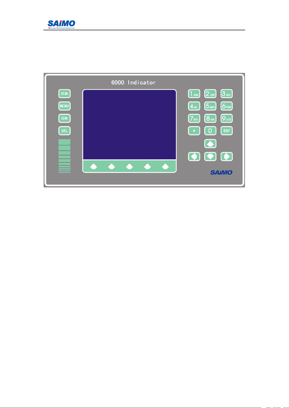
3.1.2 Front panel ............................................................................................................................ 27
3.1.3 Keyboard ............................................................................................................................... 27
3.1.4 Quick setup method ............................................................................................................... 28
3.1.5 Menu display .......................................................................................................................... 29

6101
6101
6101
6101 Belt
Belt
Belt
Belt Scale
Scale
Scale
Scale Integrator
Integrator
Integrator
Integrator Operating
Operating
Operating
Operating and
and
and
and Service
Service
Service
Service Manual
Manual
Manual
Manual
2
3.1.6 Reset total .............................................................................................................................. 30
3.1.7 Alarm Menu ........................................................................................................................... 32
3.2 M AIN MENU .................................................................................................................................. 32
3.2.1 Initial Setup Menu ............................................................................................................... 33
3.2.2 System calibration ................................................................................................................. 47
3.2.3 System data setup ................................................................................................................... 58
3.2.4 “ Simulated constant ” calculation .......................................................................................... 63
3.2.5 Input/output setup .................................................................................................................. 64
3.2.6 Communication Menu ........................................................................................................ 73
3.2.7 Alarm Setup Menu .............................................................................................................. 76
3.2.8 Loadout Setup Menu .......................................................................................................... 80
3.2.9 Password Setup Menu ............................................................................................................ 81
3.2.10 Diagnostics Menu ............................................................................................................. 84
3.2.11 Statistics Menu .................................................................................................................. 85
CHAPTER
CHAPTER
CHAPTER
CHAPTER 4.0
4.0
4.0
4.0 INTEGRATOR
INTEGRATOR
INTEGRATOR
INTEGRATOR MAINTENANCE
MAINTENANCE
MAINTENANCE
MAINTENANCE ...........................................................................
...........................................................................
...........................................................................
........................................................................... 88
88
88
88
4.1 S ERVICE AND REPAIRING .............................................................................................................. 88
4.2 DAILY MAINTENANCE ROUTINES OF 6101 I NTEGRATOR .............................................................. 88
4.3
T
ROUBLESHOOTING --- F AULT ISOLATION ................................................................................... 88
4.3.1 Power Supply Examination ................................................................................................ 90
4.3.2 Speed Input .......................................................................................................................... 90
4.3.3 Load Cell Input .................................................................................................................... 90
4.3.4 Current Output (Optional) .................................................................................................. 92
4.3.5 Constant Setup .................................................................................................................... 94
4.4 U SUAL
T
ROUBLESHOOTING ........................................................................................................... 94
APPENDIX
APPENDIX
APPENDIX
APPENDIX 1
1
1
1PERMANENT
PERMANENT
PERMANENT
PERMANENT FIELD
FIELD
FIELD
FIELD RECORD
RECORD
RECORD
RECORD .............................................................................
.............................................................................
.............................................................................
............................................................................. 95
95
95
95

6101
6101
6101
6101 Belt
Belt
Belt
Belt Scale
Scale
Scale
Scale Integrator
Integrator
Integrator
Integrator Operating
Operating
Operating
Operating and
and
and
and Service
Service
Service
Service Manual
Manual
Manual
Manual
2
C
C
C
C atalogue
atalogue
atalogue
atalogue of
of
of
of Chart
Chart
Chart
Chart
FIGURE 1-1 6101 B
ELT
SCALE INTEGRATOR –
P
ANEL MOUNT ..................................................................... 1
FIGURE 1-2 6101 B ELT SCALE INTEGRATOR – F IELD MOUNT ..................................................................... 2
FIGURE 1-3 6101 BELT SCALE INTEGRATOR FRONT PANEL ........................................................................ 4
FIGURE 1-4 SPEED SENSOR INNER WIRING DRAWING ............................................................................... 10
FIGURE 1-5 D IGITAL INPUT INNER WIRING DRAWING ............................................................................... 11
FIGURE 1-6 D IGITAL OUTPUT INNER WIRING DRAWING ........................................................................... 12
FIGURE 1-7 DC SOLID
STATE
RELAY WIRING DRAWING ........................................................................... 12
FIGURE 1-8 AC STATE RELAY WIRING DRAWING ...................................................................................... 12
FIGURE 1-9 A NALOG INPUT INTERIOR WIRING DRAWING ......................................................................... 13
FIGURE 2-1 S CALE BRIDGE INSTALLATION ILLUSTRATION ...................................................................... 14
FIGURE 2-2 M ETAL HOUSING 6101 F IELD MOUNTING INTEGRATOR OUTLINE DIMENSION AND MOUNTING
DIMENSION ...................................................................................................................................... 15
FIGURE 2-3 P LASTIC HOUSING 6101 F IELD MOUNTING INTEGRATOR OUTLINE DIMENSION AND
MOUNTING DIMENSION .................................................................................................................... 16
FIGURE 2-4 6101 P ANEL MOUNTING INTEGRATOR OUTLINE DIMENSION AND MOUNTING DIMENSION .... 18
FIGURE 2-5 6101 INTEGRATOR MOTHER BOARD ...................................................................................... 20
FIGURE 2-6 6101 SERIAL COMM .BOARD ................................................................................................. 21
FIGURE 2-7 RS-485 MULTI -STATE COMM . C ONNECTION ILLUSTRATION .................................................. 21
FIGURE 2-8 6101 INTEGRATOR LOAD CELL A/D BOARD ........................................................................... 22
FIGURE 2-9 6101 I NTEGRATOR
A
NALOG I/O B OARD ............................................................................... 23
FIGURE 2-10 6101 I NTEGRATOR EXTENDING ANALOG BOARD ................................................................. 24
FIGURE 2-11 6101 I NTEGRATOR CPU BOARD .......................................................................................... 24
FIGURE 2-12 6101 I NTEGRATOR DIGITAL INPUT /OUTPUT BOARD ............................................................ 25
FIGURE 2-13 6101 I NTEGRATOR DIGITAL INPUT /OUTPUT BOARD SETUP .................................................. 25
FIGURE 2-14 6101 INTEGRATOR WIRING DRAWING .................................................................................. 26
FIGURE 3-1
K
EY ARRANGEMENT ............................................................................................................. 27
FIGURE 3-2 S AIMO BELT SCALE BRIDGE ................................................................................................. 38
FIGURE 3-3 P
IVOT
TO LOADCELL DISTANCE PTO
L
.................................................................................. 39
FIGURE 3-4 P
IVOT
TO 1
ST
WEIGH IDLER DISTANCE PTO 1ST ..................................................................... 39
FIGURE 3-5 P
IVOT
TO 2ND WEIGH IDLER DISTANCE ................................................................................. 40
FIGURE 3-6 P
IVOT
TO 1
ST
, 2
ND
, 3
RD
,FORTH IDLER DISTANCE ................................................................. 40
FIGURE 3-7 P
IVOT
TO TEST WEIGHT HEIGHT ............................................................................................. 40
FIGURE 3-8 P
IVOT
TO TEST WEIGHT DISTANCE ......................................................................................... 41
FIGURE 3-9 P
IVOT
TO SCALE CARRIAGE HEIGHT ...................................................................................... 41
FIGURE 3-10 P ULLEY TO SCALE CARRIAGE HEIGHT ................................................................................. 42
FIGURE 3-11 C
ONVEYOR
’
S ANGLE OF INCLINE ......................................................................................... 42
FIGURE 4-1 6101 I NTEGRATOR
T
ROUBLESHOOTING FLOW CHART .......................................................... 89
FIGURE 4-2
T
ROUBLESHOOTING THE SPEED INPUT ................................................................................. 90
FIGURE 4-3
T
ROUBLESHOOTING
L
OAD CELL INPUT ................................................................................ 91
FIGURE 4-4
T
ROUBLESHOOTING CURRENT OUTPUT ................................................................................ 93

6101
6101
6101
6101 Belt
Belt
Belt
Belt Scale
Scale
Scale
Scale Integrator
Integrator
Integrator
Integrator Operating
Operating
Operating
Operating and
and
and
and Service
Service
Service
Service Manual
Manual
Manual
Manual
2
Chapter
Chapter
Chapter
Chapter 1
1
1
1 Introduction
Introduction
Introduction
Introduction
1.1
1.1
1.1
1.1 General
General
General
General
Feeder electric belt scale is a measuring equipment that continuously auto weighs
material which is continuously passing through the conveyor with features of continue
and auto. Automatic operation is achieved without intervention of the operator.
Feeder electric belt scale is mainly consisted of:load cell, weighing bridge, secondary
integrator three main parts. Integrator 6101 is secondary feeder part.
This manual provides the information you need for performance, installation,
operation, and maintenance of the 6101 belt scale integrator.
The 6101 integrator is available in panel mount (figure 1-1) and field mount (figure
1-2). By processing the weight signal from the load cell and the speed signals from
the speed sensor, It calculates and displays flow rate and total of the material fed.
Figure 1- 1 6101 Belt scale integrator – Panel mount

6101
6101
6101
6101 Belt
Belt
Belt
Belt Scale
Scale
Scale
Scale Integrator
Integrator
Integrator
Integrator Operating
Operating
Operating
Operating and
and
and
and Service
Service
Service
Service Manual
Manual
Manual
Manual
2
Figure 1- 2 6101 Belt scale integrator – Field mount
1.2
1.2
1.2
1.2 Technical
Technical
Technical
Technical Specifications
Specifications
Specifications
Specifications
(a) Chinese / English menu

6101
6101
6101
6101 Belt
Belt
Belt
Belt Scale
Scale
Scale
Scale Integrator
Integrator
Integrator
Integrator Operating
Operating
Operating
Operating and
and
and
and Service
Service
Service
Service Manual
Manual
Manual
Manual
2
(b) Weighing Capability
· The 6101 integrator is capable of connecting up to eight 350 Ω loads and
acquiring a speed signal from the speed sensor, to calculate flow rate and
total.
· The 6101 integrator has the function of automatic zero calibration.
(c) Ambient Environment
· Location: Indoor or outdoor, as close as possible to the load cells, free from
damp and dust.
· Temperature:
Storage temperature : -40~+70 º C
Operati ng temperature : -10~+50 º C
· Max imum Relative Humidity: 95%
(d) Power Requirements
· 220VAC ± 10% or 110VAC ± 10% 50Hz
· Fuse: 2A
· EMI / RFI filter
(e) Load Cell
· offers 10VDC (+/- 10% ), 5 00mA excited power , up to 8 load cell
s
· Sensitivity : 0.5mV/V ~ 3.5mV/V
· Max. input signal 33mV
· Load cell shield grounding
· E xcitation compensation circuit is employed when the cable distance is over 60
meters but less than 900 meters .
· Local or remote compensation can be selected by a jumper set.
(f) Mainboard Digital Input
The mainboard provides 8 programmable inputs for receiving dry contact on-off
signal
(g) Mainboard Digital Output
The mainboard provides 8 programmable outputs.
In which the eighth output is solid state relay output, for user optional.
either AC output (24~280V AC, 3A) or DC output (5~60VDC, 3A).
The other outputs are transistor OC outputs (24VDC, 0.5A).
(h) Housing Outline Dimensions
Panel mount: Metal housing
Field mount: Metal housing and plastic housing both are available.
Protection, IP65
See Chpater 2 for mounting dimension drawing (figure 2-1, 2-3,
2-4)
1.3
1.3
1.3
1.3 Features
Features
Features
Features
Saimo 6101 integrator is specially designed for belt scales, meeting all measuring and
control requirements on typical applications.
The software has been solidified into the memory chip. Each preprogrammed function
can be activated automatically by operating from the keypad or installing the optional
expansion board.
Saimo 6101 integrator has a powerful and user friendly operating interface, easy for
function selection, data setup, operation and maintenance.
The following functions have been completed into Saimo 6101 integrator.

6101
6101
6101
6101 Belt
Belt
Belt
Belt Scale
Scale
Scale
Scale Integrator
Integrator
Integrator
Integrator Operating
Operating
Operating
Operating and
and
and
and Service
Service
Service
Service Manual
Manual
Manual
Manual
2
· Measuring
· Monitoring
· Printing
· Communication
Figure 1- 3 6101 belt scale integrator front panel
1.3.1
1.3.1
1.3.1
1.3.1 Measuring
Measuring
Measuring
Measuring Function
Function
Function
Function
1. Instantaneous Flowrate Calculation
The signal delivered by the load cell(s), which represents the weight per unit length of
the belt(kg/m), is multiplied by the signal delivered by the speed sensor which
represents the belt speed (m/s). The result of this operation is the instantaneous
flowrate (kg/m x m/s=kg/s) which is then multiplied by suitable constant to obtain the
value in the required engineering units (kg/h or ton/h, etc.). An adjustable damping
filter is provided separately for displayed rate and current outputs.
2. Flow Totalization
The total is accumulated by multiplying mass per unit length by incremental length
and totalizing the result in engineering units.
3. Zero and Span Automatic Calibration
Zero and span calibrations are based on belt length defined by a number of belt
revolutions.
To calculate the exact number of revolutions, the instrument counts the pulses
delivered by the speed sensor (one pulse represents a specific belt length); when the
required number of pulses is reached, the instrument ends the calibration test, and
compares the actual totalized value to the theoretical one (0 for zero calibration), and
calculates the calibration constant.
The calibration constant is a calculated value that can be factored based on an actual
material test.
· Electronic Calibration (R-Cal)
Allows the operator to perform the calibration without the need of applying test

6101
6101
6101
6101 Belt
Belt
Belt
Belt Scale
Scale
Scale
Scale Integrator
Integrator
Integrator
Integrator Operating
Operating
Operating
Operating and
and
and
and Service
Service
Service
Service Manual
Manual
Manual
Manual
2
weights or test chain on the weighbridge. The electronic calibration checks all the
circuitry including the load cell, and is performed by unbalancing the load cell
bridge using a precision resistor. The calibration constant is calculated on the basis
of the load cell and the scale data.
· Test Weight Calibration
Requires the positioning of test weights on the weighbridge
· Chain Calibration
Requires the application of calibrated chains on the belt. This method is the
nearest to actual operating conditions.
· Material Calibration
Is performed by running a known quantity of material on the scale and weighing
that quantity on a static scale of known accuracy.
4. Zero Tracking (AZT)
Under a preset minimum flowrate when enabled, the instrument makes subsequent
automatic zero calibrations with the following sequence:
· performs automatic zero for one test duration.
· continuously repeats above zero calibration as long as feed rate remains below AZT
preset value.
“ Zero Tracking ” has Max. “ Tracking range ” , which is setup with % in “ System
data ” Menu .
5. Current Output Signals
An optional current output/analog input board is available. Each current output may
be programmed via the keyboard to deliver one of the following signals:
· flowrate
· belt loading
· belt speed
1.3.2
1.3.2
1.3.2
1.3.2 Monitoring
Monitoring
Monitoring
Monitoring Function
Function
Function
Function
Saimo 6101 integrator is equipped with an indication system. Indication can be in the
form of:
· status indications
· process alarms
· programming errors
· equipment failures
The integrator includes internal diagnostics that will generate alarms in case of
hardware failures or programming errors. The following process alarms are also
provided:
· Belt slip (two speed sensors recommended)
· Alarms for high and low flowrate, speed and weight
These alarms are visible on the display and can be acknowledged and reset through
keyboard, digital input or serial line. Alarms can be delayed to avoid intervention in
case of short time peaks. Each individual alarm can be programmed to operate as
alarm, shut down or to be ignored.
1.3.3
1.3.3
1.3.3
1.3.3 Printing
Printing
Printing
Printing Function
Function
Function
Function
Periodical and under command prints can be obtained by connecting a serial printer to
an optional communication board.

6101
6101
6101
6101 Belt
Belt
Belt
Belt Scale
Scale
Scale
Scale Integrator
Integrator
Integrator
Integrator Operating
Operating
Operating
Operating and
and
and
and Service
Service
Service
Service Manual
Manual
Manual
Manual
2
1.3.4
1.3.4
1.3.4
1.3.4 Communications
Communications
Communications
Communications (Optional)
(Optional)
(Optional)
(Optional)
· Serial Communications
The communication protocol allows a remote intelligent device to read and
eventually write the contents of the registers.
During the communication activity, the 6101 integrator always acts as a Slave,
meaning it responds to a request from a Master device on the line, but never attempts
to send messages out.

6101
6101
6101
6101 Belt
Belt
Belt
Belt Scale
Scale
Scale
Scale Integrator
Integrator
Integrator
Integrator Operating
Operating
Operating
Operating and
and
and
and Service
Service
Service
Service Manual
Manual
Manual
Manual
2
1.4
1.4
1.4
1.4 Warranty
Warranty
Warranty
Warranty
Saimo Electric Warranty
The seller warrants that the equipment delivered hereunder shall be free from defects
in material and workmanship. Such warranty shall not apply to accessories, parts, or
material purchased by the seller unless they are manufactured pursuant to seller ’
s
design, but shall apply to the workmanship incorporated in the installation of such
items in the complete equipment. To the extent purchased parts or accessories are
covered by the manufacturer ’
s
warranty, seller shall extend such warranty to buyer.
Seller
’
s
obligation under said warranty is conditioned upon the return of the defective
equipment, transportation charges prepaid, to the seller
’
s
factory and the submission
of reasonable proof to seller prior to return of the equipment that the defect is due to a
matter embraced within seller
’
s
warranty hereunder. Any suh defect in material and
workmanship shall be presented to seller as sonn as alleged errors or defects are
discovered by purchaser and seller is given opportunity to investigate and correct
alleged errors or defects and in all cases. The whole equipment warranty period will
be 12 months, within this period, the seller will replace any parts and components
which are not damaged by the seller
’
s
unproper operation at free charge.
Said warranty shall not apply if the equipment shall not have been operated and
maintained in accordance with seller
’
s
written instructions applicable to such
equipment, or if such equipment shall have been repaired or altered or modified
without seller
’
s
approval.
Field Service
Purchaser agrees to underwrite the cost of any labor required for replacement;
including time, travel and living expenses of Saimo Field Service engineer at closest
factory base, altered or modified
Saimo
Saimo
Saimo
Saimo Electric
Electric
Electric
Electric Share
Share
Share
Share Holding
Holding
Holding
Holding Company
Company
Company
Company

6101
6101
6101
6101 Belt
Belt
Belt
Belt Scale
Scale
Scale
Scale Integrator
Integrator
Integrator
Integrator Operating
Operating
Operating
Operating and
and
and
and Service
Service
Service
Service Manual
Manual
Manual
Manual
2
1.
1.
1.
1. 5
5
5
5Unpacking and inspection
Saimo Model 6101 integrator has been properly packaged for shipment and storage.
Optional equipment unpacking, please see annex for instruction.
Inspect all packages for damage before opening as oftentimes the carrier may be
responsible for shipping damage. Optional equipment inspection, see annex for
instruction please.
1.
1.
1.
1. 6
6
6
6Storage
6101 integrator can be safely stored with cover latches secured and hole plugs
installed, between -40
℃—
+70
℃
. The units should be protected against moisture.
1.
1.
1.
1. 7
7
7
7Symbol
Symbol
Symbol
Symbol
Symbol Instruction
Instruction
Instruction
Instruction
Symbol Description
AC
Grounding end
Shielded grounding
Warn, power
Warn
1.8
1.8
1.8
1.8 Hardware
Hardware
Hardware
Hardware instruction
instruction
instruction
instruction
1.8.1
1.8.1
1.8.1
1.8.1 Housing
Housing
Housing
Housing
See Chapter 2 for Installation dimension drawing (Figure 2-1, 2-3, 2-4)
1.8.2
1.8.2
1.8.2
1.8.2 Ambient Condition
·Location: Indoor or outdoor, as close as possible to the load cells, free from
damp and dust.
·Temperature:
Storage temperature : -40~+70 º C
Operati ng temperature -10~+50 º C
·Max imum Relative Humidity: 95%
·Pollution Degree: pollution II
·Elevation: 2000m
1.8.3
1.8.3
1.8.3
1.8.3 Power
Power
Power
Power Requirements
Requirements
Requirements
Requirements
·110/220/240
VAC
,+10%,-15%;50/60Hz,select via switch on mainboard
·Fuse: 0.5A Φ5mmX20mm
·EMI / RFI filter

6101
6101
6101
6101 Belt
Belt
Belt
Belt Scale
Scale
Scale
Scale Integrator
Integrator
Integrator
Integrator Operating
Operating
Operating
Operating and
and
and
and Service
Service
Service
Service Manual
Manual
Manual
Manual
2
1.8.4
1.8.4
1.8.4
1.8.4 Speed
Speed
Speed
Speed sensor
sensor
sensor
sensor input
input
input
input
1、High speed digital (DC)input
— Speed sensor (Figure 1 — 4 )
— comparator with hysteresis loop
— photoelectricity isolation
— Built in current source used for mechanical contact
— power supplied by +24V DIO
— type:
Voltage/current or contact type sensor
Apply to all SAIMO sensors
— frequency range
:
— Voltage/current type sensor :0.25 — 2.0 kHz
— contact type sensor :0.25 — 30 Hz
— Low threshold :+1.0 Vdc (Min. )
— high threshold :+3.2 Vdc (Max. )
— Low or high pulse cycle
:
— Voltage/current type sensor :200 us (Min. )
— Contact type sensor :15 ms (Min. )
— hysteresis loop :0.5 Vdc (Min. )
— input resistance
:
10 k Ω
(
typical
)
500 Ω (Min. )
— input current :- 2 mA (at 0 Vdc )
— Max. safety input voltage :
Peak value :± 50V , continuous voltage
— cable length:1.6 km ,use 18AWG shielded cable.

6101
6101
6101
6101 Belt
Belt
Belt
Belt Scale
Scale
Scale
Scale Integrator
Integrator
Integrator
Integrator Operating
Operating
Operating
Operating and
and
and
and Service
Service
Service
Service Manual
Manual
Manual
Manual
2
Figure 1- 4 speed sensor inner wiring drawing
1.8.5
1.8.5
1.8.5
1.8.5 Digital I/O Board ( Figure
Figure
Figure
Figure 1-5
1-5
1-5
1-5 )
·Main board Digital Input
(a) The main board provides 8 programmable inputs (including two way speed
inputs)for receiving dry contact on-off signal. Input can be defined as below by
user:
Batch ready
Batch run
System run
Total reset
Alarm reset
Auto zero

6101
6101
6101
6101 Belt
Belt
Belt
Belt Scale
Scale
Scale
Scale Integrator
Integrator
Integrator
Integrator Operating
Operating
Operating
Operating and
and
and
and Service
Service
Service
Service Manual
Manual
Manual
Manual
2
Figure 1- 5 Digital input inner wiring drawing
· Main board Digital Output
The main board provides 8 programmable outputs. Among of them, the 8
th
output
is relay output, optional for user, AC output (24~280V AC, 3amps) or DC
output (5`60V DC, 3amps) can be defined. The others are 0Coutput
24VDC,0.5amps).
Output can be defined as below by user:
High flow rate
Low flow rate
High load
Low load
High speed
Low speed
Slippage
Total output
Batch begin
Batch end
Volume measuring
ready
system error

6101
6101
6101
6101 Belt
Belt
Belt
Belt Scale
Scale
Scale
Scale Integrator
Integrator
Integrator
Integrator Operating
Operating
Operating
Operating and
and
and
and Service
Service
Service
Service Manual
Manual
Manual
Manual
2
Figure 1- 6 Digital output inner wiring drawing
Figure 1- 7 DC solid state relay wiring drawing
Figure 1- 8 AC state relay wiring drawing

6101
6101
6101
6101 Belt
Belt
Belt
Belt Scale
Scale
Scale
Scale Integrator
Integrator
Integrator
Integrator Operating
Operating
Operating
Operating and
and
and
and Service
Service
Service
Service Manual
Manual
Manual
Manual
2
1.8.6
1.8.6
1.8.6
1.8.6 Load
Load
Load
Load cell
cell
cell
cell input
input
input
input
Load Cell
· integrator supplies 10VDC ± 10% ,500mA excitation power supply, for parallel
connection of up to 8 load cells.
· Sensitivity 0.5mV/V – 3.5mV/V
· Max. input signal 33mV
· Load cell shield grounding
· E xcitation compensation circuit is employed when the cable distance is over 60
meters but less than 900 meters . Local or remote compensation can be selected by a
jumper set.
1.8.7
1.8.7
1.8.7
1.8.7 Analog I/O Board
Current input (Figure 1-9)
· photoelectric isolation
· separate power supply
· change into voltage input by adding one inner resistor
· Input range: optional 20-4mA or 4-20mA, representing 0 to 100% variable.
· Resistance load: Max. 800ohm
· Capacitance load: no limit
Figure 1- 9 Analog Input interior wiring drawing
1.8.8
1.8.8
1.8.8
1.8.8
Comm. Board
· photoelectric isolation
· 2 way serial port
· RS232 / RS485 jumper selection
· RS-232 Max. distance transmitted: 12m
;
RS-485 Max. distance transmitted:1200 m
· Up to 32 integrators made up of RS-485 metwork (if much more needed, it can be
customized

6101
6101
6101
6101 Belt
Belt
Belt
Belt Scale
Scale
Scale
Scale Integrator
Integrator
Integrator
Integrator Operating
Operating
Operating
Operating and
and
and
and Service
Service
Service
Service Manual
Manual
Manual
Manual
14
Chapter
Chapter
Chapter
Chapter 2
2
2
2 Integrator
Integrator
Integrator
Integrator Installation
Installation
Installation
Installation
2.1
2.1
2.1
2.1 General
General
General
General
This chapter contains the information about the installation procedures, hardware
configuration and intial programme of 6101 integrator. During intial programme, operator
must input necessary conveyor and belt scale data. After data input, integrator can proceed
auto zero, span calibration.
2.2
2.2
2.2
2.2 6101
6101
6101
6101 Integrator
Integrator
Integrator
Integrator Installation
Installation
Installation
Installation
The 6101 integrator must be installed indoors, not be exposed to excessive vibration, heat or
moisture.
The panel mount integrator should be installed in a control panel. After installation,
dustproof measures should be taken for the front panel of the integrator and the control
cabinet. (figure 2-2)
Figure 2- 1 Scale bridge installation illustration
2.2.1
2.2.1
2.2.1
2.2.1 Mounting
Mounting
Mounting
Mounting
The 6101 field mount feeder controller can be vertically secured to the rigid and flat wall
through the 4 mounting holes at the back of the enclosure. Care should be taken to insure the
mounting surface is flat so as not to twist or warp the fiberglass enclosure when tightening
the mounting holes.
The 6101 panel mount integrator should have a clearance of at least 5cm at the top and
bottom to allow air circulation. In case that the integrator must be positioned under the heat
sources, proper space around the integrator should be reserved. Sufficient space should be
kept behind the integrator to facilitate wiring and changing fuse. The side clearance should
be easy for securing the holding brackets after the 6101 has been put in place. Disconnect
power supply from the integrator when mounting the bracket. From the back, insert the
Table of contents