Salcom 12-88-7000 User manual

Copyright © 2017 Sea Air and Land Communications Ltd. All rights reserved.
12-88-7000
Output Control Receiver
PRODUCT MANUAL
Version 1.02
July 2017

P a g e | 1
12-88-7000 OUTPUT CONTROL RECEIVER
Product Manual
Sea Air and land Communications Ltd, 10 Vanadium Place, Addington, Christchurch 8024, New Zealand July 2017
Salcom Product Documentation
This document is designed to familiarise you with Salcom products and guide you through the
hardware, configuration, installation and overall system management.
Salcom is an environmentally conscious company and in an effort to conserve paper no longer
prints manuals with shipped products. All relevant documentation can be downloaded in PDF
form from our website www.salcom.com

P a g e | 2
12-88-7000 OUTPUT CONTROL RECEIVER
Product Manual
Sea Air and land Communications Ltd, 10 Vanadium Place, Addington, Christchurch 8024, New Zealand July 2017
Warranty and Disclaimer
Salcom products are warranted for a period of 12 months from the date of purchase against
faulty materials and workmanship. Should any fault occur the unit should be returned to the
vendor, freight pre-paid. Please include a description of the fault to assist with prompt return.
Any unauthorised alterations or repairs will invalidate the warranty.
All information provided in this document is carefully prepared and offered in good faith as a
guide in the installation, use and servicing of Salcom products. Installers must ensure that the
final installation operates satisfactorily within the relevant regulatory requirements. Salcom
accept no responsibility for incorrect installation. We reserve the right to change products,
specifications and installation data at any time without notice

P a g e | 3
12-88-7000 OUTPUT CONTROL RECEIVER
Product Manual
Sea Air and land Communications Ltd, 10 Vanadium Place, Addington, Christchurch 8024, New Zealand July 2017
Product Overview
The 12-88-7000 is a high sensitivity VHF/UHF paging receiver which is able to control 3 outputs
(one relay and two as open collector). It operates over the two frequency ranges, VHF 148Mhz
to 165MHz (model 12-88-7150) and UHF 440Mhz to 470MHz (model 12-88-7450). The 12-88-7000
decodes 512 or 1200 baud, alphanumeric or numeric Salcom control protocol messages.
By default the 12-88-7000 is configured to use an internal PCB aerial, but an indoor external
aerial (SMA) can be used if required. If the application requires an outdoor external aerial, the
Salcom 12-84-7000 is a more suitable receiver.

P a g e | 4
12-88-7000 OUTPUT CONTROL RECEIVER
Product Manual
Sea Air and land Communications Ltd, 10 Vanadium Place, Addington, Christchurch 8024, New Zealand July 2017
Installation and Connections
Situate the 12-88 away from direct sunlight, vibration and strong heat sources, and avoid close
proximity to radio transmission equipment. The unit is not certified as intrinsically safe.
In reasonable coverage areas an aerial will not need to be fitted - the internal PCB aerial will
perform well in most situations.
Connect a 12 volt DC power supply to the power pins (pins 1 and 2). The 12-88 is protected
against reversed supply connection. The power source must be reasonably noise free.
The connections to the relay contacts are made using pins 6(normally open contact), 7(relay
common) and 8(normally closed contact). The relay is not to be connected directly to mains
voltages.
Open collector outputs (pins 3 and 4) can be used to sink up to 80mA. The open collector
outputs can be easily damaged if used incorrectly. These outputs are well suited for low current
applications, or being used to control larger switchgear (with suitable protection).
Pin numbering: looking into the sockets, pin 1 is on the left.
Pin
Description
1
+12V
2
GND
3
Output 3
4
Output 2
5
Do not connect
6
Relay Normally Open
7
Relay Common
8
Relay Normally Closed

P a g e | 5
12-88-7000 OUTPUT CONTROL RECEIVER
Product Manual
Sea Air and land Communications Ltd, 10 Vanadium Place, Addington, Christchurch 8024, New Zealand July 2017
Operation
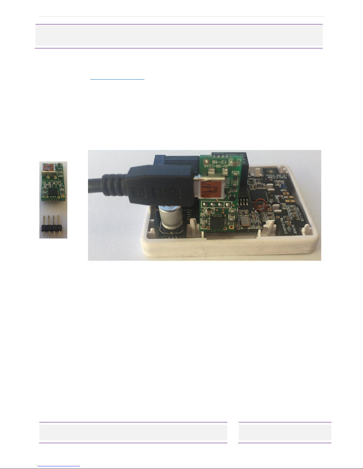
When operating normally, D3 (visible with case removed) will flash green once every second.
When the relay is in the closed state the red LED D1 will be lit. The relay will operate only when a
correct Salcom relay control message is received with a matching unit ID.
There is no visible indication when either of the two open collector outputs are operated,
making them well suited for extremely low current applications. When only open collector
output control is required the 12-88 can be supplied with any voltage down to 4 volts. A 12 volt
supply is required for relay operation.
To control the outputs a message must be received that matches the unit ID with a suitable
control code sequence (Salcom relay control protocol). The received message must also be
the expected baud rate (512 or 1200) and format (alphanumeric or numeric). The 12-88 will
also respond to a group unit ID of “00”. The onboard relay is addressed as output 1, open
collector outputs as output 2 and output 3.
A mono-shot timer can be set for each output allowing the output to open automatically after
being closed. This mono-shot timer can be set to between 100mS seconds to 100 minutes (in
100ms steps).
Setting any output mono-shot timer to 0000 results in the output remaining latched until a
message is received to change its current state.
If configured to do so, each output state will be stored and restored to the last set state on
power up.
The 12-88 can be configured to respond to up to 4 different cap codes. Setting any cap code
to 0000001 will result in all cap code messages being examined for the output control message.
Unit Number
Each unit will respond only to messages containing a matching unit ID or a group ID of 00. Up to
99 unique unit numbers are available when configured as a numeric receiver (00-99).
Approximately 8000 unique unit codes are available when used as an alphanumeric receiver
(any 2 printable characters).
Any number of units can be programmed with the same unit number.
Mono-Shot
Output mono-shot (momentary) operation can be enabled if required. Each output can have
its own Mono-shot time, ranging from 100mS to 100 minutes in 100mS steps. Setting the value to
0000 disables the mono-shot timer altogether, and the relay output is latched until
commanded off.
If the unit is configured to restore output states on power on, output state restoration will not be
applied to any output with a configured mono-shot time set.

P a g e | 6
12-88-7000 OUTPUT CONTROL RECEIVER
Product Manual
Sea Air and land Communications Ltd, 10 Vanadium Place, Addington, Christchurch 8024, New Zealand July 2017
Output Control
Outputs are controlled using Salcom relay control protocol. The control message must be at the
start of the paging message in order to be processed. Outputs 2 and 3 are treated as relays in
the examples below for clarity.
Control commands take the form UUxxx0yyy9 where:
UU is the 2 character unit ID
xxx = outputs to close, combinations of 1(relay), 2,3(open collector).
0 marks the end of outputs to close.
yyy = outputs to open, combinations of 1(relay), 2,3(open collector).
9 marks the end of the relay command data.
A red LED will display on the PCB showing when the relay is closed, but there is no indication
when open collector outputs 2 or 3 operate.
e.g.
23109 Will only address a unit with matching ID 23. Relay 1 will be closed. No other
action taken.
23019 Will only address a unit with matching ID 23. Relay 1 will be opened. No other
action taken.
231209 Will close relay 1 and 2 on a unit with the ID of 23.
230129 Will open relay 1 and 2 on a unit with the ID of 23.
2301239 Will open relay 1,2 & 3 on a unit with the ID of 23.
231029 Will close relay 1 and open relay 2 on a unit with the ID of 23.

P a g e | 7
12-88-7000 OUTPUT CONTROL RECEIVER
Product Manual
Sea Air and land Communications Ltd, 10 Vanadium Place, Addington, Christchurch 8024, New Zealand July 2017
Configuration
In order to program the12-88-7000, programming software should be downloaded from the
Salcom website (www.salcom.com). Alternatively, a suitable terminal program can be used to
program the 12-88-7000.
To connect the programming computer to the 12-88-7000 either use a
•12-47 serial programming interface or
•12-48 USB programming adaptor with a micro USB to USB cable (not supplied)
These should be connected to the 4-pin programming header, as shown below.
Connecting the 12.48 USB programming adaptor to the 12-88
Note: Remove the header plug, as shown on the left-hand picture
If using the 12-47 programming cable and a terminal program ensure the Serial RS232 RTS
(Ready To Send) control line is set to active. The RTS line provides the DC supply to the 12-47
RS232 components inside the D9 cover.

P a g e | 8
12-88-7000 OUTPUT CONTROL RECEIVER
Product Manual
Sea Air and land Communications Ltd, 10 Vanadium Place, Addington, Christchurch 8024, New Zealand July 2017
Configuration Commands
All serial commands are sent and received using a standard terminal application connected at
9600:N:8:1 using a 12-47 or 12-48 USB programming adaptor.
When the unit is first powered the sign on message and configuration options will be sent from
the 12-88:
Salcom 12-88-7000 V1.2
+01 ID: 01
+02 Freq: 458600000
+03 RX Mode: A512
+05 RIC 1: 1233333
+06 RIC 2: 0000001
+07 RIC 3: 0000000
+08 RIC 4: 0000000
+21 O/P MS 1: 00100
+22 O/P MS 2: 00000
+23 O/P MS 3: 00000
+30 O/P Restore: 0
ID: The unit ID is used to uniquely address a unit to control outputs. The unit ID must be 2
characters. If numeric decoding is specified, then the unit ID must be between 00 and 99. If
alphanumeric decoding is used then any printable character can be used as part of the unit ID
allowing for approximately 8000 possible addressing codes. The unit of ‘00’ can also be set, but
is also used as a group address code.
Typical usage: +01= 01<CR>
Freq: This is the receive frequency. This parameter should be programmed to be between
100000000 and 479000000 and must be specified in Hz.
Typical usage: +02=458600000<CR>
RIC: Up to 4 receiver codes can be specified. Each parameter should be between 0000008
and 2000000. Setting a code to 0000001 will result in all RICs being decoded.
Typical usage: +05=1234560<CR>
RX Mode: The mode determines the receiver mode of operation. Possible settings are A512,
A1200, N512 or N1200. ‘A’ specifies alphanumeric operation. ‘N’ specifies numeric operation.
512 and 1200 specifies the receiver decode baud rate.
Typical usage: +03=A512<CR>

P a g e | 9
12-88-7000 OUTPUT CONTROL RECEIVER
Product Manual
Sea Air and land Communications Ltd, 10 Vanadium Place, Addington, Christchurch 8024, New Zealand July 2017
O/P MS (Output Monoshot): If specified, the mono-shot will open the relay after the relay has
been closed for the configured monoshot period. Setting the relay to 0 results in latched
operation (mono-shot timer not operating). The timer can be set in 0.1 second increments from
0-65535 (max 1.8 hours).
Typical usage: +21=100<CR>
O/P Restore: If set to 1, then all outputs that are not configured for monoshot operation will be
saved so that when the power is cycled the output will return to that state.

P a g e | 10
12-88-7000 OUTPUT CONTROL RECEIVER
Product Manual
Sea Air and land Communications Ltd, 10 Vanadium Place, Addington, Christchurch 8024, New Zealand July 2017
Technical Specification
Power Supply
+10 V to 17 V nom 12 V
If relay operation is not required 4-17V can be used
RF Frequency
VHF: 148-165MHz (Model No. 12-88-7150)
UHF: 440-470MHz (Model No. 12-88-7450)
Receive Bandwidth
6.25KHz (minimum)
Frequency selection method
Synthesized, user selectable
Current Drain
Receive average 25mA plus 18mA when relay energised.
Receive Baud Rates
512 or 1200 baud
Paging Protocol
POCSAG
Receiver Sensitivity
Approx -124 dBm
Serial input/output
9600 baud no parity, 8 data bits, 1 stop bit
for changing unit parameters)
Outputs
One relay and two open collector
Relay Contacts
1Amp @24VDC (Not suitable for 240VAC connection)
Open Collector Max Current
Outputs 2 and 3 can sink up to 80mA each.
Aerial Connection
Internal PCB, or external SMA as required.
Operating Temperature
-10 to +50degC
Enclosure
Dimensions: 66mm x 50mm x 26mm (with mounting holes).
Material: Plastic
Environmental Protection
Indoor use only

P a g e | 11
12-88-7000 OUTPUT CONTROL RECEIVER
Product Manual
Sea Air and land Communications Ltd, 10 Vanadium Place, Addington, Christchurch 8024, New Zealand July 2017
How to Contact Us
Sea Air and Land Communications (Salcom) Ltd
10 Vanadium Place
Addington
Christchurch 8024
New Zealand
T: +64 (0)3 379 2298
W: www.salcom.com
Table of contents
Other Salcom Receiver manuals