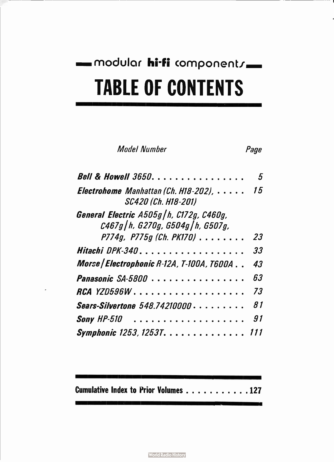
Sams MHF-37 User manual

Bell &
Howell
3650
Electrohome
Manhattan,
SC420
General
Electric
Cb.
PK170
Hitachi
DPK-340
Morse
I
Eleetrophonic
R-
12A,
T-
100A,
T600A
Panasonic
SA-
5800 —
RCA
YZ0596W
Sears-Silvertone
548.742717000 —
Sony
HP-510
Symphonic
1253,1253T


$3.95
$4.95
IN
CANADA
Cat.
No.
MHF-37
f
OM'
modular
1
1rl
. i
component;
MHF-37
REPRODUCED
THROUGH
THE
COURTESY
OF
THE
MANUFACTURER
çdL
HOWARD
W.
SAMS
lit
CO.,
INC.
INDIANAPOLIS,
INDIANA

First
Edition
First
Printing—
May,
1973
Copyright
C)
1973
by
Howard
W.
Sams &
Co.,
Inc.
Indianapolis,
Indiana
46206.
Printed
in
the
United
States
of
America
All
rights
reserved.
Reproduction
or
use,
without
express
permission,
of
editorial
or
pictorial
content,
in
any
manner,
is
prohibited.
No
patent
lia-
bility
is
assumed
with
respect
to
the use of the
information
contained
herein.
Library
of
Congress
Catalog
Card
Number
72-77606

...modular
hi-
In
component/
TABLE
OF
CONTENTS
Model
Number
Page
Bell &
Howell
3650
5
Electrohome
Manhattan (
Ch.
H18-202),
15
SC420 (
Ch.
H18-201)
General
Electric
A505g1h,
C172g,
C460g,
C467g
I
h,
8270g,
6504g/h,
8507g,
P774g,
P775g (
Ch.
P1(170)
23
Hitachi
DPK-340
33
Moire
I
Electrophonic
R-
12A,
T-
100A,
T60011 .
43
Panasonic
SA-
5800
63
RCA
YZD596W
73
Sears-Silvertone
548.74210000
81
Sony
HP-
510
91
Symphonic
1253,
1253T
111
Cumulative
Index
to
Prior
Volumes
127

GENERAL
SERVICING
INFORMATION
The
following
information
applies to
all
players
in
this
volume,
and
should be
followed
before
any
adjustments
are
made
or
trouble
diagnosis
is
attempted.
Any
exceptions
or
additions
will
be
found
in
the
detailed
servicing
procedures
for
each
player.
POWER
SOURCES
Many
players
require
full
supply
voltage
for
proper
operation.
Be
sure
the
supply
voltage
is
maintained
at
the
rated
value
under
load
while
making
adjustments.
CLEANING
Head
faces
should
be
cleaned
with
head
cleaner
to
remove
dust
and
accumulated
oxide. (
An
applicator
may
be
fashioned
from
absorbent
cotton.)
Do
not
use
a screw-
driver
or
any
metallic
object
near
the
head
faces.
CAUTION:
Avoid
getting
head
cleaner
on
any
plastic
surface.
Clean
capstans,
pressure
rollers,
and
tape
guides
with
alcohol
using a
soft
lint-
free
cloth.
Also
use
alcohol
to
remove
oil
and
grease
from
drive
belts
and
other
driving
surfaces.
LUBRICATING
Clean
all
surfaces
before
lubricating.
Apply
a
few
drops
of #
20
machine
oil
to
all
bearings
and
rotating
bushings.
Apply
a
thin
film
of
light,
nonhardening
grease
to
all
cam
surfaces
and
pawls,
if
they
have
been
factory
lubricated.
Always
wipe
excess
oil
or
grease
from
parts
that
have
been
lubricated.
CAUTION:
Oil
and
grease
must
be
kept
off
all
driving
surfaces
as
well
as
any
parts
which
may
transfer
oil
or
grease
to
them.
DEMAGNETIZING
Heads
require
demagnetizing
at
regular
intervals
to
maintain
high-
frequency
response,
dynamic
range,
and
low
distortion. (
Follow
instructions
included
with
the
demag-
netizing
unit.)
After
demagnetizing
the
heads,
keep
all
screwdrivers
and
other
metallic
objects
away
from
the
head
faces.
Tape
guides
may
also
require
occasional
demag-
netizing.
IMPORTANT:
Be
sure
to
demagnetize
the
heads
after
making
resistance
measurements
in
the
head
circuits.
CARTRIDGES
Many
problems
associated
with
tape
players
result
from
defective
cartridges.
Always
try
a
cartridge
known
to
be
good
before
attempting
repairs.
4

.4.10MI
modular
component/
Pages
5-14
Courtesy
of
BELL &
HOWELL
GENERAL
SERVICE
DEPARTMENT
Bell &
Howell
3650
ALIGNMENT
INSTRUCTION
Circuit
adjustment
The
instructions
for
adjusting
the
FM
and
AM
circuits
will
be
given
in
this
section.
1.
FM
Circuit
1-1.
Test
Equipment
Required :
FM
band
signal
generator :
400
Hz
30%
modulation (
22.5
KHz
deviation) ;
300
ohm
Output.
FM
IF
sweep
generator:
10.7
MHz ±
500KHz
VTVM:
Low
range
AF
Oscilloscope :
High
sensitivity
general
purpose.
Accurate
audio
generator (
SCA
signal
generator
7
KHz
dey.)
FM
stereo
signal
generator :
For
MPX
tests.
1-2.
IF
Amplifier
Alignment :
Note:
a.
For
safety,
the
output
should
be
connected
to
the
loudspeaker
or
equivalent
resistance
loads.
b.
Set
the
panel
controls
as
follows:
FUNCTION
selector
to
FM
VOLUME
control
at
minimum
output.
FM
AFC
switch
to
OFF.
V
curve
c.
The
output
of
IF
sweep
generator
should
be
connected
to
Test
Point
A (
the
connecting
point
of
R106,
220
ohm
and
C109
2pF).
d.
The
input
of
IF
sweep
generator
should
be
connected
to
Test
Point
B (
Q9
2
SC460
collector).
S
curve
e.
The
input
of
IF
sweep
generator
should
be
removed
from
Test
Point
B (
Q9
2
SC460
collector)
and
be
connected
to
Test
Point
C (
R336
15k
ohm).
f.
The
probe
for
input
or
output
of
IF
sweep
generator
should
be
connected
as
Fig.
1.
22Kn
0.04p
F
OUT
0—A,VW—I
PUT
For
OUTPUT
o
2PF
INPUT
0
22KC2
0.5p
F
o
44
1)
1.
0.01p
1
N60
mum
100KC2
For
INPUT
ci
For
INPUT (
S
curve)
/,
5

STEP
ADJUST
WAVEFORM
1
T,
T2,
T5, T9,
T11, T13,
(Primary)
Best
V
Curve
2
T13 (
Secondary)
Best
S
Curve
1-3.
FM
Tuner
Pack
The
FM
tuner
may
require
adjustments
when
the
signal
is
distorted
or
when
the
sensitivity
has
been
lowered.
Set
the
FUNCTION
selector
to
FM
and
the
FM
AFC
switch
to
OFF.
In
the
steps
to
follow,
the
FM
signal
generator
is
set
for
at
30%
modulation
at
400
Hz
at
the
RF
output
freque-
ncies.
For
the
output
indication,
the
VTVM
and
the
scope
in
parallel
are
connected
to
the
Right
speaker
outjack.
Step
1.
Set
the
generator
output
to
87
MHz
and
tune
the
receiver
to
this
signal.
Adjust
the
trimmer
FCT3
and
Coil
L5
for
maximum
output.
Step
2.
Set
the
generator
output
to
108.5
MHz
and
tune
the
receiver
to
this
signal.
Adjust
the
trimmer
FCT2
and
Coil
L3
for
maximum
output.
Step
3.
Set
the
generator
output
to
98
MHz
and
tune
the
receiver
to
this
signal.
Adjust
the
trimmer
FCT1
for
maximum
output.
Step
4.
Repeat
the
adjustment
of
Steps
1,
2,
and
3.
Note:
In
the
above
adjustments,
do
not
forget
to
keep
the
generator
output
level
as
low
as
possible
for the
best
results.
DIAL
STRINGING
Small
Pulley
4pcs
Large
Pulley
Tuning
shaft
6

o
C
511
001
560
4..„
„T
s4
C432
002
1
0
.(_.)..
Y
.-
C420
*1
5
1K
C430
as *
---
4
@)ots \
141
1
1A
I
22
•
p
442
too»
288187
/
83
e
C431
17
1D
1
,,
, 41
09
220
443
OK
33K
e444.10-1-«
e445
31
à /
25
,
041
04;
W
220K
SEA
4--
eR6C5
5840
tO
fl
416
6.68
Rtin
*-4
5
.-
677
,
Q
frbl
e
22
1
I
/tw
C;10
.28
473%‘
5,
C506
C505
•-•<C>-•
001
001
\
68
560 , •
to
e•
4135
•
7
-
ee9"
TH2
C416
122
&)=
4
V:
IA
—
C
4i
100
r
4"0
1
4-
4
•-
.C>••
TH
t
0- IA
05
C405
1(,
,
/
25vc406
841
,1
2w
1
451.
K410 ,
'2A
I
5.
c4
04
1•
6.5,,
_
33
r00
1(
e02ii40:02
3•ej
,2881
g
.
2004K0‘
00
,
-
125,
-
-0*
C404
130K
8484
cli
e
).
4
-2:
40(
6E4010
0 ,
5
m216
0
47/
l
e
K
16,/
C403
le,
25 •
Od
Alddr1S
kl3M0d
ea
o
ClkIVOEI
Od
oicinv
029C
nomoll
e
¡
too

PARTS
LOCATION
OF
TUNER
PC
BOARD
r2r
39Ø
1M
e
PARTS
LOCATION
OF
IF
PC
BOARD
C12110
100P
C230
e<I>+
004
3
162
o
•
WM-
1403
•
227
IN
'
S4.
7K
!8C460
II
004
C'226
OOP
K
•-2-2
K
C22
-
0
OIM
•••••
600
1
4
C222
S
OK
4
PK
C219
Qom
<D.
•—€)
I5K
t.
•
•
1'
12
R2.5
R237
•
680
8.18C
C-24.
C231 ?
OK
eg
z
C2I3
/l
ey
1
10 .
•
-
15•
CM "
4
T7
61°
T
.
A-18.
C207
op,
(70:—.
e.
C206
flfl
R22t
4
7
0.04
eC
k'
IN60
o
Ram
C201
e•
C59016
1F,G)
.2.
5K
T6 *•
I
5K
3..5K
A-16.
Fè
)_
2
fl
C208
0.04
R
208 .
1(
8

Note;
Resistors
with
dark
markings
are
low
noise
types.
PARTS
LOCATION
OF
MPX
PC
BOARD
c3o1
301
OOK
R302
80
L2
F21
CIOI
20P
Fc
TI
C127
03
sEsoo6
Q.
SE
3001
22
/6
.3
C
329
OW
--
c73
-
31 ,
20
47
ti
0,
9
SE
100
I
/103
470K
R336
i5K
r,4
ns
R337
33K
01
•
C3o3
c3o5
R304
10000
T
i000pg306
e
C3047•
33K
50oP
0.01
Q,,
5E5050
C102
SOP
100
éP
R113
8.2K
3
'cri
Alos
2.2K
04.SE5006
R
130
K
RI31
C70
680P
Rot
too
1ANW.
R/06
120
33
4
II
cue
220
es,$E
300
I
12123
Acré
RI12
2.2K
0,,
SE /
001
R305
CI03
8.02
VI*
R12•
56
Cie/
r°
6
0,2
SE
1001
De,
be (26
3
SE /
00!
14160.2
Cie
T,
6
T/9
seJoP
C21/
InoP
5314
1.50K
R308
2.2K
R309
15K
FM
LCIC
FM_
Red
1-57(
R31.5
.56K
R312 5313
51.0
OK
ne
2200P
R318
ior(
COOS
C308
30/
4
2334-
3
34
6
330
FM
STEREO
PNO_NO
AM
rA
PE
0
Puy
AIOTES
I)
sELECTOR .
5I'/ITCH
IS
SHOWN
IN
All
POSITION.
2)
ALL
RESISTANCE
VALUES
ARE
INDICATED
IN
OHM (
K=
WORN,
14 =
10%11)
3)
ALL
cAPACITAAKE
VALUES
ARE
INDICATED
IN ,
I.LF.(P-10
-6
,
11
F)
T
19
,, ,
rSvo.
,
,,
.!:
SE3tial
ç,',
,
,
330
"114
,
1
1-
i
r
Ir
.)
Í
.-
c
30
7
-
r,
p
,2_1_
,
i
R
701
33
5 .
2j1
,
1 :
I
1
R
.,,,
0,3< i Item
-
1
3'01
1/-"
Ce
li
.:1
4
0„
e
•L ;:
06
¡TIM
1
0.04
FT
RIGHT
D„ .
Da,
D,
i
,
Dm.
IPI60.
4.
324.
Qc33206,
er
oconTo
:
4.
31
70k
33K
3
3k
R
six
_ 1 11
-1
:
0K
..-•-
il
130
,
130,
R341
Jr,
le
‘ ''
rer
C331
0
47
12325' '
yin
Z
.30,
324,
2
.5
70
x
Ci21
J3
K
e
gh
56
‘e
c.333
1:04:
ROO,
1M
'322
3o
4
,
30
1 '
of
I
R3
38
R332 _
11
2
11
sr
INDICATOR
.00K
470
it?
035
3
k
l
Cs36
25
0e
5339
i.51(
C.21
1
I
RV7
oto
se210
12
C207
0.04
208
1/(
I
C?
"
0.04
PHOI
Ti
PE
,
N
I .•
330
Re7
C321
22K
3.34
R.,
5
C32
6.8K
TAPE
OUT
02/0
10..
4
R209
,
SOK
Cool
40P
410
0/4.
CS
901
Z
C316
34/
4
le
pL
2
.
P&
L
PLa
OUTLET
34
7
Fee
/A
R503
2214
Dd
Ch. /
0D
-
I .
2
5502
R.501.
220
ea,
H
De /
00-
-
RSiO
I
2A1
R501
INVER
Sty
" 1
-r
CS1/
2.2.1
RSoS
R506
220
2
20
C.592
490z
/Z5
C513
1-
C601.40?
1
-1
W.
1.
1-
1
CS74
C
33o
/00/
i
,
1
27,
CS./J.
41
-
sE
3001
R213
$
60
Iv
De.
0
4
11460.2
IC213
R604
4.1g
Qe
C.5(10/6
or
583001
12216
560
C214
0.02
I •
t
211
e
404
8237
6.91(
R601
471(
11606
eV<
by
rO,
C116
nod
2,
7
402
MV-
3
or
Flit-
23
C216
04
25
460
R239. ix
R218
2.2K
C231
/0
//6
Dé,
13160,
Re
5220 c2/7
iS
0.01
2238
47K
Cz22
0./
C2
12-
I
441
C2202-
R223
0.04
/501(
SE40/0 (
2,7
SE4010
C403
R408
inx
Mh
R439
R407
10K
43
.K
C404*
""
4/4
6.5
..e
c
K
og
-
W61
-6
•
R4I3
.33K
mog •-;
0405
R4I2
405
10/
25
.51K
C40,
820
P
LO
MONO
-0
MODE
s
rEREO
C417
m7
4
a
l
SS
Y
R439
2zeh.
R340
220
R438
33K
5440
100K
1
%5
-
5443
220
4446
IOK
(4,21
°
P25
Q/.2
ZSB
/
86
C410
20,
12
1
-51
42I
3.3K
2420
220K
C409
554
6
C425
3.3/,
R450
OK
2
C
•23
5.i(
820
k
-oaà
R43I
C42t
3K
0.,
5433
1
.SK
0452
560
I/
18160 •
2
R234
R235
23
C227
/00P /
0g
R2
30,/1C
RTz7
47
5228
47
C221
tooP
1
Q224
680
P413
51e
R47,
2K
£454
82x
68
2,.
2se
/
87
2428
220
C228
2224
1
c
230
Q,
Q24
258
474.2
I242.1
7;7
I
680
430
R43,
0.5
002
5432
f
oo
VWV.
R436
560
025.
Q16
C415
C4,6
002
R449
60
255474,1
R401
680
•
246S
744
22
-
2466
500
FUSE
0.754
R403
0.3
-
47ol
e
41... •
C43i
C43I
SAID
002
RI
Fr
Hr
9
10
11

1-4.
FM
Multiplex
Circuit
a.
Test
Equipment
required
SCA
signal
generator :
MPX
signal
generator:
FM
signal
generator:
VTVM:
Low
Range
AF
Dummy
load
selector : (
With
L
ch,
R
ch,
exchange
switch
and
8
ohm
Resistor
built-in)
Refer
to
Fig.2.
Exchange
Switch
INPUT
L
ch
INPUT
R
ch
F
ig.
3
67KHz
output
0.5V
Dev
7KHz
Modulation
1KHz
or 400
Hz
Modulation
1KHz
Deviation
L
33.7KHz
Dev. (
45%)
R
33.7KHz
Dey.
(
45%)
Pilot
signal
7.5KHz
Dev. (
10%)
Frequencies
98MHz
Deviation
75KHz (
100%)
T-
-
Dummy
Load
Selector
Oscilloscope :
High
sensitivity
general
purpose
b.
SCA
Circuit
Adjustments
Step
1.
SCA
SG
output
are
connected
to
C301 (
3uF/16V)
and
VTVM &
8
ohm
resistor
are
conne-
cted
to
the
jack
of
right
speaker
in
parallel.
Step
2.
FUNCTION
selector
is
set
to
FM
Stereo
position.
Step
3.
Adjust
the
transformers
T14
and
T15
to
maximum
audio
output
power
shown
by
SCA
signal.
c.
STEREO
Circuit
Adjustments
Step
1.
The
output
of
FM
signal
generator
is
connected
to
the
ANTENNA
terminal (
300
ohm)
of
the
set.
Step
2.
The
modulation
of
Stereo
signal
generator
is
changed
to'R
-
ch
signal
.
by
following
methods.
a.
Turn
the
Dummy
load
selector
toIrch
b.
FUNCTION
selector
is
set
to
FM
position
Step
3.
The
output
of
FM
signal
generator
should
be
turned
to
98
MHz,
30/4V
accurately.
Step
4.
Set
the
FUNCTION
selector
to
FM STEREO
position.
Step
5.
Connect
the
VTVM
to
transformer
T18 (
secondary).
Adjust
the
transformers
T16,
T17
and
T18
for
maximum
output.
Step
6.
Connect
the
VTVM
to
right
speaker
and
adjust
the
transformer
T18
for
maximum
output.
Bell &
Howell
3650
d.
SEPARATION
Adjustments
Step
1.
Set
the
output
of
FM
signal
generator
to
60
dB (
linV)
Step
2.
Set
-
Reh
volume
control
R450
to
the
position
of
2V (
8
dB)
Step
3.
Turn
the
stereo
signal
generator
from
-
Reh
to
-
Leh
and
bring
down
the
dummy
load
selector
switch
to"Reh.
Step
4.
Set
-
reh
volume
control
R415
to
the
output
position
of
2 \"' (
8d1i)
Step
5.
Turn
the
dummy
load
selector
switch
to
-
R
eh
side
without
changing
the
modulation
of
stereo
signal
generator,
and
then
adjust
the
volume
control
R318
for
-
Reh
output
less
than
18dB.
Step
6.
Change
the
modulation
of
Stereo
signal
generator
by
-
Reh
and
switch
on
dummy
load
selector
to
-
Leh.
and
then
confirm
to
be
less
than
18db
for
-
Leh
audio
output.
e.
Check
of
Stereo
indicator
lamp
Check
the
Stereo
indicator
lamp
whether
it
is
illuminated
or
not
when
the
stereo
signal
of
the
outputs (
26db)
is
received
from
FM
signal
generator.
AM
Circuit
Test
Equipment
Required
AM
standard
signal
generator
covering
the
455
KHz
IF
band
the
medium
wave
band.
The
modulation
is
set
to
30%
for
400
Hz
modulation
frequency. (
If
available,
a
sweep
generator
for
the
455
KHz
band
will
speed
up
the
alignment.)
VTVM :
Low
range
AI;
Oscilloscope :
General purpose
IF
Amplifier alignment
Note :
a.
For
safety,
the
output should
be
connected
to
loud
speakers
or
equivalent
resistance
loads.
b.
Set
the
panel
controls
as
follows :
FUNCTION
selector
to
AM
MODE
selector
to
MONO
VOLUME
control
at
fully
clockwise (
maximum)
c.
The
at a
Step
1.
Step
2.
Step
3.
Step
4.
Step
5.
modulated
455KHz
signal
is
connected
to
transistor
Q4 (
SE3001)
Base,
and
should
be kept
low
level
consistent
with
good
measurement.
Connect
the
VTVM
to
the
Right
speaker
terminal.
Connect
the
resistor
100K
ohm
to
the
transformer
T7 (
secondary).
Adjust
the
IF
transformer
T6,
17,
Tb,
and
T12
for
maximum
indication.
Repeat
the
step
3
two
or
three
times.
Disconnect
the
resistor
100k
ohm
from
the
transformer
T7 (
secondary).
AM
Tuning
circuit
The
panel
control
setting
is
the
same
as
for
IF
amplifier
tests.
The
VTVM (
and
scope)
connection
is
made
to
the
right
speaker
terminal.
The
signal
generator
is
set
to
30%
modulation
of
400
Hz
output.
Step
1.
Set
the
generator
to
600KHz
and
connect
to
loop
antenna.
Tune
the
receiver
to this
signal.
Step
2.
Adjust
the
oscillator
coil
T4
and
the
shorting
ring
on
the
antenna
loopstick
L6
for
maximum
output.
Step
3.
Set
the
generator
to
1,400KHz
and
tune
the
receiver
to
this
signal.
Step
4.
Adjust
the
trimmers
ACT1,
and
ACT2
for
maximum
output.
Step
5.
Repeat
the
steps
1
through
4
two
or
three times
for the
best
tracking.
NOTE:
WHEN
ORDERING
PARTS
NOT
OTHERWISE
LISTED,
ORDER
FROM
MANUFACTURER
BY
ITEM
NUMBER
AND
DESCRIPTION.
SEMICONDUCTORS
ITEM
PART
NO./TYPE
D1
1S21398
D3
1N60
D4
1N60
D5
HV-23
D6
1N60
D7
1N60(P)
D8
1N60(P)
D9
1N60(P)
Q1
0
1N60(P)
Dl]
1N60
P )
D12
1N60(P)
013
1N60(P
D14
1N60 (
P )
D15
10D-1
D16
100
-
1
D16
10D-1
017
100-1
D19
10D-1
D20
10D-1
Q1
5E5050
Q2
SE5006
Q3
SE5006
Q4
Q5
Q6
Q7
Q8
Q9
Q10
Q11
Q12
Q13
Q14
Q15
Q16
Q17
Q18
Q19
Q20
Q21
Q22
Q23
Q24
Q25
Q26
5E3001
SE3001
CS9016
CS9016
CS
9016
2SC460
SE1001
SE1001
S El
001
SE1001
CS9012
SE4010
SE4010
SE4010
SE4010
2SB187
2SB187
2SB186
2SB186
2SB474
2SB474
2SB474
2SB474
ELECTROLYTIC/VARIABLE
CAPS
ITEM
VALUE
AC]
AC2
AC3
ACT1
ACT2
C116
C129
C213
C228
C231
C301
C302
C308
C309
C313
C326
C330
C402
C403
C404
C405
C406
C409
C410
C411
C412
C414
C415
C417
C425
C427
C428
C430
C431
C501
C504
C508
C510
C512
C513
C514
AM
Tuning
Gang
AM Antenna
Trimmer
AM
Oscillator
Trimmer
33mfd
16V
22mfd
6.3V
lOmfd
16V
lOmfd
16V
lOmfd
33mfd
33mfd
3.3mfd
33mfd
3.3mfd
3.3mfd
100red
.47mfd
lOmfd
lOmfd
lOmfd
lOmfd
3.3mfd
220mfd
100mfd
3.3mfd
100mfd
470mfd
.
47mfd
3.3mfd
100mfd
3.3mfd
100mfd
470mfd
100mfd
500mfd
1000mfd
470mfd
470mfd
470mfd
470mfd
16V
16V
16V
16V
16V
16V
1.6V
16V
16V
25V
25V
25V
25V
16V
25V
6.3V
16V
6.3V
25V
16V
16V
6V
16V
6V
25V
50V
50V
Dual
50V
25V
25V
25V
25V
FC1
FC2 FM
Tuning
Gang
FC3
FCT1
FCT2
FCT3
FM
RF
Tuner
FM
Antenna
Trimmer
FM
Oscillator
Trimmer
CONTROLS/S
PEG
I
AL
RES
I
STORS
ITEM
PART
NO.
DESCRIPTION
R318
R382002
10K
Separation
R335
6.8 ohm
R431 .
5
ohm
WW
R434 .
5
ohm
WW
R463 .
5
ohm
WW
R467 .
5
ohm WW
R471
R382009
2000
ohms
Gain
R472
R361033
100K
Balance
TH1 D-
1A
Thermistor
TH2
D-
1A
Thermistor
TH3
D-
1A
Thermistor
TH4
D-
1A
Thermistor
COI
LS/TRANSFORMERS
ITEM
PART
NO.
Il
12
T3
14
T5
16
T7
T9
110
T11
K-112
K-113
RM018
0M0163
WM1401
A-16
A-18
WM1401
B-15
WM1402
T12
C-24
T13
WM1403
T14
H801
T15
H801
T16
H802
117
R120049
R18
H804
R19
H803
120
R1
20049
T21
R110080
MISCELLANEOUS
NAME
PART
NO.
Fuse,
IA
Fuse, .
7A
P.C.
Board,
RF
P.C.
Board,
IF
P.C.
Board,
MPX
P.C.
Board,
Audio
Switch,
Selector
Switch,
Power
Switch,
Mode
Switch,
Loudness
CABINET
PARTS
NAME
R412009
R412010
R530188A
R530189B
R530191B
R5301 92B
R421023
R429025
R429024
R429024
PART
NO.
Board,
Side
R849027
Cover, Top
R651396
Cover,
Bottom
R651169
Panel,
Rear
R651383
Plate,
Control R636491
Plate,
Decoration
R636492
Trim,Escutcheon
R810900
Knob,
Selector
R871129
Knob,
Tuning
R871128
Assembly,
Speaker
Cabinet
R849028
12
13
14

fa
mi
moduler
hi-fi
component/
Pages
15-22
Courtesy
of
ELECTROHOME
LIMITED
CHASSIS
LAYOUT
T
UNE
R
BOARD
( (
aggro
,
*
er )
TB
TA
3.
0508
0607
0608
:
•
(1)
'is
[
•
•
•
se
3.
32
c
e
j
AUDIO
AMP.
BOARD
seE
AAEAS
L
-1
',S..
5,
5
2
STRINGING
DETAIL
LEFT
CNANNE
iCesT
CHANNEL
TREBLE
FNONO
J_5.0
gt
Electrohome Manhattan
(Ch.
H18-202),
SC420
(Ch.
H18-201)
epee
7
ReiLF_IRK40
r
401
%YE
,:
je.
ISO.
r •
CW
I ;
20!
FUNCT
ION
SW
0
SWIAB
C D
E
PSI
a.
AA
FA
F1AS
• °
T
S3
15

4
0 •
c
522
•
44
(1
48
C622
()).
4
1
-•
R531
B/Q504
c •
Orm
E
R631
B,,0604
C
f›Uib
E
C
62
5
C
52
4
C62
4
•C>
R530
6-1
1--•
•-f
t---•
R
533
R536
R
63
6*
--
L—i
-40
•-f
---
i--.•
C
52
5 •
C
627
I
r.....
9
R
cc
•
re)
in
Li
--
• _.
R
6
30
1---•
R633
•
B •
37
E •
38
cc)
3
9 •
C
R 6
41
R635
3
4 •
B
e
R638
ti)
cr
R
6
39 ^
o
o
4
3
• - + •
R532
C
527
cr
5
e
—•
•
8
L
R
5
4
I
R535
t
0
505
C•O•
E
1
0 •
B
,c
, •-
L_____1-•
e
R538
I i
•
E
in
x
e-
L_.1--•
R
5
39
i's•
8 1 31
o
E •
32
to
o
(e)
3
65
C
3
3 •
C
TRANSISTOR
VOLTAGES
PHONO
FUNCTION
NO
SIGNAL
LEFT
Q
RIGHT
sa
B
E
C
504
604
-18.0
-17.8
-26.6
505
605
-26.6
-27.3
-13.9
507
607
-13.9
-13.8
-27.3
508
608
-13.7
-13.8
0
I
2 •
C
AUDIO
AMPLIFIER
COMPONENT
LAYOUT
16

FM
-
RF
LI
121
-11.9v
114-70 0
1
S
D
V
,r
zsu
c,
-
12.4Y
In C
10-
CT
120
_
1.2
FFI
RF
TOi
FM-
MIX
AM-
FM-
IF
06
02
(14-603-10)
.(y
(4-603-02)
PST
PM
Fr
I
-
2438
10.2
0
e
6
il
4
.Z"._
r-
-
-
1
-toad
1
i
ee
Ke-c
2.2n >
RI)
10
.
%
'
37..311
23F
re
Lau
2110
Fit
If
I
6
T
_1
I!CEO
11
2
/11
1
2
T
10%
I
I
- _
C12
IC2
R2
Fa
n
1.
-
5K
p0
5
;/.
N.C.
('4
ti
-
FTerT4)
Rb
.6
bV
2.711
C
I
3
Sp ¡•
51
,
NP0
FM
OSC.
4814
‘1K
FM
OSC.
03
(IF
-
60'5
-
02)
-5v
V
'VOLT
.
C5 R3
.
C11
-4.sv
1
•••
2.211
/
111p
RIND
'STAB.
:5
,
>
{117
.
4.he
1
77
-
25u
ter-
W
De
sc:
),
1
RI
C14
2.
,
OOK
(10-1)
:53
"
2.2n
10V4
25t
RI?
1121
423
07
6115
er.
(14-603-
02)
3110
Fern
IT
OV
1
6T-.
4
12.0V1
I
c
21
1 _
C24
1000 ,
25F
(23
10%
I
0%1.
25P NIL
I
.
1
_
1
5
1
2
L
¿ND
4.
1
6
-1
ce-
R20
TUNER
P.
C.
BOARD
r - -
ede
e -
610
r2.
1HI
I
10.8V
I
ISM
2?
I8X
le
1119
ei.1
1
ot
28
T
470p
z5O
•
V
C29
2.2"
,
1
10,4
1
_
624
C
32
I_ _ _
5R:
A«
if
79
.
11
le0On
MYL
era
T ? -
DISCRIMINATOR
-
I
AM-
DET
•
FM
-
IF
14
-
OOP
E11.4
(14-514-114
1
3
e
14
30
jeon
-.10
5
/0
mYL
9
7e:
54
Ge
114-514-111
AM
-
MIX
114-51403 !,
I
A....
F(.(
a
T
.-€
io-•
1(I0-ATt.'3
Elm
3-
in •
Et"
IA4
PHONO
AC
SOCKET
J.01
470
Fen
>0
0
Jle1
(
1111
(2
(14 -
603-12)
C55
.5C
AP/.
P
lo-
ST
10-8 ,
C
Er
1:1
101.
C
3
896
F15_
1,
4 N.
L1
37Sm
1K
T
erxTee '
en
10% •
s• -
.
2.6111.
TEL
Oa
r - -
,
4
120V
AC
100W
MAX •
J402
20V
AC
60.4g
1
, I
5
LS
114-914
III
Ah"e
'C
191
AM
I,
T5
•
nc.
meow
e
s
id-
I
,20wER
11403
404
70K
4-
,71;
1600v
POWER
SUPPLY
740,
P401
WHITE
1.0%1
1122
33K
C
SI
1.
25F
3
Re)
1130
tie:Tx
rook
DEF
Ge
14.514-111
I ,
X6
2
7t,
L
34
/2200
FM
'
/
31
Re
iOn
12011
ME.
1128
OK
1131
etia
Teei
fèFS
C36
IM
-
pe
110%
ZSP
(St
1
.16
1004),
R33
011
470K
(
2.?
220ee
1.
0‘
I
r
-
1
1 • ,
.815
Cz1
1152
I
e
•
115
S
ro
4
I
TP7
RIPS
C5
[220..
mYL
AIS
¡ROOK
-
PREAMP
1R
38
220
3 C1
.6
re 57
1
e
r
11.7.
5.
/o
*LIPS
r
_
114-3300-04 )
L
411
..
V
.2
- - -
-9.2y
e
1
1116
-
73,6V
37
220K
r:
To.9
j1140i
300
v2
Y
MIL
C60
T
220,
?ON
o
MX -
DOUBLER
MX
S
IZITCH
R
41
1.8K €
146
38
PH,
L4!
MIL
•
(40
1001-
y
10%
r
-1660
25P
Cs.
SR
A,
85
19Kos,
IE
sm
es.
100n
iRRO
R
39
e
l'
1150
-
K
•
1N0
-
2P.
4
17
1
+
61
44(
3.94
ly
re
Go
p143
-
(e4-
514
II )
80
'59
220p
1.6.1
10
PS
1
R4F
1M
[29.
:43
100P
10%
¿SR
046
.49y
. _
t.by
•1.41
AI
C49
tO0
MIL
1
(4?
31148
2.2x
1220E
10%
25
,
FM
Pi,.
Em
L
EFT
1148
C50
-1.9v
39« '
On
MIL
'CR13
RSC
2.2 -
22CK
10
.
/4
I
10
.
/.
25F 25F
14-
MO-
041
1
GEFEI
0*
25-22-20
"
ANGE
-
27.3v
LEGEND
RESISTORS
UNIT:
OHM (
I% )
1/4
WATT
TOLERANCE
UNLESS
OnmERwiSE
SPEC
oFI(D
CAPACITORS
UNIT ;
FARAD
F )
VOLTAGE
1
1
U OULAR
CURVE()
LINE -
OUTSIDE
FOIL
flECTROLTTIC
CURVED
LINE -
CAN
1
LtRANIC
MICA
OR
OTHER
TYPE
.veT14
NO
00VIOuS
OUTSIDE
OR
GROuNDED
SIDE.
TOLERANCE
AND
TIFIPERATURE
CmARACTENISTK
NOTED
IF
CRITICAL
1
SPECIAL
CAPACITOR
IDENTIFICATION
or
OIL
PILLED
Fi
MICA
SW
SILVER
MICA
PS
POLYSTYRENE
MY ,
RUA/nit)
MYLAP
t4P
NETALi2(1)
PAPER
TEMPERATURE
COEFFICIENT
EXAMPLES:
T.
P
0
NEGATIVE
POSITIVE
¿
ESO
14210
edtGATIvE
ttO
P/31
.
0
TAPE
F
J501
RECORD
26
.1502
PEAT
J602
J50
PHONO
J2113
1.2
IN
1
FUNCTION
SWITCH
I
P.
C.
BOARD
PSOi
1508
_6801
I
1860i
i
leum
I
ISZIK
68K
1
5
lc !
Ir
a
le r
8
I
12 •
9
1
10
6K.
1
0.9
,,
o -11
SPEAKER
SYS
TEM
NO.
1
USED
ON
H -
1
ONLY
SPEAKER
SYSTEM
NO.
I
ROSsOvE
A
NE
TrioRK
I
USED
ON
1118-2
ONLY ;
EXTENSIC•1
„lea
SALERS
.1504
To
SATELLIT
E
SPEAKERS
JEFOR
H18
SCHEMATIC
LEFT
C
SI
I
"100P
Vo
¿SP
C511
530P
Z5P
eC
514
'On
10%
25F
itk4
2711
27x
CL2
lOn
10%
/51
,
Sed
RSI
FILL.
220K
R5i 7
2001
C516
10%
ZSF
C524
;loop
io%
¿Sp
-
pRrAm
-
er -
-
IVER
zu
-T-
Pn
4
R532
47A
8.0v
11595
6.13K
-26
by
115)5
.75J5
(14 -
402-55.
-13.91
-27.1y
050?
LAD,i
0504
_.
,
re
n541
,
-
14-
b02.155)
1
0.51,
-5w
eeiV
-
1.81/
8956
4?
'LUC
6.8K
C
525
100
4
,
25V
11638
678
-
K
T--
11540
'.
526
470
22(4
,,
RY
I.
-13.1v
0508
,
1
0141 ) % -
I3.8v
528
bV
4
0,545
I
5.51/51V1
0.5
0
j
1
r
330
I
/Su
0.01
12
MULTIPLIERS
MULTIPLE
OR
SUR
MULTIPLE
PREFIX
SOME.
i0
6
MEGA
lOT
KILO
10
-3
MILLI
10
-4
MICRO
.
eJ
RA
NO
10
-'2
PICO
í
FALIPLE:
F
10
..
FARAD
▪
.
001
'J
r
«
1000
ott
-
SW1 •
PHONO
SRI
-
VOL
TA;£
NOTATION
DC
VOLTAGES
t
10
.
/0
viITIE
120
ARMS.
bOmz
LINE
_
TUNER
FUNCTION
FRS
SIGNAL
Let/ORBS
1:21:111
A.
nsr
NO
FuLLT
C.Ca.
0.0V
F
m
OFF
NO
FULLY
i
Ca.
F
m
ON
STEREO
FULLY
C
Ca.
-
-
Lue
- -
0.0V
PFICNO
OFF
NO
Fix
,
y
c.,..m.
TRANSFORMER
BASE
S
ST4-41
AIT.'
e
«
F
RE ,
COIJNT UP
LARGEST
IF
e
RAmsropidEas
GAP
eono
.
VIEW
I
Culi
e
C_U
‘L
SE
A0
JIL
I
ANY
NUMBER
OF
LuGS
1
11307TC».
VIEW ;
Iv
I
1
1
1
C613I
R619
,
IlOp
400K
10%
/SP
IC6
,
4
27K
116i4
/SP
10%
IOn
11611
2)%
C612
¿Sp
wir
PRIS
5.4
R
616
220K
EMI
2-20
10%
'SF
1
(622
it)on
41
NIL
II
R6/7
I
200K
Ne
ri
1
1
C616
I
8639
0630
116339
220X
.C624
:6
1.
7n
o
10
.
/4
100P
25F
11631
6210K
(c
:r2
z5
06
04
a
659
I
(1=.140
Rb4I
Le.51 /
Sys
R6.36
47
11637
6.8K
11638
61
-
1W
C
626
c
625
FileL
100
41
•
25V
ow.
11940
470
o.SVO
_
1
0607
e•0162
Z:27 -•
eir5
-
4#
16v
•
RbeIS
Rb43
ryTeee
1
.-
T5w
0.5v.
0608
Fole
10
P.
C.
BOARD
FeLuE
ILL
0.
(.•,28
tn
'su
r--
HE
AOPKONE
JACK
(F•41 ,..r.
FE
14 -
6S2-
46
l.1-
"
Cl
-
55
.4
2GOO -
04
••-6
,
7,2-51
14-602 - :
14
IA -
6(3 -
1,2
II -
60)-
to
TER
TRANSISTOR
LEAD
VIEWS
1
¡
COLL
EC
TOR
the
IT
TER
BASE
14
602 -
RS
GATE
SOuRCE
DRAIN
14 -
700-04
1
COLLECTOR
1
I
EMITTER
5802
AD
162
1
1
1
• 0161
COLLEC
TOR
EMITTER
14 -
603 -
12
17
18
19

TUNER
COMPONENT
LAYOUT
e
•
Ui
•
•
•
•
tg=•=mumil
•
I
a_
•-
1
0
6£
cc
•
•>
•
£e
,
3
1/4
D
Ofrb,
ICI
et
«
(-1
6 £)
•-
I
1-
v.)
•
tf
teI
CC
r•-
TRANSISTOR
VOLTAGES
0
FUN.
01
-t2.4
-11.9 0
FM
02
-10.2
-10.9
0
FM
03
-4.5 -5.0
0
FM
04
-6.6
0
-
FM
05
-9.2 -9.6
-1.0
AM
06
-10.6
-11.4
-2.3
FM
07
-9.3
-10.1
0
FM
08
-4.7 -5.5
0
FM
09
-11.6 -11.6
0
FMS
010
-10.6
-1.6 -1.6
FMS
011
-10.6
-1.6
-1.6
FMS
IC1
-9.2
-10.6
-2.1
FM
09J
•
cilJ
•-
fEila
-
-
LA
ZOLjv
4•
ea
n1
(
cujo
h
F-
jri
•
•
-
-J
rd
91d
l ?)
•"
Z_
O
T
VA
c‘.1
0
.
1
td
1
g_
41.
?)
4
Lur
J4
e.eeee
t
iLe
9?)
6
12i
•eCD: )
b61)
?
„
C1)
>ID
40"
ALIGNMENT
INSTRUCTIONS
ir
to.r.
!Le
gir=;
130/
e
orE2ó.
4
LE:
àfx
u
.
2
g
a
a
E.EE
g
2
m'egg
<
gggé
I- a5
I-
I-
a.
âif
2
I
mle
FM
IF
SWEEP
ALIGNMENT
Electrohome
Manhattan (
Ch.
H18-202),
SC420 (
Ch.
H18-201)
—
SO
OMM
TERMINATION
Scope
to
TP
06
a
g
a
a
y
-
E
Repeat
Steps
6 &
7
until
no
improvement
can
be
made.
MULTIPLEX
ALIGNMENT
.2
E
g
.. I
1
9
I
FM
multiplex
FM
I
FMS
Same
AC
VTVM
T8,
T9
Adjust
for
maximum
1
generator
modulated
Atnenna
to
TP/8
indication.
set
input
level
as
!'
by
19
KHz
pilot.
low
as
possible.
-,
10 '
FM
MPX
gen.
Some
FMS ,
Same
AC
VTVM
T8, 19
KHz
Adiust
for
maximum
indication
modulated
by
MPX
to
Right
Channel
on
right
channel,
minimum
composite
jig !
composite
signal -
indication
on
left
channel.
I
----I—
'
i
right
channel.
1 --
FM
STEREO "
ON
THE
AIR"
ALIGNMENT
là2
à
E
g î
g
É
g <
174
-
e
Trimmers
C10-
0T
CIO-
CT
I
1
,
.
..J
AC
VTVM
TP/5
AC
VTVM
to
TP /
9
1
Listen to
one-
channel
modulation
1
.
r
FAIS
I
Point
of
no
Interference
Te
I:
g
2e...
gm
e
--.
m
-
FM
Ant.
Terminal
-
.
1-.
FM
Antenna
Terminal
r
E
,...
.
E
d
d
C2
re
Local
FM
Stereo
,
Station
FM
Dummy
Ant.
e
2
à
g -
.5
_
=
SEMICONDUCTORS
ITEM
01
02
D3
04
D5
D6
D7
D401
D402
ICI
(11
Q2
Q3
Q4
Q5
Q6
Q7
Q8
Q9
Q10
Q11
Q504
Q505
Q507 &
Q508
Q604
0605
Q607 &
Q608
PART
NO.
14-514-03
14-514-12
14-514-11
14-514-11
14-514-11
14-514-11
14-514-11
28-22-21
28-22-21
14-2000-04
14-2000-05)
14-700-D4
14-603-02
14-603-02
14-602-34
14-603-12
14-603-10
14-603-02
14-603-02
14-602-46
14-700-04
14-700-04
14-602-58
14-602-55
14-604-03
14-602-58
14-602-55
14-604-03
TYPE
1N43182AFC
1N542
1N542
1N542
1N542
1N542
TIS88
SE5006
SE5006
S1891B
BF255
SE5006
SE5006
SE5006
BC169C
TIS88
TIS88
S24612
TIS90
AD161/162
S24612
TIS90
AD161/162
ELECTROLYTIC/VARIABLE
CAPS
ITEM
C26
C52
C402
C525
C527
C553
C625
C627
PART
NO.
44-110005-03
44-110205-17
44-201-27
44-110106-06
44-147105-09
44-115006-04
44-110106-06
44-147105-09
45-68-01
VALUE
lOmfd
16V
1000mfd
16V
4900mfd
40V
100mfd
25V
470mfd
16V
15mfd
25V
100mfd
25V
470mfd
16V
Tuning
Gang
CONTROLS/SPEC
IAL
RESISTORS
ITEM
R513 &
R613
R514
R515 &
R615
R517 &
R617
R541
R543
R641
R643
PART
NO.
41-279-01
41-275-02
41-276-03
41-276-01
42-41-02
42 -
4
1-02
42-41-02
42-41-02
DESCRIPTION
500K
Dual
Volume
5meg
Balance
5meg
Dual
Bass
200K
Dual
Treble
.51
ohm
5% 5W
.51
ohm
5% 5W
.51
ohm
5% 5W
.51
ohm
5% 5W
COILS/TRANSFORMERS
ITEM
PART
NO.
Li
21-638-02
L2
21-653-01
L3
21-654-01
L4
21-652-02
L5
21-622-03
L6
21-607-07
L7
21-1400-03
(21-1400-09)
Tl
21-646-01
T2
21-646-02
T3
21-646-02
T4
21-647-01
T5
21-648-01
T6
21-648-01
T7
21-649-01
MISCELLANEOUS
ITEM
F401
SW1
SW2
SW4
SW5
NAME
Fuse, .
75A
Switch,
Function
Switch,
Power
Switch,
AFC
Switch,
Speakers
Assembly,
Tuner
P.C.
Board,
Tuner
P.C.
Board,
Audio
Amp
P.C.
Board,
Function
Switch
Speaker,
4-1/2"
(Models
H18-201,
SC420)
Speaker,
6"
(Models
H18-202,
Manhattan)
Speaker,
4"
(Models
H18-202,
Manhattan)
Cartridge,
Phono
Stylus,
Phono
Assembly,
Record
Changer (
Models
H18-201,
SC420) (
BSR
C124)
Assembly,
Record
Changer (
Models
H18-202,
Manhattan) (
BSR
C123)
PART
NO.
27-14-04
26-203-28
26-203-29
26-203-29
26-203-04
02-70142-01
(02-70142-10)
50-532-01
50-536-01
50-551-01
19-40019-02
19-6008-21
19-40017-21
16-250042-01
16-120064-15
16-90063-02
16-90056-02
CABINET
PARTS
NAME
PART
NO.
Panel,
Control
30-429-01
Scale,
Dial
30-430-01
Knob,
Bass/Treble/Balance
53-1261-01
Knob,
Loudness
53-1261-02
Knob,
Tuning
53-1295-01
Pushbutton,
Function
53-1296-01
Pushbutton,
AFC/Power
53-1296-02
Pushbutton,
Speaker
System
1
53-1296-03
Pushbutton,
Speaker
System
2
53-1296-04
Cover, Dust (
Models
H18-201,
SC420)
53-1297-01
20
21
22

modular
hi-fi
component/
General
Electric
Ch.
PK170
Pages
23-32
Courtesy
of GENERAL
ELECTRIC
COMPANY
ALIGNMENT
INSTRUCTIONS
CAUTION:
Use
isolation
transformer
or
observe
polarity
when connecting
test
equipnent.
Maintain
line
voltage
at
117VAC.
Allow
a
15-
minute
warm-up
period.
Use
only
enough
generator
output
to
obtain
a
suitable
indication.
AM
ALIGNMENT—
SELECTOR
IN
AM
POSITION
2
3.
4.
5•
4.
5.
Connect
generator
across
loop
fashioned
of
several
turns
of
wire.
Set
volume
at
maximum.
GENERATOR
FREQUEbRCY
RADIO
DIAL
SETTING
INDICATOR
ADJUST
REMARKS
455KC
400
cycle
modulation
Tuning
gang
fully
open.
Output
Meter
across
voice
coil.
T110,
1107,
1104,
T103
Adjust
for
maximum.
Repeat
until
no
further
improvement
can
be
made.
I,
TC105
Adjust
for
maximum.
600KC
,
'
L107
Rock
tuning
gang
and
adjust
for
maximum.
Repeat
steps
2
and
3
until no
further
improvement
can
be
made.
FM
IF
ALIGNMENT
USING
AM
SIGNAL
GENERATOR—
SELECTOR
IN
FM
POSITION
High
side
of
generator
thru .
001mfd
to
junction
of
C110
and
C111,
low
side
to
ground.
GENERATOR
FREQUENCY
RADIO
DIAL
SETTING
INDICATOR
ADJUST
REMARKS
_
10.7MC
Unmodulated
Point
of
non-
interference
DC
probe
of
VTVM
to
junction
of
VR101
and
C145,common
to
ground
T111,
1109,
1106,
T105,
1102,
T101
10.7MC
Adjust
for
maximum.
FIG.1
DC
probe
of
VTVM
to
junction
of
R132
and
R133,common
to
ground
T112
Adjust
for
zero
reading. A
positive
or
negative
reading
will be
obtained
on
either
side
of
the
correct
setting.
FM
IF
ALIGNMENT
USING
FM
SIGNAL
GENERATOR—
SELECTOR
IN
FM
POSITION
High
side
of
generator
thru .
001mfd
to
junction of
C110
and
C111,
low
side
to
ground.
Use
only enough
marker
signal
for
indication.
Use 60
cycle
frequency
modulated
signal
with
450KC
sweep.
Use
60
cycle
sawtooth
voltage
in
scope
for
horizontal
deflection.
GENERATOR
RADIO
DIAL
FREQUENCY
SETTNG
INDICATOR
ADJUST
REMARKS
10.7MC
Point
of
non-
Vert,
amp of scope
1111,
Disconnect
stabilizing
450KC
Sweep
interference
to
junction of
VR101
1109,
capacitor
c147.
Adjust
for
and
C145,
low
side
1106,
maximum
gain
and
symmetry
to
ground.
1105,
of
response
similar
to
Fig.1
1102,
with
marker
as
shown.
1101
Reconnect
C147.
Vert,
amp
of
scope
to
junction
of
R132
and
R133,
low
side
to
ground.
1112
Adjust
1112
Secondary
to
place
marker
at
center
of
"S"
curve
similar
to
Fig.
2.
Readjust
1111
Primary
for
maximum
amplitude
and
straightness
of
line.
23

FM
RF
ALIGNMENT—
SELECTOR
IN
FM
POSITION
6.
7.
8.
9.
10.
11.
Connect
generator
across
antenna
terminals
with
120-
ohm
carbon
resistor
in
series
with
each
lead.
GENERATOR
FREQUENCY
RADIO
DIAL
SETTING
INDICATOR
ADJUST
10.7MC
REMARKS
\f i
108.5MC
High
freq.
end
DC
probe
of
VTVM
to
junction
of VR101
and
C145,common
to
ground
C108,
TC101,
TC105
Adjust
for
maximum.
FIG.2
90MC
Unmodulated
Tune
to
signal.
L101
Rock
tuning
and
adjust
for
maximum.
Repeat
steps
7
and
8
until
no
further
im-
provement
can
be
made.
FM
STEREO
MULTIPLEX
ALIGNMENT
USING
FM
STEREO
SIGNAL
GENERATOR
High
side of
generator
thru
47K
to
point
e
,
low
side
to
ground.
GENERATOR
FREQUEMCY
INDICATOR
ADJUST
REMARKS
191.0
Vert,
amp
of
scope
thru
47K
to
junct
of
R310
and
T302,
low
side
to
ground.
T301
Adjust
for
maximum.
Vert,
amp of scope thru 47K
to
junct
of
D303 and
D304,
low
side
to
ground.
1302
Adjust
for
maximum
38KC
response.
Modulated
Left
Channel
Vert,
amp
of
scope
to
point4,
low
side
to
ground.
1304,
T311
Adjust
for
MINIMUM.
This
step
should
require
only
slight
adjustment.
Modulated
Right
Channel
Vert.
amp
of scope
to
point
e
low
side
to
ground
1303
Check
for
MINIMUM.
If
necessary
make
compromise
adjustment
of
1311.
SEMICONDUCTORS
ITEM
PART
NO.*
0101
0102
0103
0104
0105
D106
D107
0108
0110
0301
0302
0303
0304
0305
0306
0307
0501
0502
0503
0504
0505
0506
0507
0101
Q102
0103
Q104
Q105
0106
Q107
0301
Q302
Q303
0304
Q501
0502
Q503
0504
Q505
0506
Q507
EA2502/EA16X27
EA2502/EA16X27
EA2502/EA16X27
EA2502/EA16X27
EA2502/EA16X27
EA2502/EA16X27
EA2502/EA16X27
EA2502/EA16X27
EA2503/EA16X28
EA2502/EA16X27
EA2502/EA16X27
EA2502/EA16X27
EA2502/EA16X27
EA2502/EA16X27
EA2502/EA16X27
EA2502/EA16X27
EA2501/EA16X34
EA2501/EA16X34
EA2501/EA16X34
EA2501/EA16X34
EA2499/EA16X33
EA2499/EA16X33
EA2500/EA16X6
EA2812/EA15X130
EA2495/EA15X131
EA2493/EA15X132
EA2491/EA15X133
EA2496/EA15X134
EA2494/EA15X135
EA2494/EA15X135
EA2497/EA15X140
EA2497/EA15X140
EA2498/EA15X141
EA2770(N)/EA15X137
EA2489/EA15X136
EA2489/EA15X136
EA2489/EA15X136
EA2489/EA15X136
EA2490/EA15X153
EA2490/EA15X153
EA2488/EA15X160
ELECTROLYTIMARIABUECAPS
ITEM
PART
NO.
C107
C147
C149
C150
C301
C306
C320
C411
C512
C521
C522
C525
C526
C527
C528
C529
C530
C535
C536
C537
C538
C539
C540
C543
C544
C545
C546
C547
EA2522/EA18X137
EA2523/EA31X132
EA2523/EA31X132
EA2509/EA31X124
EA2551/EA31X154
EA2552/EA31X153
EA2550/EA31X146
EA2509/EA31X124
EA2509/EA31X124
EA2510/EA31X150
EA2510/EA31X150
EA2509/EA31X124
EA2509/EA31X124
EA2508/EA31X151
EA2508/EA31X151
EA2511/EA31X149
EA2511/EA31X149
EA2774(N)/EA31X165(n)
EA2511/EA31X149
EA2506/EA31X152
EA2775(N)/EA31X166(N)
EA2774(N)/EA31X165(N)
EA2777(N)/EA31X168(N)
EA2506/EA31X152
EA2506/EA31X152
EA2506/EA31X152
VALUE
lmfd
lOmfd
lOmfd
220mfd
.47mfd
3.3mfd
lmfd
220mfd
220mfd
4.7mfd
4.7mfd
220mfd
220mfd
220mfd
220mfd
100mfd
100mfd
470mfd
470mfd
220mfd
470mfd
1000mfd
470mfd
220mfd
.22mfd
1000mfd
1000mfd
1000mfd
15V
15V
15V
15V
25V
25V
25V
15V
15V
16V
16V
10V
10V
16V
16V
25V
25V
25V
25V
25V
25V
35V
35V
25V
16V
35V
35V
35V
CONTROLS/SPECIALRESISTORS
ITEM
PART NO.*
DESCRIPTION
VR301
VR501
VR502
VR505 &
VR506
EA2779(N)/EA49X144
EA2780/EA49X143
EA2781/EA49X165
EA2782/EA49X142
EA2783/EA49X168(N)
Treble
Treble
Volume
Volume
24

General
Electric
A505g
I
h,
C172g,
C460g,
C467g
I
h,
G270g,
G504g
h,
G507g,
P774g,
P775g (
Ch.
PK170)
COILS/TRANSFORMERS
ITEM PART
NO.*
L101
EA2576/EA61X54
1102
EA2564/EA61X55
L103
EA2578/EA61X56
L104
EA2577/EA61X72
L106
EA2578/EA61X56
L107
EA2579/EA61X59
1101
EA2566/EA61X73
1102
EA2568/EA61X76
7103
EA2571/EA61X47
7104
EA2572/EA61X49
7105
EA2568/EA61X76
7106
EA2568/EA61X76
7107
EA2568/EA61X76
7108
EA2568/EA61X76
1109
EA2573/EA61X78
T110
EA2574/EA61X51
T111
EA2569/EA61X52
1112
EA2570/EA61X77
T301
EA2582/EA61X79
1302
EA2580/EA61X70
1304
EA258'./EA61X71
T401
EA2565/EA61X73
1501
EA2505/EA61X73
Power
EA2565/EA61X74
AM
Ant.
EA3107
MISCELLANEOUS
NAME
(MODEL
A505g)
Assembly,
Record
Changer
Cartridge,
Phono
Needle,
Phono
Speaker,
6"
Woofer
Speaker,
3"
Tweeter
(MODELS
A505h,
G504h)
Assembly,
Record
Changer
Cartridge,
Phono
Needle,
Phono
Speaker,
6"
Woofer
Speaker,
3"
Tweeter
Speaker,
3KC
Horn
(MODEL
Cl
72g)
Assembly,
Record
Changer
Cartridge,
Phono
Needle,
Phono
Speaker,
6"
Woofer
Speaker,
3"
Tweeter
Speaker,
3KC
Horn
(MODEL C460g)
Assembly,
Record
Changer
Cartridge,
Phono
Needle,
Phono
Speaker,
6"
Woofer
Speaker,
3"
Tweeter
(MODEL
G270g)
Assembly,
Record
Cartridge,
Phono
Needle,
Phono
Speaker,
6"
Woofer
Speaker,
3"
Tweeter
(MODELS
C467g,
C467h)
Assembly,
Record
Changer
Cartridge,
Phono
Needle,
Phono
Speaker,
6"
Woofer
Speaker,
3"
Tweeter
(MODELS
G504g,
G5070
Assembly,
Record
Changer
Cartridge,
Phono
Needle,
Stylus
Speaker,
6"
Woofer
Speaker,
3"
Tweeter
Speaker,
3KC
Horn
PART
NO,
RD630-2
EA80X234
EA80X235
EA95X63
EA95X59
RD730-2
EA80X234
EA80X235
EA95X63
EA95X59
EA95X56
RD630-4
EA80X234
EA80X235
EA95X63
EA95X59
EA95X56
RD630-3
EA80X234
EA80X235
EA95X63
EA95X45
Changer
RD730-2
EA80X234
EA80X235
EA95X63
EA95X45
R0730-1
EA1013/EA80X234
EA1014/EA80X235
EA8090/EA95X63
EA8089/EA95X45
RD630-2
EA80X234
EA80X235
EA95X63
EA95X59
EA95X56
(MODEL
P774g)
Assembly,
Record
Changer
Cartridge,
Phono
Needle,
Phono
Speaker,
6-1/2"
(MODEL
P775g)
Assembly,
Record
Changer
Cartridge,
Phono
Needle,
Phono
Speaker,
6"
Woofer
Speaker,
3"
Tweeter
CABINET
PARTS
NAME
RD730-4
EA1013
EA1014
EA2935
RD630-4
EA1013
EA1014
EA8468
EA8048
PART
NO.*
(COMMON)
Escutcheon,
Front (
All
EA2453/EA89X147
models
except
G270g)
Inlay,
Aluminum (
All
models
EA2455/EA4X294
except
G270g)
Window, Plastic
EA2454/EA4X293
Knob,
Control
EA2461/EA43X185
Knob,
Tuning
EA2462/EA43X186
(MODEL
A505h)
Enclosure,
Speaker,
Right
EA99X220-n
Enclosure,
Speaker,
Left
EA99X221-n
(MODEL
C1720
Top,
Cabinet EA96842
Bottom,
Cabinet
EA96X843
Cabinet,
Speaker EA96X665
Cover, Dust
EA96X839
(MODEL
C460g)
Cabinet,
Tuner/Amp
Cabinet,
Speaker
Cabinet,
Changer
Cover, Dust
(MODEL
C467g)
Assembly,
Main
Cabinet
Assembly,
Speaker Cabinet
Assembly,
Changer Cabinet
Cover,
Dust
(MODEL
C467h)
Assembly,
Main
Cabinet
Assembly,
Speaker Cabinet
Assembly,
Changer
Cabinet
Cover,
Dust
(MODEL
G270q)
Enclosure,
Right
Speaker
Enclosure,
Left
Speaker
Escutcheon,
Control
Inlay,
Aluminum
Glass,
Dial
EA99X213
EA99X202
EA99X201
EA96X749
EA8785/EA99X213
EA8463/EA99X202
EA8556/EA99X201
EA8321/EA96X749
EA8819/EA99X234
EA8463/EA99X202
EA8556/EA99X201
EA8321/EA96X749
EA99X227-n
EA99X228-n
EA89X164-n
EA4X334-n
EA4X335-n
(MODEL
G504h)
Enclosure, Right
Speaker
EA99X222-n
Enclosure,
Left
Speaker EA99X223-n
(MODEL P774g)
Assembly,
Cabinet
Cover,
Dust
Enclosure,
Speaker
(MODEL P775g)
Top,
Cabinet
Bottom,
Cabinet
Cabinet,
Speaker
Cover,
Dust
EA8776
EA8625
EA8724
EA8622
EA8623
EA8463
EA8625
*
GE
Major
Appliance
Distributor
Part
Number/GE
Service
Facility
Part
Number
25

cno
30P
0,
TC101
L101
VC101
1
QI01
C101
2SC535
3P
ov
C102
F
m
ANT
10P
o'
FM
B
O
R
0:m
910
RI81
8212
II
DI02
IN60
R101
56K
LI06 R102
100K
QI05
2SC460
-L9
C109
r
0102
VCIO2
TC102
•
3P
2SC461
uv
1_102
1
C104
02
R104
1K
RII7
RI73
100
22
- 9.
3V
C122
04
AN't_.
I
I
RI
44
120
C158
04
I
2K
.
19
RI75
9116
560
C126
04
R109
68K
011
3
2SC46
•
RII8
RII9
.6805.
56
K
RI
11
68
-u
IN60
-6
CII3
C114 •
22P
1101
CI21
I2P
VC
103
10110
151923
uv
â -
1
-C118
5P
L104
rd
TC
IOT
Çc2o
II
•
RII3
04
R122
121
220
5
C
3
-
11A0V
.
1•1
CI27 R120
04
27K
CI28
005
4C107
1102
1109
0105 1N60
CI35
0047
CI
34
04
RI24
c136
47K
0047
RI23
470
-
tsc150
+
220,16v
77
77
2S83541
A
0107
2SC460
CI46
-2.2v
CI60
L107
‘L—
C-
59
350P
1103 1104
R141
330
Voltages
shown
were
taken
in
FM
with
an
off the
air
signal
except
for
Q104
which
is
operative
only
in
AM.
A
100K
ohm
per
volt
meter
was
used
9131 120
C141
04
RI30
5
6K
T111
1112
R143
47K
C149
C138
1500P
0108
IN60
0107
1
2K
IN60
CI46
200P
C 162
04
IF—
C139
3P
R
34
R
2K
R132
330
9133
390K
--
C142
•
70P
u.
C144
R171 04
390K
R147
10K
\/\/\/\/
RI29
56K
11
AFC
13
0
AFCC
)
14
RI15
390K
FM
OUT()
16 -
AM
OuT(`
-
'
17
18
Table of contents