Samson Corporation-Swannanoa, NC 28778 800-311-1047 www.samsoncorporation.com
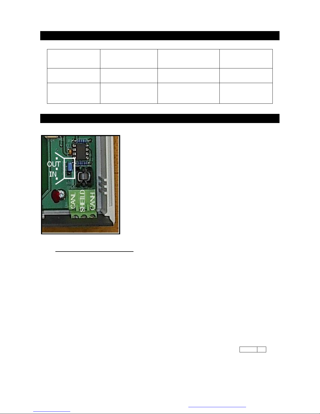
•Connect the CANBUS cable(s). See Fig 3.
•Connect the provided DB9 Serial Cable to the PC Interface. At the PC plug it into an available serial port.
Sometimes the Serial Port on the PC is not marked
, sometimes it is marked with the symbol l 0 l 0 l and
sometimes there will be a label ‘Comm 1’ or ‘Comm 2’. If the available serial port on the PC is the older
25 pin type, purchase an adapter (DB9 to DB25) from an electronics retailer. For PC’s equipped only with
USB ports an adapter can be purchased in the computer aftermarket and used, but this may require the
assistance of a knowledgeable PC professional (depending on adapter model) and is not factory
supported. See Fig 3.
•Connect the provided Power Supply. See Fig 3.
•To load the provided PC Software, follow the instructions included with the CD. Generally, depending on
the version of Windows: Close all open programs on the PC. Insert the CD into the drive bay on the front
of the PC. Wait a few moments for the PC to recognize the CD. Open the CD by double-clicking the ‘My
Computer’ icon on the desktop, then double–click on the icon for the CD drive. From the icons/menu now
available double click on the file SETUP.EXE and the installation will begin immediately. You will be asked
to answer several questions as the installation proceeds – always choose the default answers. After this
section of the installation is complete, a window will open with an icon similar to an Olympic torch.
Minimize any open windows with the exception of the window with the torch icon. Place the mouse pointer
over this icon and while holding down the right hand button on the mouse, move the icon to an
unoccupied area of the desktop and release the right button. Close all of the open windows on the
desktop.
•Next, Install the Borland Database Engine. Re-open the CD by double-clicking on the ‘My Computer’ icon
on the desktop and then double–click the Icon for the CD Drive. You will find a file folder marked
BDEDISK1 or it may simply be marked ‘BDE’, double-click on it and then from the icons/menu now
available double click on the file SETUP.EXE and the installation will begin immediately. Once again,
choose all of the default answers for any questions. You will be advised when installation is complete.
•Restart the PC and start the software by double-clicking on the Icon. If you were not successful moving
the Icon for the software to the desktop, click on the ‘Start’ button in the lower left-hand corner of the
screen, click on ‘Programs’, click on ‘MDS2000 PC System’, then click the next ‘MDS2000 PC System’ from
the extended menu.
•Ignore any error messages the system generates at this point. Look at the top Menu bar and find the
‘Options’ button. Place the mouse pointer over ‘Options’ and single click the left mouse button. A drop
down menu will appear below the ‘Options’ button, move the mouse pointer down to the item ‘Comm Port’
and click on it. You will see another menu appear to the side listing ‘Comm 1’ to ‘Comm 4’. If you know
from the markings on the back of the PC which Comm Port you are connected to then click on that button.
If you don’t know, click on the ‘Comm 1’ button first and if it does not work (if this is the case you will get
an initial message ‘Please Wait – Checking Comms’ and then after a few moments an error message
appears ‘Retry Error – Cannot communicate with Conductor’) keep following these directions over and
over again, choosing each Comm Port in turn. When you have chosen the correct Comm Port you will get
a message in the center of the screen ‘Please wait finding I/O’s’. If the rest of the system is properly
connected the I/O indicator lights will turn green as the units are found. If the rest of the system is either
not connected or improperly connected you will get an error message ‘Network not found!’ If you get any
other kind of error message, consult the troubleshooting guide below.
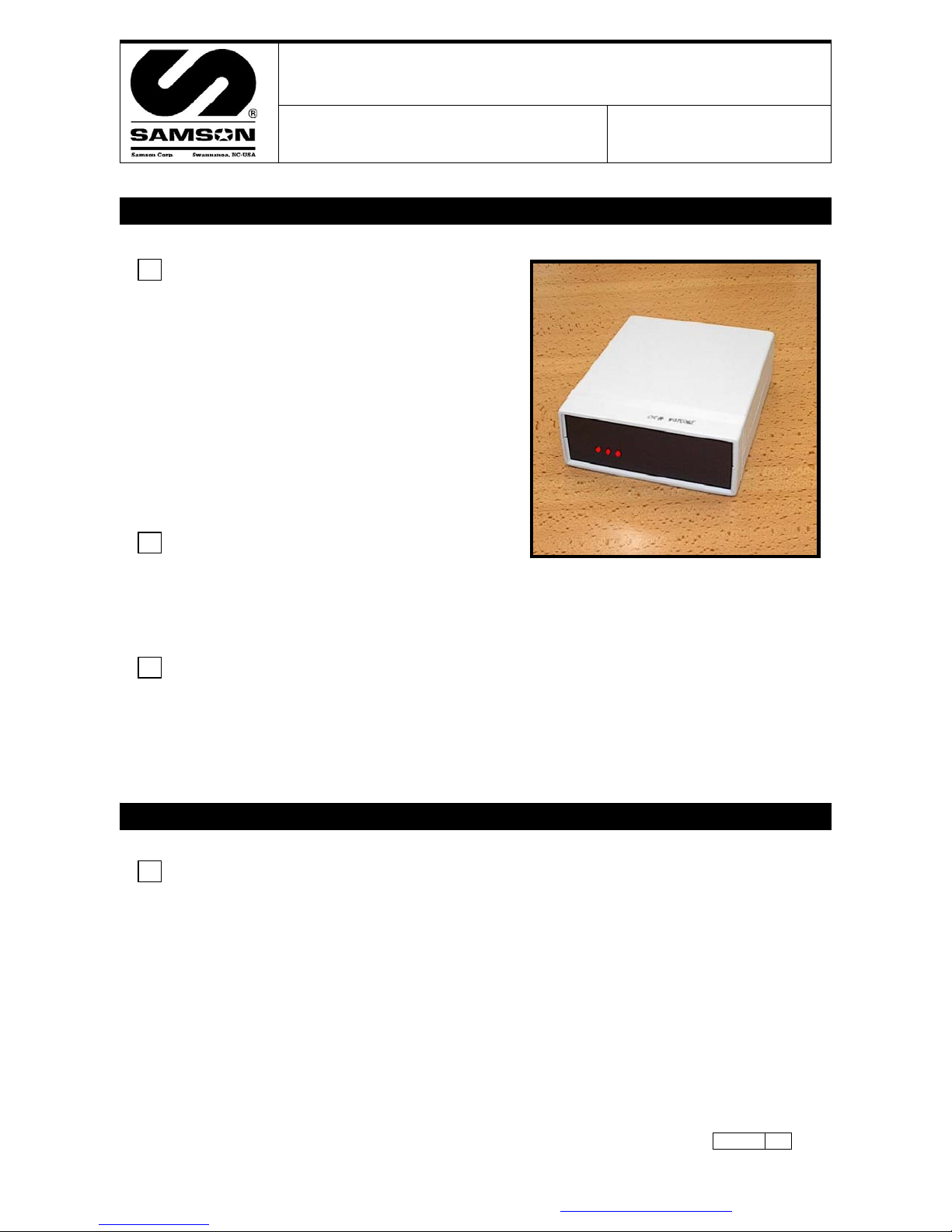
•There are three red LED lights on the face of the PC Interface for diagnostics purposes. From left to right
they are:
•LED1 = PC to Interface serial link. In normal operation this light will blink intermittently as the PC ‘talks’ to
the PC Interface and the Interface responds, and vice-versa. The blinking will normally be irregular but in
normal service it will light up every second or so, depending on what is happening on the system. When
sending the configuration the LED may periodically appear to be continuously glowing, as this operation
makes very intensive and continuous use of the comms, but once the configuration operation is complete
it will return to the normal blinking state. If this LED remains continuously glowing for an extended period
of time it indicates an error, consult the troubleshooting section below.
•LED2 = Power. This light should remain continuously glowing at all times when the unit is powered up. If
it is not on it indicates an error, consult the troubleshooting guide below.
•LED3 = CANBUS. This light indicates the condition of the communications from the PC Interface to the I/O
Units. In normal operation this light will blink intermittently as the PC Interface ‘talks’ the I/O units and
they respond. The blinking will normally be irregular but in normal service it will light up every second or
so, depending on what is happening on the system. When sending the configuration the LED may
periodically appear to be continuously glowing, as this operation makes very intensive and continuous use
of the comms, but once the configuration operation is complete it will return to the normal blinking state.
If this LED remains continuously glowing for an extended period of time it indicates an error, consult the
troubleshooting section below.
•See the System Overview guide for instructions on CANBUS Networking, Configuring, Addressing and
General System-wide Troubleshooting.
380310 2