Samsung Semiconductor ARTIK 530 User manual

SAMSUNG ELECTRONICS RESERVES THE RIGHT TO CHANGE PRODUCTS, INFORMATION AND SPECIFICATIONS WITHOUT NOTICE.
Products and specifications discussed herein are for reference purposes only. All information discussed herein is provided on an "AS IS" b asis, without warranties
of any kind. This document and all information discussed herein remain the sole and exclusive property of Samsung Electronics. No license of any patent,
copyright, mask work, trademark or any other intellectual property right is granted by one party to the other party under this document, by implication, estoppel
or other-wise. Samsung products are not intended for use in life support, critical care, medical, safety equipment, or similar applications where product failure
could result in loss of life or personal or physical harm, or any military or defense application, or any governmental procurement to which special terms or
provisions may apply. For updates or additional information about Samsung products, contact your nearest Samsung office. All brand names, trademarks and
registered trademarks belong to their respective owners.

Samsung Semiconductor, Inc. ARTIK 530 Development Board User Guide
Samsung Confidential
Specifications in this document are tentative and subject to
change.
2
TABLE OF CONTENTS
Table of Contents ................................................................................................................................................................... 2
List of Figures.......................................................................................................................................................................... 3
List of Tables ........................................................................................................................................................................... 3
Version History ...................................................................................................................................................................................... 4
Handling Guide....................................................................................................................................................................... 5
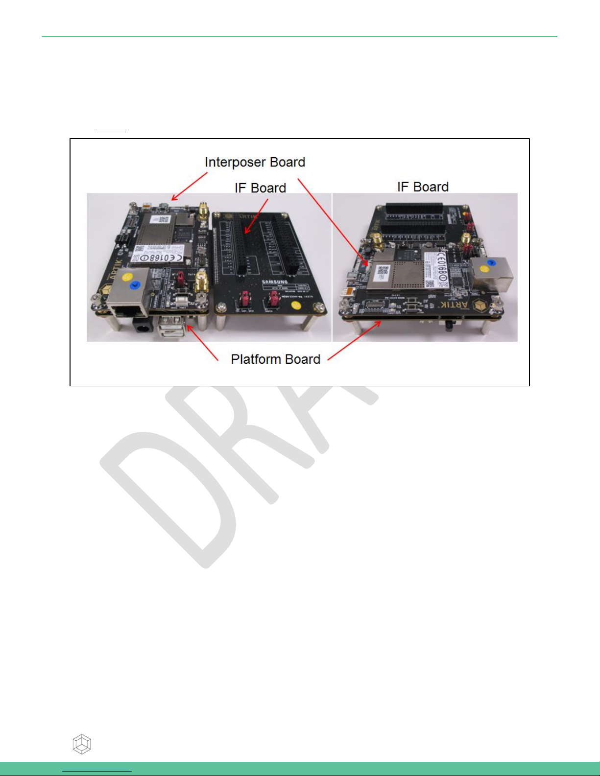
ARTIK 530 Development Board Overview........................................................................................................................... 6
features.................................................................................................................................................................................................. 6
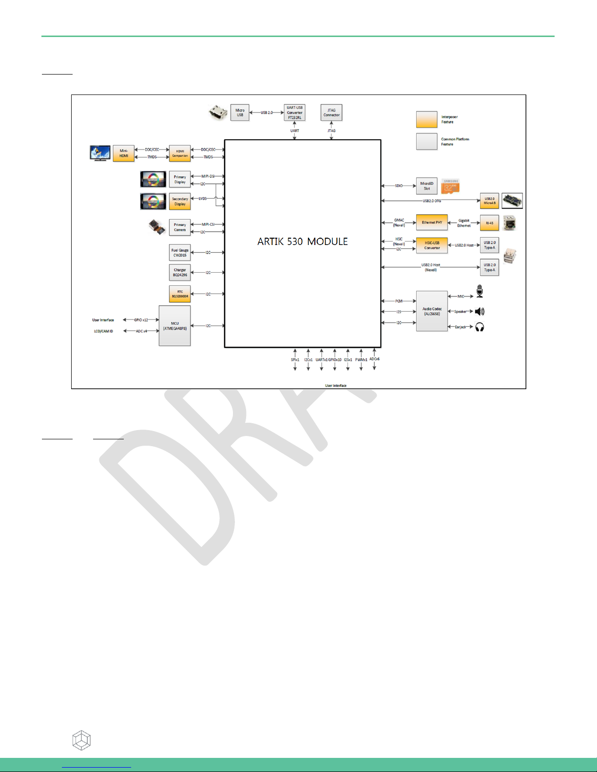
Block diagram ....................................................................................................................................................................................... 7
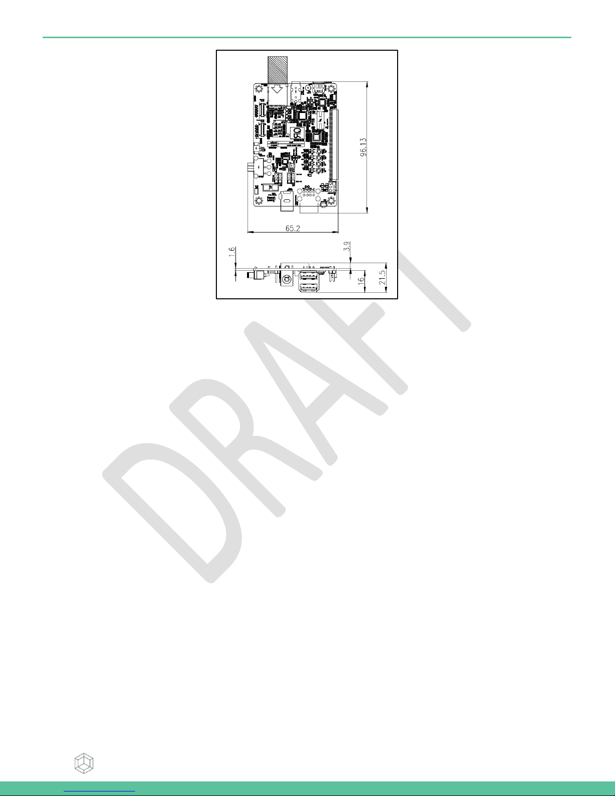
Mechanical Drawings ........................................................................................................................................................................... 7
ARTIK 530 Module ................................................................................................................................................................ 10
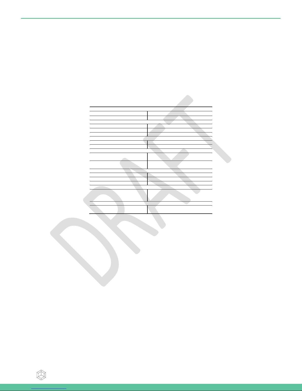
ARTIK 530 Module Specification........................................................................................................................................................ 10
ARTIK 530 Development Board Interposer Board........................................................................................................... 11
Interposer Board Boot mode Configuration.................................................................................................................................... 12
USB OTG............................................................................................................................................................................................... 13
HDMI 1.4a............................................................................................................................................................................................ 13
LVDS ..................................................................................................................................................................................................... 14
Ethernet................................................................................................................................................................................................ 14
Antenna................................................................................................................................................................................................ 15
ARTIK 530 Development Board Platform Board .............................................................................................................. 16
Configuration of External Power Source .......................................................................................................................................... 17
SD-Card Interface................................................................................................................................................................................ 17
EarJack Interface................................................................................................................................................................................. 18
MIPI DSI/CSI Interface......................................................................................................................................................................... 18
USB Host 2.0 Interface ....................................................................................................................................................................... 19
Connector to IF Board Interface........................................................................................................................................................ 20
ARTIK 530 Development Board IF Board .......................................................................................................................... 21
Preview on the ARTIK IF board .......................................................................................................................................................... 21
Configuration of external Power Source .......................................................................................................................................... 22
ARTIK 530 Development Board Booting ........................................................................................................................... 23
Serial Port Connection ....................................................................................................................................................................... 23
Terminal Emulator Installation ......................................................................................................................................................... 24
Power on the ARTIK 530 Development Board.................................................................................................................................. 25
Network Settings ................................................................................................................
오류! 책갈피가 정의되어 있지 않습니다.
How to use sftp ..................................................................................................................
오류! 책갈피가 정의되어 있지 않습니다.
How to use ssh ...................................................................................................................
오류! 책갈피가 정의되어 있지 않습니다.
Package installation ..........................................................................................................
오류! 책갈피가 정의되어 있지 않습니다.
Legal Information ................................................................................................................................................................. 27

Samsung Semiconductor, Inc. ARTIK 530 Development Board User Guide
Samsung Confidential
Specifications in this document are tentative and subject to
change.
3
LIST OF FIGURES
Figure 1. Preview of the ARTIK 530 Board ............................................................................................................................6
Figure 2. ARTIK 530 Development Board..............................................................................................................................7
Figure 3. Mechanical Drawing ARTIK 530 Development Board Interposer Board all dimensions are in [mm] ..........8
Figure 4. Mechanical Drawing ARTIK 530 Development Board Platform Board all dimensions are in [mm] .............9
Figure 5. ARTIK 530 Development Board Interposer Board Left Top Side, Right Bottom Side .................................. 11
Figure 6. ARTIK 530 Development Board Booting Switch Location................................................................................ 12
Figure 7. USB OTG Interface location on the Interposer Board...................................................................................... 13
Figure 8. HDMI 1.4a Interface location on the Interposer Board ................................................................................... 13
Figure 9. LVDS Interface location on the Interposer Board............................................................................................. 14
Figure 10. Ethernet Interface location on the Interposer Board .................................................................................... 14
Figure 11. Antenna location on the Interposer Board ..................................................................................................... 15
Figure 12. ARTIK 530 Development Board Platform Board Left Bottom Side, Right Top Side ................................... 16
Figure 13. Jumper Interface locations JP1-JP4 on the Platform Board ........................................................................... 17
Figure 14. SD-Card Interface location on the Platform Board ........................................................................................ 17
Figure 15. Ear Jack Interface location on the Platform Board ......................................................................................... 18
Figure 16. MIPI DSI Interface location on the Platform Board ........................................................................................ 18
Figure 17. MIPI CSI Interface Location on the Platform Board ....................................................................................... 19
Figure 18 USB2.0 Interface location on the Platform Board ........................................................................................... 19
Figure 19. Expansion Connector Interface location on the Platform Board ................................................................. 20
Figure 20. ARTIK 530 Development Board IF Board ......................................................................................................... 21
Figure 21. Jumper Interface locations J20, J21 on the IF Board ....................................................................................... 22
Figure 22. Typical Linux Serial Console .............................................................................................................................. 23
Figure 23. USB Serial Cable hooked up to the Platform Board....................................................................................... 24
Figure 24 Connection Power adaptor with development Board .................................................................................... 25
Figure 25. Power switch location on the development Board ........................................................................................ 25
Figure 26. Power button location on the development Board ....................................................................................... 26
LIST OF TABLES
Table 1. Main Features of the ARTIK 530 Module............................................................................................................. 10
Table 2. Boot option that can be set on the Interposer Board ....................................................................................... 12
Table 3 Antenna spec ........................................................................................................................................................... 15
Table 4. Connector J2............................................................................................................................................................ 21
Table 5. Connector J3............................................................................................................................................................ 22

Samsung Semiconductor, Inc. ARTIK 530 Development Board User Guide
Samsung Confidential
Specifications in this document are tentative and subject to
change.
4
VERSION HISTORY
Revision
Date
Description
Maturity

Samsung Semiconductor, Inc. ARTIK 530 Development Board User Guide
Samsung Confidential
Specifications in this document are tentative and subject to
change.
5
HANDLING GUIDE
Precaution against Electrostatic Discharge
When using the ARTIK 530 Board, ensure that the environment is protected against static electricity:
Contamination
Do not use the ARTIK 530 Board in an environment exposed to dust or dirt adhesion.
Temperature/Humidity
The ARTIK 530 Board is sensitive to:
1. Environment
2. Temperature
3. Humidity
High temperature or humidity deteriorates the characteristics of ARTIK 530 Board, therefore, do not store or use the ARTIK
530 Board under such conditions.
Mechanical Shock
Do not to apply excessive mechanical shock or force on the ARTIK 530 Board.
Chemical
Do not expose the ARTIK 530 Board to chemicals. Exposure to chemicals leads to reactions that deteriorate the
characteristics of the ARTIK 530 Board.
EMS (Electro Magnetic Susceptibility)
Strong electromagnetic waves or magnetic fields may affect the characteristics of the ARTIK 530 Board during the operation
under insufficient PCB circuit design for Electro Magnetic Susceptibility (EMS).

Samsung Semiconductor, Inc. ARTIK 530 Development Board User Guide
Samsung Confidential
Specifications in this document are tentative and subject to
change.
6
ARTIK 530DEVELOPMENT BOARD OVERVIEW
FEATURES
The ARTIK 530 Development Board consists of 1x Interposer Board , 1x Platform Board, and 1x IF Board. The Interposer
Board does include the ARTIK 530 Module. The ARTIK 530 Development Board is an affordable approach for developing an
IoT solution. Figure 1 show the locations of the various boards that make up the ARTIK 530 Development Board.
Figure 1. Preview of the ARTIK 530 Board

Samsung Semiconductor, Inc. ARTIK 530 Development Board User Guide
Samsung Confidential
Specifications in this document are tentative and subject to
change.
7
BLOCK DIAGRAM
Figure 2 shows the block diagram of the ARTIK 530 Development Board, if you want more information on the ARTIK 530
Module please consult the ARTIK 530 Module Datasheet.
Figure 2. ARTIK 530 Development Board
MECHANICAL DRAWINGS
Figure 3 and Figure 4 show the ARTIK 530 Development Board Interposer Board and the Platform Board respectively.

Samsung Semiconductor, Inc. ARTIK 530 Development Board User Guide
Samsung Confidential
Specifications in this document are tentative and subject to
change.
8
Figure 3. Mechanical Drawing ARTIK 530 Development Board Interposer Board all dimensions are in [mm]

Samsung Semiconductor, Inc. ARTIK 530 Development Board User Guide
Samsung Confidential
Specifications in this document are tentative and subject to
change.
9
Figure 4. Mechanical Drawing ARTIK 530 Development Board Platform Board all dimensions are in [mm]

Samsung Semiconductor, Inc. ARTIK 530 Development Board User Guide
Samsung Confidential
Specifications in this document are tentative and subject to
change.
10
ARTIK 530 MODULE
The ARTIK 530 Development Board contains the ARTIK 530 Module. This section will describe some of the main features of
this module. For more information on the ARTIK 530 Module please consult the ARTIK 530 Module datasheet.
ARTIK 530 MODULE SPECIFICATION
The ARTIK 530 Module is designed for IoT devices and it contains a lot of functions based on a Linux system. Not only
multimedia functions but also network functions for example Wi-Fi or ZigBee. In addition the ARTIK 530 Module has mass
storage functionality and its own security solution. Table 1 shows the main features of the ARTIK 530 Module that is part of
the ARTIK 530 Development Board.
Table 1. Main Features of the ARTIK 530 Module
Processor
CPU
4x ARM® Cortex-A9@1.2GHz
GPU
3D graphics accelerator
Media
Camera I/F
4-Lane MIPI CSI
Display
4-Lane MIPI DSI up to FHD@24bpp
Audio
I2S audio interface
Memory
DRAM
512MB DDR3 @ 800MHz
FLASH
4GB eMMC
Security
Secure Element
Secure point to point authentication
and data transfer
Trusted Execution
Environment
Trustware
Radio
WLAN
IEEE 802.11a/b/g/n
Bluetooth
4.2+LE
802.15.4
ZigBee + Thread
Power Management
PMIC
Provides all power of the ARTIK 530
Module using on board bucks and
LDOs
Interfaces
Analog and Digital I/O
GPIO, I2C, SPI, UART, SDIO, USB
2.0, JTAG, Analog Input

Samsung Semiconductor, Inc. ARTIK 530 Development Board User Guide
Samsung Confidential
Specifications in this document are tentative and subject to
change.
11
ARTIK 530 DEVELOPMENT BOARD INTERPOSER BOARD
The Interposer Board as depicted in Figure 5 highlights the most important components on the Interposer board.
Figure 5. ARTIK 530 Development Board Interposer Board Left Top Side, Right Bottom Side

Samsung Semiconductor, Inc. ARTIK 530 Development Board User Guide
Samsung Confidential
Specifications in this document are tentative and subject to
change.
12
INTERPOSER BOARD BOOT MODE CONFIGURATION
This section describes the various boot modes that are supported on the ARTIK 530 Development Board. Table 2 and Figure 6
show how to manipulate SW4 and where SW4 is located on the Interposer Board to set the various booting options that are
available on the ARTIK 530 Development Board.
Table 2. Boot option that can be set on the Interposer Board
SW4
eMMc
1st Boot
SD Card
1st Boot
USB
1st Boot
AP_GPB13_SD0_BOOT
Off
Off
On
AP_GPB15_SD1_BOOT
Off
Off
On
AP_GPB4_VID1_3_BOOT
Off
On
X
Figure 6. ARTIK 530 Development Board Booting Switch Location

Samsung Semiconductor, Inc. ARTIK 530 Development Board User Guide
Samsung Confidential
Specifications in this document are tentative and subject to
change.
13
USB OTG
The Interposer board has 1x USB OTG connector located as can be seen in Figure 7.
Figure 7. USB OTG Interface location on the Interposer Board
HDMI 1.4A
The Interposer board has 1x HDMI 1.4a connector (Micro D-Type) located as can be seen in Figure 8. The following video
formats are supported:
1. 480p/480i @59.94Hz/60Hz, 576p/576i@50Hz
2. 720p/720i @50Hz/59.94Hz/60Hz
3. 1080p/1080i @50Hz/59.94Hz/60Hz
Figure 8. HDMI 1.4a Interface location on the Interposer Board

Samsung Semiconductor, Inc. ARTIK 530 Development Board User Guide
Samsung Confidential
Specifications in this document are tentative and subject to
change.
14
LVDS
The Interposer board has 1x LVDS Interface containing 5x data channels and 1x clock channel, its location can be seen in
Figure 9. The available maximum resolution is 1920x1080@60fps.
Figure 9. LVDS Interface location on the Interposer Board
ETHERNET
The Interposer board has 1x Ethernet Interface, its location can be seen in Figure 10. The Ethernet Interface is based on
802.3az-2010 complying to the Energy Efficient Ethernet (EEE) standard. The maximum theoretical speed of the interface is
1000Mbps.
Figure 10. Ethernet Interface location on the Interposer Board

Samsung Semiconductor, Inc. ARTIK 530 Development Board User Guide
Samsung Confidential
Specifications in this document are tentative and subject to
change.
15
ANTENNA
Antenna which is enclosed in KIT has to be assembled on Interposer board if use Wifi/BT and Zigbee.
Antena spec can be seen in Table 3
Table 3 Antenna spec
Antenna type
Dipole Antenna
Antenna peak gain
+1.43(2.4GHz)/ +0.91(5GHz)
Frequency
2.4GHz, 5GHz (for Wi-Fi, BT, ZigBee)
Connector type
SMA-M
ANT.Size
108.7mm
Figure 11. Antenna location on the Interposer Board

Samsung Semiconductor, Inc. ARTIK 530 Development Board User Guide
Samsung Confidential
Specifications in this document are tentative and subject to
change.
16
ARTIK 530 DEVELOPMENT BOARD PLATFORM BOARD
The Platform Board as depicted in Figure 12 highlights the most important components on the Interposer board.
Figure 12. ARTIK 530 Development Board Platform Board Left Bottom Side, Right Top Side

Samsung Semiconductor, Inc. ARTIK 530 Development Board User Guide
Samsung Confidential
Specifications in this document are tentative and subject to
change.
17
CONFIGURATION OF EXTERNAL POWER SOURCE
Through selection of the Jumpers JP1-JP4 the IO power source can be selected to either DC-5V or to Charger Output. Figure 13
shows how to set the various jumpers to switch between power sources.
Figure 13. Jumper Interface locations JP1-JP4 on the Platform Board
SD-CARD INTERFACE
The Platform board has 1x SD-CARD interface supporting SD3.0 located as can be seen in Figure 14.
Figure 14. SD-Card Interface location on the Platform Board

Samsung Semiconductor, Inc. ARTIK 530 Development Board User Guide
Samsung Confidential
Specifications in this document are tentative and subject to
change.
18
EARJACK INTERFACE
The Platform board has 1x 4 pin ear jack interface supporting stereo audio as can be seen in Figure 15.
Figure 15. Ear Jack Interface location on the Platform Board
MIPI DSI/CSI INTERFACE
The Platform board has 1x MIPI DSI and 1x MIPI CSI interface. The location of the DSI Display interface can be seen in Figure
16. The location of the MIPI CSI interface can be seen in Figure 17.The MIPI DSI interface can operate at a maximum resolution
of WUXGA (1920x1200), whereas the MIPI CSI interface can have a static resolution of 5M pixels or a dynamic resolution for
video capturing of 1080P.
Figure 16. MIPI DSI Interface location on the Platform Board

Samsung Semiconductor, Inc. ARTIK 530 Development Board User Guide
Samsung Confidential
Specifications in this document are tentative and subject to
change.
19
Figure 17. MIPI CSI Interface Location on the Platform Board
USB HOST 2.0 INTERFACE
The Platform board has 1x USB 2.0 Interface. The location of the USB 2.0 interface can be seen in .
Figure 18 USB2.0 Interface location on the Platform Board

Samsung Semiconductor, Inc. ARTIK 530 Development Board User Guide
Samsung Confidential
Specifications in this document are tentative and subject to
change.
20
CONNECTOR TO IF BOARD INTERFACE
The Platform board has 1x expansion connector that can be seen in Figure 19. This connector enables expansion
Figure 19. Expansion Connector Interface location on the Platform Board
Table of contents