S&S Cycle Motorcycle Accessories Instruction manual

1
Instruction Sheet #51-1160
04-28-04
Copyright®, 2003
by S&S Cycle, Inc.
All rights reserved. Printed in the U.S.A. Because every industry has a leader
S&S Twin Cam Style Engine
Assembly and Installation Instructions
S&S Cycle, Inc.
14025 County Highway G Box 215
Viola, Wisconsin 54664
Phone: 608-627-2080 • Fax: 608-627-1488
Technical Service Phone: 608-627-TECH (8324)
Technical Service Email: [email protected]
Website: www.sscycle.com
For all S&S Twin Cam style Engine Assemblies with Twin Cam style or
optional Evolution style engine mounting.
All S&S Twin Cam style Engine Assemblies are
Type "A" style (non-counterbalanced).

2
SAFE INSTALLATION AND OPERATION RULES:
Before installing any S&S engine part, it is your responsibility
to read and follow all instructions. The rules below are for
your personal safety, and must be kept in mind at all times.
●Gasoline is extremely flammable and explosive under
certain conditions, and toxic when inhaled. Do not smoke
around gasoline. Perform the installation in a well-ventilated
area away from sparks or open flame.
●After installation, be sure all fuel lines are routed correctly
with clamps in place and tightened securely. Even with
protective cover, gas lines must not contact extremely hot
surfaces where they could melt or leak and catch fire.
●Compressed air and particles dislodged by
compressed air are potentially harmful. Wear protective
goggles when using compressed air and always direct
the air stream away from yourself and others nearby.
●Some solvents, degreasers and other chemicals are
harmful, especially to skin and eyes. Many chemical
compounds such as lacquer thinner are also flammable and
present a fire hazard. Read the manufacturer’s instruction
label for precautions and proper use. Use in a well ventilated
area and wear protective clothing to avoid personal injury.
●If the motorcycle has been running, wait until the engine
and exhaust pipes have cooled before performing any
mechanical work.
●Before beginning the installation, disconnect and remove
the battery to eliminate potential sparks and possible
inadvertent engagement of the electric starter while working
on the motorcycle.
●Read instructions thoroughly and carefully so all
procedures are completely understood before beginning
installation. Contact S&S if you have questions, if any steps
are unclear, or if any abnormalities occur during final
assembly, installation, or operation.
●Consult an authorized H-D service manual for correct
disassembly, reassembly, and installation procedures for any
parts that need to be removed or disassembled to facilitate
the installation.
●Use good judgment during assembly, installation, and
when operating the motorcycle. Good judgment begins with
a clear head. Don’t let alcohol, drugs, or fatigue impair
judgment. Perform installation when fresh and alert.
●For optimum performance and safety and to minimize
potential damage to the cylinder heads or other components,
use correct hardware and follow procedures outlined in S&S
instructions and authorized H-D service manual.
●Motorcycle exhaust fumes are toxic and must not be
inhaled. Run motorcycle only in a well ventilated area where
fumes can dissipate.
WARRANTY:
All S&S parts are guaranteed to the original purchaser to be
free of manufacturing defects in materials and workmanship
for a period of twelve (12) months from the date of purchase.
Merchandise that fails to conform to these conditions will be
repaired or replaced at S&S’s option if the parts are returned
to S&S by the purchaser within the 12 month warranty period
or within 10 days thereafter.
In the event warranty service is required, the original
purchaser must notify S&S of the problem immediately.
Some problems can be rectified by a telephone call and need
no further action. A part that is suspected of being defective
must not be replaced without prior authorization from S&S. If
it is deemed necessary for S&S to make an evaluation to
determine whether the part was defective, it must be
packaged properly to avoid further damage, and be returned
prepaid to S&S with a copy of the original invoice of purchase
and a detailed letter outlining the nature of the problem, how
the part was used, and the circumstances at the time of
failure. If after an evaluation was made by S&S and the part
was found to be defective, repair, replacement, or refund will
be granted.
ADDITIONAL WARRANTY PROVISIONS:
(1) No part shall be returned to S&S without first contacting
the company and obtaining a Return Authorization (RA)
number.
(2) S&S shall have no obligation in the event an S&S part is
modified by any other person or organization, or if another
manufacturer’s part is substituted for one provided by S&S.
(3) S&S shall have no obligation if an S&S part becomes
defective in whole or in part as a result of improper
installation, improper break-in or maintenance, improper use,
abnormal operation, or any other misuse or mistreatment.
(4) S&S shall not be liable for any consequential or incidental
damages resulting from the failure of an S&S part, the breech
of any warranties, the failure to deliver, delay in delivery,
delivery in non-conforming condition, or for any other breach
of contract or duty between S&S and a customer.
(5) S&S parts are designed exclusively for use on
motorcycles with Harley-Davidson style V-twin engines. S&S
shall have no warranty or liability obligation if an S&S part is
used in any other application.
IMPORTANT NOTICE:
Statements in this instruction sheet preceded by the
following words are of special significance:
WARNING
Means there is the possibility of injury to yourself or
others. CAUTION
Means there is the possibility of damage to the
motorcycle or a component.
NOTE
Other information of particular importance has been
placed in italic type.
S&S urges you to take special notice of these advisories.

S&S Basic Twin Cam Style Engines for Evolution Style Chassis*
Displacement Bore Stroke Fuel System Finish Assembled
Part Number
Natural 31-9340
124" 41⁄8"45⁄8"Carburetor 1Black 31-9341
Natural 31-9343
124" 41⁄8"45⁄8"S&S VFI 2Black 31-9344
S&S Basic Twin Cam Style Engines for Twin Cam Style Chassis*
Displacement Bore Stroke Fuel System Finish Assembled
Part Number
Natural 31-9330
124" 41⁄8"45⁄8"Carburetor 1Black 31-9331
Natural 31-9333
124" 41⁄8"45⁄8"S&S VFI 2Black 31-9334
*For installation in Stock Harley-Davidson Twin Cam Chassis only. Balanced version unavailable.
1Carbureted engines include an S&S IST ignition system and an S&S Super G or D carb.
2Fuel injected Engines include S&S Variable Fuel Injection (VFI) system with your choice of S&S tuned or teardrop induction, and either
Magnetti-Marelli or Delphi style S&S VFI Module
A. Introduction
S&S 124 Twin Cam Engines are available in two
versions The first version is designed and intended for
installation in a stock Harley-Davidson Twin Cam
Chassis. It will bolt directly to the stock transmission
and engine mounts of chassis designed for stock
unbalanced Twin Cam engines. The second version of
Twin Cam style Engine is machined with an Evolution
style rear motor mount. It may be installed in a stock or
aftermarket Evolution style chassis. Both versions are
available in natural aluminum or black powder coat
finish.
S&S 124" Twin Cam style Engines are available only in
a Basic version, meaning that some stock Harley-
Davidson or aftermarket Twin Cam style parts will be
needed to complete the engine. The extra parts
needed include: oil pump, oil pressure switch, cam
support plate, cam cover, tappets, tappet covers, and
oil filter bracket.
Installation can be performed by any Harley-Davidson
repair shop equipped to do complete engine overhauls.
No special tools other than those used in normal
engine building operations are required.
NOTES
●
Installation of a fuel injected engine in a motorcycle that
was originally equipped with a carburetor is fairly difficult
and expensive. This conversion requires a fuel pump
equipped gas tank as well as wiring harness.
●
All S&S Twin Cam Style engine assemblies are for Twin
Cam “A” (non-counterbalanced) engine applications, and
are not for use in Twin Cam “B” (counterbalanced)
applications.
●
Abalanced Twin Cam style Engine is not available from
S&S Cycle at this time.
3
*For installation in Stock Harley-Davidson Twin Cam Chassis only. Balanced version unavailable.
1Carbureted Long Blocks include an S&S IST ignition system and an S&S Super G or D carb.
2Fuel injected Long Blocks include S&S Variable Fuel Injection (VFI) system with your choice of S&S tuned or teardrop induction, and either
Magnetti-Marelli or Delphi style S&S VFI Module
I.Oil Tank, Fittings and Oil LIne
J.Exhaust System
K.Initial Start-up and Engine Break-In
L.Tuning Guidelines
M.Engine Specs and Torque Values
N.Service Intervals
O.Replacement Parts
Instruction Contents:
A.Introduction
B.Additional Features
C.Modification Notes
D.Engine to Frame Test Fit
E.Engine Assembly
F.Engine to Frame Assembly
G.Ignition System
H.Fuel System
Please read these instructions carefully before starting work. Proceed with the installation only after the instructions
are completely understood. These instructions should be supplemented by the appropriate OEM service manual for
your motorcycle. Follow all safety information.

B. Additional Features:
●Greater overall strength than stock crankcases,
especially in the front motor mount, an important
consideration in high performance applications.
●All oil passages between the crankcase and cam
support plate are o-ring sealed.
●Compatible with stock components. Use stock oil
pump, cam support plate, gear cover, etc.
●Uses 1999-2002 Timken style sprocket shaft bearing.
●Uses 2003-up pinion shaft bearing
S&S Twin Cam Style Engine Instructions often
refer to procedures described in other S&S
instructions or a Harley-Davidson Service Manual.
These materials should be cross-referenced as
necessary.
IMPORTANT
Before proceeding, verify that serial numbers on
crankcases match numbers on packing carton and
certificate of origin. Contact S&S immediately if
numbers do not match.
NOTE - Valid certificate of origin is required for any transfer
or sale of longblock assemblies. Certificate of origin is
required to title and license any motorcycle which is to be
driven on public streets and highways.
4
Dynomometer chart showing typical horsepower and torque curves for S&S 124” Twin Cam style engine.
Horsepower and torque curves will vary, dependant on the engines state of tune, and the ignition and fuel
systems used on the completed engine.
Torque
Horsepower

5
C. Modification Notes
S&S Cycle cautions against modifying these
crankcases due to the possibility of damaging or
weakening them. Modifying S&S crankcases in any
fashion voids all manufacturer warranties. Should the
customer elect to modify the crankcases regardless, it
is imperative that they and the information tag attached
to them be inspected beforehand to confirm that the
correct model, style, bore size, etc. have been
provided. The customer must confirm that crankcases
and related parts are correct before assembling them
or having them modified in any manner, and assumes
all liability for modifications.
Under no circumstance will S&S be held responsible
for expenses related to the modification of any S&S
part in the event warranty service is required. Modified
parts will not be accepted for credit or exchange. This
will apply regardless of cause or fault: customer,
retailer, manufacturer, or other.
For further information, contact S&S Technical Services
at 608-627-8324, FAX 608-627-0766 or e-mail
NOTE - “Modification” includes but is not limited to
appearance changes such as painting, powdercoating,
plating, and polishing. Proper preparation for these
procedures as well as the processes themselves may
require the use of polishing compounds, chemicals or
procedures that are potentially harmful to crankcases.
CAUTION - Passages and internal cavities may become
obstructed by residues from materials used to polish,
paint, plate or powdercoat surfaces. Additionally,
surface finishing processes can damage critical
machined surfaces. Any of the above may cause
premature wear, damage or failure of other engine
components as well as the crankcases themselves.
Glass bead and polishing residues are abrasive and
can be difficult to remove from recesses and small
passages. Abrasive residues can cause oil
contamination and extensive engine damage. Engine
damage caused by powder coating, polishing, glass
bead blasting, or other modification will not be covered
under warranty.
Powder Coating - Subjecting heat-treated alloys such
as those used in S&S crankcases to excessive heat
can drastically alter their strength and their critical
properties. The degree of change depends upon the
temperatures reached and the duration of exposure.
When powder coating or otherwise processing alloy
parts, S&S exposes them to a maximum temperature
of 370°F for no longer than 20 minutes. Under no
circumstances should parts be heated past 400°F!
S&S strongly recommends trial-fitting every engine
before frame is painted or powder coated.
D. Engine to Frame Test Fit
NOTE - The engine must be fitted to the frame it is installed
into. It must rest squarely on its attachment points, and
bolted solidly to the frame without stressing the engine
case at any point. If possible, crankcase should be
positioned in motorcycle frame before assembly to check
alignment and clearances. The same clearancing and
alignment steps must be taken for assembled engines.
Performing the clearance alignment checks with a bare
case is convenient due to the reduced weight.
CAUTION - Failure to correctly mount the engine can
cause problems not covered under warranty including
but not limited to, excessive vibration, driveline mis-
alignment, and broken castings.
CAUTION - Do not carry crankcase by the studs. It
stresses the crankcase and studs in ways they are not
designed to handle. Also, it is easy to drop and damage
the case when it is carried by the studs.
1. Test-fit instructions for Twin Cam style cases
with stock Twin Cam style engine mounts.
1. Assemble case halves using case bolts.
Tighten to snug. Torquing bolts to final
specification is not necessary.
2. Clean frame engine mounts and carefully
remove any irregularities from mounting
surfaces. Also inspect crankcase mounting
bosses for burrs.
3. Position case in frame, check for clearance at
frame, and alignment to transmission. It is a
good idea to replace rubber engine mounts at
this time. Old mounts deform over time and
can induce unwanted stresses on the engine
case.
6
CAUTION - Improper alignment of engine and frame
mounts may cause abnormal stresses resulting in
damage to crankcases or other parts.
2. Test-fit instructions for Twin Cam style cases
with Evo Style motor mounts.
1. Assemble case halves using case bolts.
Tighten to snug. Torquing bolts to final
specification is not necessary.
2. Clean frame engine mounts and carefully
remove any irregularities from mounting
surfaces. Also inspect crankcase mounting
bosses for burrs.
3. Position case assembly in frame.
4. Install engine mounting bolts in motor mounts,
and check clearance between mounting
bosses on cases and frame and any other
areas where frame and cases may contact
each other. Bolts may be difficult to install if
contact is severe.
5. If cases contact frame, remove them and
relieve just enough material in offending area
to provide clearance.
6. Place cases in frame, install one rear mounting
bolt and snug nut.
7. Measure gap between crankcase mounting
bosses and frame motor mounts with feeler
gauge to determine if shimming is required.
8. If gap exists, fabricate shim just thick enough
to fill gap
9. Install opposite corner shim and mounting bolt
and nut, and tighten identical to other bolt.
10. Check other corners with feeler gauge to
confirm thickness required is same as before.
If not, determine cause and correct.
NOTE - S&S Twin Cam style crankcase installation in
Evolution style motorcycle frame is essentially the same as
stock, although additional clearancing and shimming may
occasionally be required. When this style of case is solid
mounted instead of rubber mounted, additional care must
be taken in installing the case. Main areas of concern are
between cases and frame motor mounts. Checking
clearance around and between case mounting bosses and
frame is necessary to insure that crankcase rests squarely
on motor mount pad and no stress is applied to crankcases
when mounting bolts are tightened. Shimming may be
required to compensate for variances between frames.
E. Engine Assembly
NOTES:
●
S&S supplies Torco Engine Assembly Lube with each
Engine. It should be used as specified in following
instructions. While other brands of assembly lube are
acceptable, other lubricants are not. In no instance should
an aerosol lubricant be substituted for assembly lube.
●
While S&S has made every effort to insure that parts are
correct, it is the engine builder’s responsibility to confirm fit
and finish of all parts provided with Engines prior to
assembly. Parts are deburred at S&S and usually require
no further preparation, but must also be inspected by
installer. Individual parts should not be removed from
protective plastic wrappers until needed. After removal
from plastic, it is imperative that parts be thoroughly
cleaned and dried, preferably with compressed air. When
present, rust preventative must be completely removed.
Additionally, gaskets must be closely inspected for particles
that could become dislodged and damage engine. If
assembly of Engine must be interrupted, seal openings and
cover engine with plastic to protect from destructive
contaminants.
Picture E2
Picture E1

CAUTION - Failure to observe the above may result in
engine damage not covered under warranty.
1. Crankcase preparation before assembly.
NOTES - S&S crankcases are sold in matched sets only.
Individual case halves are not available.
S&S Twin Cam style engines are shipped with cylinder
studs installed Before assembling engine, verify that the
lower collar of each stud is contacting the case deck, and
that the studs are torqued to 10 ft.-lbs.
1. Disassemble crankcases & wash in hot, soapy
water. Rinse case halves and blow dry with
compressed air. Check all internal passages. Coat
bearing surfaces with a light oil to prevent rust.
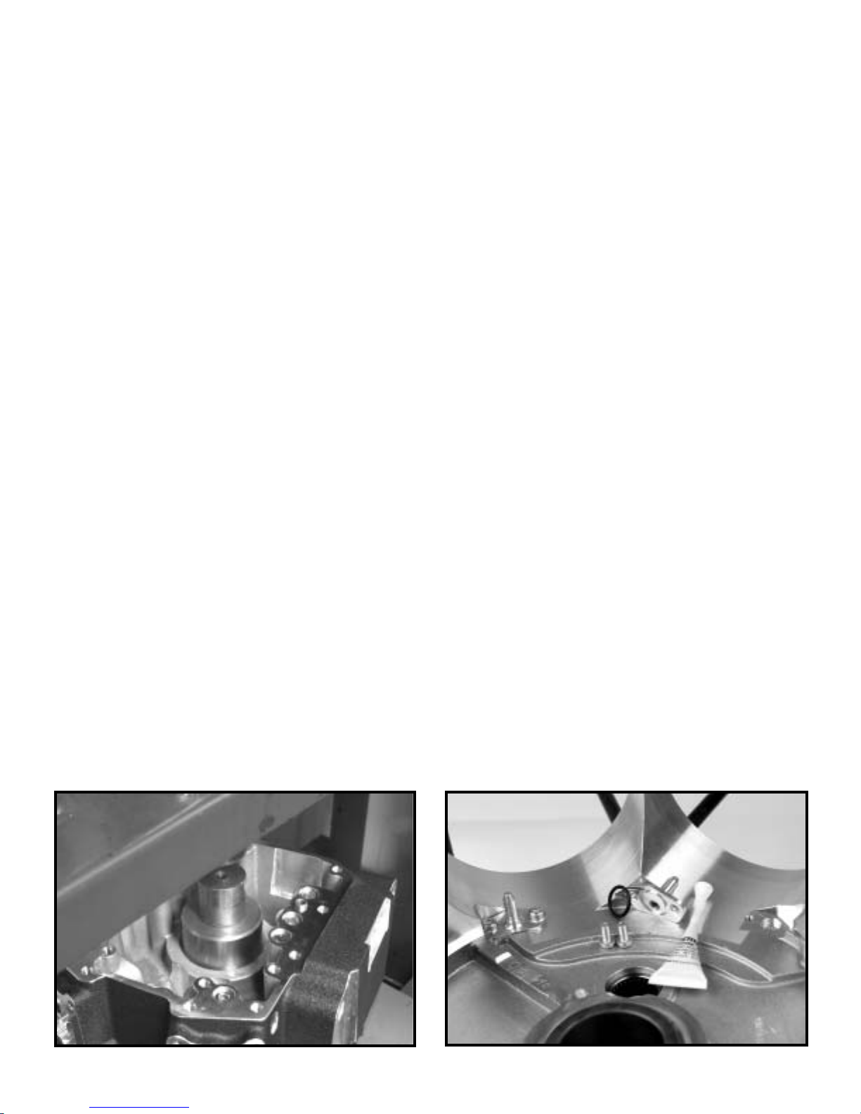
2. Install pinion bearing into right side case half.
See Picture E1.
a. Lubricate outer race of pinion bearing and
crankcase pinion bearing bore.
b. Using a suitable arbor, press pinion
bearing into bore so that it is centered
between the two snap ring grooves.
CAUTION - press only on outer race of bearing. Do not
press on inner race, bearing damage will occur.
c. Install snap ring into groove on each side
of bearing.
NOTE - If one side of the snap ring has a sharp corner and
one edge is rounded, install the ring with the sharp corner
facing out from the bearing
3. Install piston oilers into right-side crankcase.
a. Lubricate o-ring with engine oil and install
in piston oiler.
b. Apply Loctite 243 to screws. Install oilers,
tighten screws to 25 in-lbs. See Picture E2.
4. Install two case alignment dowels and o-rings
into right side crankcase.
NOTE - O-rings must be installed. O-rings that are missing
or damaged will cause oil leakage.
2. Install flywheels in crankcase.
1. Thoroughly clean parts according to
instructions previously mentioned. Apply coat
of assembly lube to bearing surfaces.
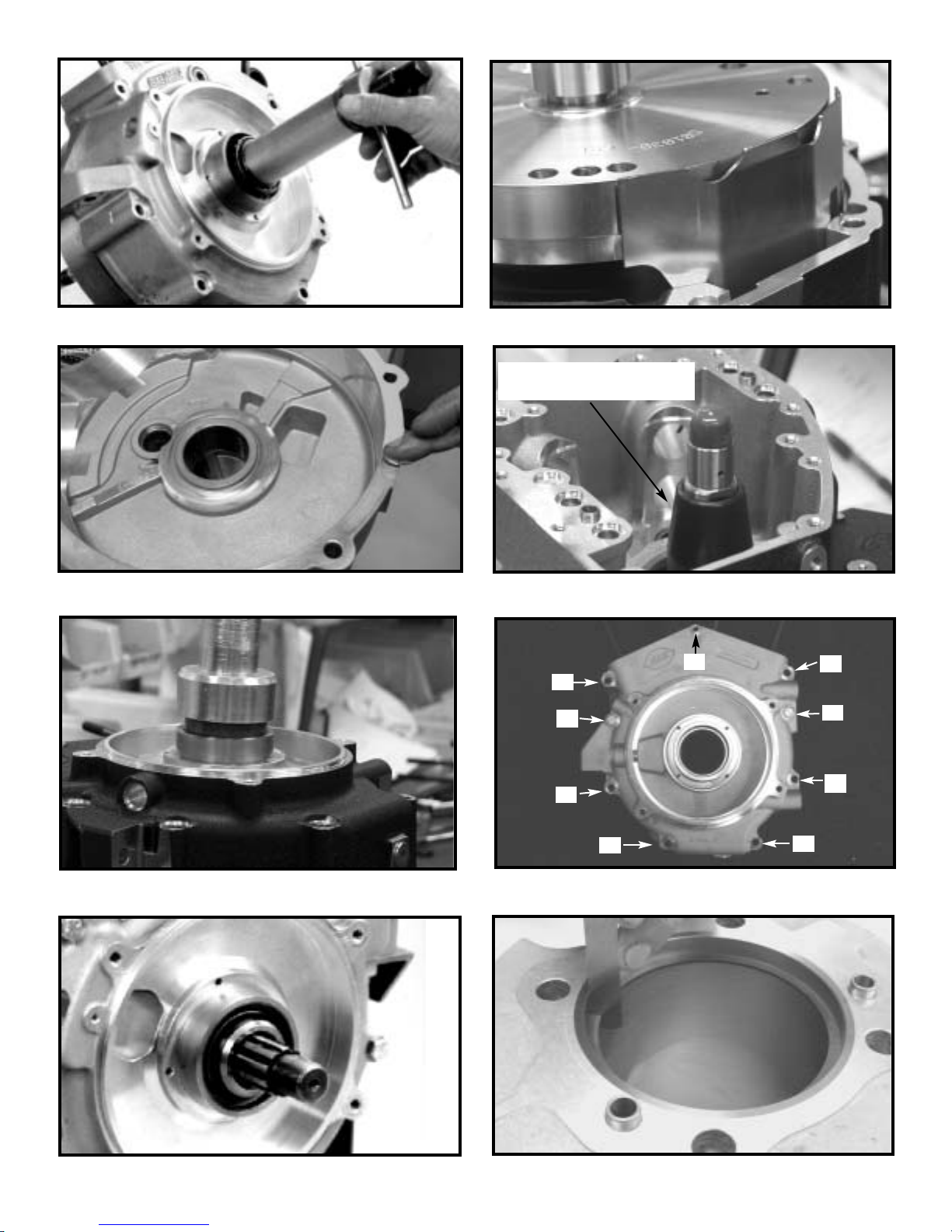
2 Place flywheel assembly onto a suitable
holding fixture, with sprocket shaft pointing up.
See Picture E3.
3. Install case and Timken bearing onto shaft with
appropriate tool. See Picture E4.
NOTE - Do not use a press to install sprocket shaft
bearings, as this can push flywheels out of true. Correct
bearing installation tools are available from Harley-
Davidson, Jim’s Machine, and other sources.
4. Place left side crankcase half over sprocket
shaft and onto bearing, insuring that
connecting rods are in correct positions.
See Picture E5.
5. Install included Timken bearing spacer.
See Picture E6.
6. Lubricate rollers of remaining Timken bearing
with assembly lube. Apply assembly lube to
bearing inner race and sprocket shaft bearing
surface.
7. Install bearing on shaft with appropriate tool.
See Picture E7.
8. Place assembled left case half and flywheel
assembly onto a suitable holding fixture, with
pinion shaft pointing up.
9 Lubricate pinion bearing and pinion shaft inner
bearing race with assembly lube.
3. Assemble crankcase halves
1. Install baffle plate in bottom of left side case.
Secure with two screws and blue Loctite.
See Picture E8.
2. Wipe down mating surfaces of crankcase
halves with lacquer thinner. Remove residue
with clean, dry cloth, then apply sealant to
both crankcase halves. Take care to avoid
areas where sealant might reach inside of
engine. If applicable, allow sealant to cure
according to manufacturer’s instructions
See Picture E9.
NOTE - S&S uses Threebond 1104 to seal crankcase.
Use any sealant carefully to prevent excess from entering
engine and obstructing oil passages or contaminating oil
supply.
7

3. Coat right main bearing and race with
assembly lube. , then join left and right
crankcase halves.
4. Tighten 5⁄16" case bolts to 18 ft-lbs, tighten 1⁄4"
center bolt to 120 in-lbs. in the sequence
shown. See Figure 1.
5. Install drive sprocket spacer and sprocket
shaft oil seal in main bearing race of left case.
Spring side of seal faces out. See Pictures
E11 and E12.
NOTE - Drive sprocket spacer is not incuded with S&S
engine. Spacer must be re-used from previous installation,
or sourced elsewhere
6. Allow crankcase sealant to cure per mfr.’s
instructions, then pour four ounces of motor oil
over bearing end of connecting rod assembly
and into flywheel cavity. Rotate flywheels
several times to distribute oil over connecting
rod bearings. Assembly should turn freely and
without binding.
CAUTION - Do not carry crankcase by the studs. It
stresses the crankcase and studs in ways they are not
designed to handle. Also, it is easy to drop and
damage the case when it is carried by the studs.
4. Install pistons and cylinders
1. Identify front and rear pistons. The rear piston
will have a notch in the skirt for clearance with
the front piston. The rear piston is to be
installed with this notch to the center of the
engine, or towards the front of the motorcycle.
Picture E5
8
Picture E3 Picture E4
Picture E6
Sprocket shaft bearing spacer
determines shaft end play
9
Use tool to guide bearing
rollers onto inner race
Picture E9
Picture E12
Picture E10
Picture E13
Picture E11 Figure 1
Picture E7
1
2
3
4
5
6
78
9
Picture E8
10
2. Inspect pistons, especially areas around
machined surfaces such as ring grooves and
wristpin holes. De-burr as necessary, taking
care to remove particles that could become
dislodged inside engine.
3. Measure ring end gaps and adjust as
necessary. See Pictures E13 and E14
a. Compression ring end-gaps should be
between .017” to .025”.
b. Oil ring rail end-gaps should be between
.015” to .035”.
4. Thoroughly clean cylinders, pistons, rings,
wristpins, and wristpin retainers in solvent,
then hot, soapy water. Take special care to
flush oil passages. Dry all with compressed air,
lightly coat all bare steel surfaces with
assembly lube, and place on clean, dry
surface.
5. S&S recommends installing all cylinder base
gaskets dry. Be sure holes in gaskets align
with cylinder base dowels and oil holes.
NOTE - cover cylinder studs with rubber hose to protect
piston and rings until cylinders are installed.
6. Install rings on pistons.
NOTE - The high wrist pin location on 124” pistons requires
an additional support for the oil rings at the gap on each
side of the wrist pin. This stiff ring should be installed first.
a. Install oil ring lower support in bottom
piston ring groove,with the dimple facing
down, and located in piston pin gap.
b. Lubricate wristpin, wristpin bushing, and
wristpin bore in piston with assembly lube.
Raise the previously installed support ring
in the lower groove to allow the wrist pin to
slide in under it. Install wristpin through
piston and connecting rod, secure with
new retaining clips, two per piston.
c. The moly-faced ring is installed in the top
piston ring groove, chamfer-side up.
d. The plain cast ring is installed in the
second piston ring groove, dot up.
e. Install the oil ring expander in the lower
ring groove (on top of the previosly
installed support ring), then install one oil
ring rail on either side of the expander.
f. Stagger all ring end-gaps
NOTE - S&S recommends the use of clip installer, part
number HD 42317, available from Kent-Moore, through
Harley-Davidson, or similar tool, for clip installation.
See Picture E15.
7. Install cylinder head alignment dowels in
cylinder.
8. Apply very light film of motor oil to piston skirts
and cylinder bores and install rear cylinder.
Install rear cylinder head, referring to following
section as necessary.
NOTE - On Twin Cam style Engine, if engine builder
chooses to install front cylinder before installing rear head,
rear cylinder should be temporarily secured with head bolt
and washers. If cylinder is not secured, piston can lift
cylinder and disturb base gasket if flywheels rotated.
9. Repeat piston installation for front cylinder and
cylinder head.
Picture E15
Picture E14

11
5. Install cylinder heads
1. Place head gasket on top of cylinder. Locate
on dowels installed in cylinder.
NOTE - Head gaskets should be installed clean and dry.
2. Before installing heads spin each head bolt
down on its respective stud to be sure threads
are clean and free of contamination. Place a
drop or two of oil on threads and under head of
each head bolt just prior to final assembly.
3. Bolt heads on cylinders. Use three stage
procedure and torque values. See Figure 2.
NOTE - If different camshafts, or S&S heads assembled by
other source are used, engine builder must confirm lift
capability of valve springs and collars as well as valve-to-
valve clearance. Refer to Installation Information for S&S
Twin Cam Style Camshafts.
CAUTION - Failure to establish correct clearances can
cause extensive engine damage not covered under
warranty.
NOTE - Light coating of oil on head bolt threads minimizes
friction so torque values will not be distorted. It cannot be
emphasized enough that these steps must be done carefully.
Maintaining a good head gasket seal depends on it.
CAUTION - Improper torquing sequence and head bolt
torque values may cause head gasket failure.
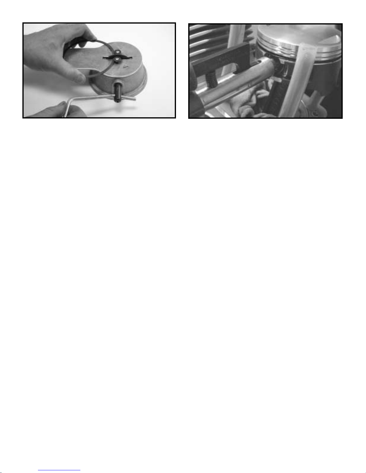
6. S&S Reed Valve installation
The S&S Reed Valve Assembly #31-2071 included
with the crankcase is an effective way to control
internal air pressures inside the crankcase, reducing
oil carry over, blow-by, and oil leakage. It is a one-way
valve that allows for the smooth passage of air
through and out of the engine breathing system.
Installation of the S&S Reed valve is optional. It is not
required for crankcase assembly. However, its use is
highly recommended. It installs easily, and requires
no extra machining. Refer to the included iinstructions
to install the Reed Valve Assembly. See Picture E16.
NOTE - S&S recommends using the S&S Reed Valve in
conjunction with the OEM oil pump only.
7. Camshaft and cam plate installation.
S&S Camshafts install using the instructions
packaged with them. Other camshafts install per
the manufacturers instructions.
CAUTION: S&S Twin Cam style crankcases require
installation of seven o-rings (S&S #50-8066) between the
case and cam support plate. (see section “O” item 13)
8. Oil pump, lifters, lifter covers, and cam cover
installation.
These and any other components not included with
the engine kit, install per appropriate OEM service
manual.
Stage 1 8 Ft. Lbs.
Stage 2 18 Ft. Lbs.
Stage 3 Turn additional 90O
12
43
Rear Head
21
34
Front Head
T
op
Vi
ew
Driveside
Camside
Figure 2
S&S Reed Valve assembly and wave washer
Picture E16

9. Compression releases and rocker cover
installation.
Refer to the included instructions to install the
compression releases and rocker covers
NOTES:
●
If S&S compression releases will be installed, it is much
easier to install them before the rocker covers are installed
and the engine is installed in the frame. S&S die-cast Twin
Cam style rocker covers or similar rocker covers with a
center hole or “chimney” must be used if S&S electric
compression releases are to be installed.
●
Some installations may have limited rocker cover to
frame clearance and require installing the rocker covers
after placing the engine in the frame.
F. Engine To Frame Assembly
The engine should be installed into the frame after the
engine is assembled, but before the ignition, fuel,
exhaust, and oil system components are installed.
1. Follow the engine to frame fitting instructions in
section D
2. Replace all other motorcycle components
removed for engine installation. Consult authorized
H-D service manual for installation procedure for
stock parts not covered in S&S instructions.
NOTE - On certain models it may be necessary to switch
the shift linkage to the outside of the shift lever. Make
certain that there is clearance between the shifter rod and
the engine crankcases.
G. Ignition System Installation
1. All Carbureted S&S Twin Cam style engine
assemblies come with an S&S IST (Intelligent
Spark Technology) ignition. Use of this ignition
system is highly recommended. All aspects of
ignition timing-- advance, retard, and curves are
handled automatically by the S&S IST ignition.
2. Once the IST ignition has been installed per the
included instruction sheet #51-1155, no other
adjustments are necessary
NOTES:
●
If the S&S IST ignition is not used, S&S recommends
using electronic ignition with adjustable advance curve in
S&S Twin Cam Style engines. Adjustable curve permits
slowing rate of advance to control or eliminate pinging
under heavy load or when elevated temperatures or poor
quality gasoline encountered.
●
All other ignition systems other than the included S&S
IST ignition install per manufacturers instructions.S&S
recommends setting the total ignition advance to 28
degrees. Timing degree recommendations given by S&S
take precedence over the ignition manufacturers
instructions
CAUTION- Timing that is too advanced will result in
detonation and engine damage. Timing that is too
retarded will result in engine over-heating and engine
damage. (This caution applies only to installations
other than the S&S IST Ignition)
CAUTION If S&S determines that engine damage was
caused by improper ignition timing, repair will not be
covered under warranty.
Excessive ignition advance will cause engine to kick
back against the starter during start-up and “buck” when
ridden at steady speed with partial throttle. An advanced
condition can also cause pinging or ignition knock and
possible piston damage. These symptoms may not be
noticed if electronic ignition with “soft” advance curve is
used.
Excessive ignition retard causes sluggish performance
and severe overheating with possible subsequent damage
to the engine, and must also be avoided. Immediate or
rapid exhaust pipe discoloration is usually a sign of
retarded ignition timing.
12
H. Fuel system installation and tuning
NOTES - S&S Engine assemblies are available with either
carbureted or fuel injected systems.
Assembled Engines are shipped with the
carburetor or fuel injection system installed. Refer to
the included instructions for operation and tuning .
Unassembled Engines are shipped with the fuel
system packaged separately. Refer to the included
instructions for installation and tuning .
1. Install fuel system.
1. Engine asemblies supplied with Super “G”
carburetors, refer to included instruction Sheet
#51-1012.
2. Engine assemblies supplied with Super “D”
carburetors,refer to included Special
Application Racing Carburetor Supplement for
additional information.
3. Engine assemblies supplied with fuel injection,
refer to included Induction System instruction
Sheet
2. Re-install and connect fuel tank.
1. Refer to appropriate service manual. Inspect
fuel lines and clamps - replace as necessary.
2. Check fuel line connections and routing. Avoid
hot surfaces. Make certain that the protective
cover has been placed over fuel line, and that
it is clear from sharp edges and abrasive
surfaces.
3. Fill the fuel tank with a sufficient quantity of
gasoline for the initial start-up proceedure.
4. Double check that all fuel line connections
have been made correctly and there is no gas
leakage at any point in the system.
I. Oil Tank, Fittings, and Oil Lines
1. Oil Tank Preparation
1. Remove and flush oil tank thoroughly before
installing oil lines. Flush oil cooler also, if so
equipped.
2. Re install oil tank per appropriate OEM manual
3. Install S&S Oil Tank Fittings
a. Remove the OEM fittings from the existing
oil tank. (transmission mounted oil tanks
only)
b. Install S&S supplied fittings using LOCTITE
PIPE SEALANT 565. Tighten to 120-144
in.-lbs.
CAUTION - If engine is run with foreign material in the
oil tank, engine damage will occur. Engine damage
caused by foreign material in the oil tank is not
covered under the S&S warranty
NOTES:
●
When installing threaded fittings, be careful not to cross-
thread fittings or damage threads. Damage caused by
incorrect hardware installation will not be covered under
warranty.
●
To prevent galling, apply pipe sealant, or Teflon tape to
threads of all steel fittings prior to installation in crankcase.
●
If Teflon tape is used, loose tape must not enter
crankcase or oil passages. Do not apply tape to first 2-3
threads that screw into hole. If fittings are removed or
replaced be sure no tape shreds remain in holes. Tape
shred could block oil passages causing restriction of oil flow.
CAUTION - Restricted oil flow may result in extensive
engine damage not covered under warranty.
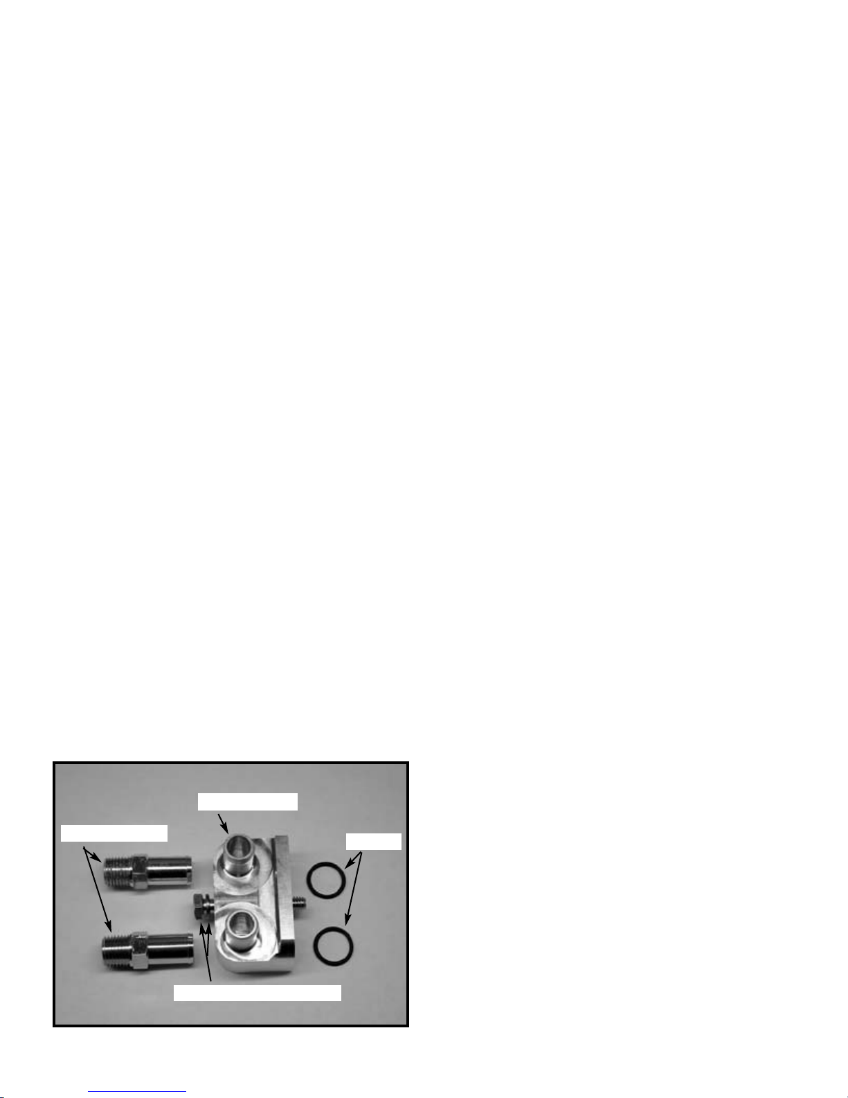
2. Oil conduit block and oil hose installation
See Picture I1
13
Conduit Block
Grade 5 bolt and washer
O-rings
Oil tank fittings
Picture I 1

NOTE - S&S oil line, oil tank fittings, and oil conduit block
fittings have a larger diameter than OEM components.
CAUTION - Do not use the existing OEM oil tank
fittings with S&S oil line #50-8157. The OEM fittings are
not large enough diameter for the S&S oil line.
NOTES:
●
lnstallations must use supplied S&S oil tank fittings
instead of the smaller diameter OEM fittings.
●
Use only the supplied oil line to connect the engine to
the transmission oil tank. The supplied oil line is higher
quality and has a higher heat rating than common oil line.
The supplied piece is long enough for both inlet and outlet
oil lines. Cut as required
●
For installations using a transmission mounted oil tank,It
is easier to connect the oil hoses between the transmission
and engine by installing the Conduit Block after the oil
hoses have been attached to the transmission.
1. After engine installation, position oil hoses as
they will be routed, and mark for length.
2. Trim hoses as required.
3. Slide all four clamps onto hoses. (Two clamps
per hose.)
4. Attach oil hoses onto installed oil tank fittings
and secure with clamps.
5. Slide both conduit block fittings into the oil
hoses
6. Seat new o-rings in grooves of oil conduit
block.
7. Secure o-rings in position with a dab of clean
grease.
8. Use 1/4"-20x2” hex head bolt to attach oil
conduit block to case. Tighten to 100 in.-lbs.
9. Secure hoses onto conduit block with clamps
CAUTION - Improper installation of oil lines or fittings
may result in parts damage not covered under
warranty.
3. Oil recommendations
NOTES:
●
S&S Cycle suggests that the engine be broken-in using
a regular petroleum-based oil. It allows the required wear
patterns to form on mating parts for proper break-in.
Experience has shown that synthetic oils will not allow new
parts to wear enough in the break in process, leading to
glazed cylinders and excessive blow-by. After the 1000
mile break-in period, synthetic oil may be used. Follow the
same viscosity range, according to ambient temperature,
as a petroleum oil.
●
Whether using synthetic or regular motor oil, S&S Cycle
recommends it be formulated specifically for 4-stroke, air
cooled motorcycle engines. Oils intended for automotive
use may not contain additives needed to meet the
demands of air cooled engines.
●
S&S Cycle recommends the use of Harley-Davidson oil
filters, part numbers 63731-99 (black), or 63798-99
(chrome),or equivalent.
4. Verify oiling system operation before starting
1. Fill the oil tank to the proper level.
2 Remove spark plugs. Ground plug wires to
cylinder head with either a jumper wire or
through a test plug.
3. Remove oil sender unit.
4. Turn ignition on and turn the engine over with
the starter motor until engine oil appears at the
oil pressure sender hole.
5. Re-install and re-connect oil sender unit.
6. Verify that engine oil is returning to oil tank.
7. Start motorcycle. Verify oil pressure by
watching oil pressure light.
14
Viscosity Ambient Temperature (º F)
SAE 20W50 Above 20º - 100º
SAE 50 Above 60º - 100º
SAE 60 Above 80º - 100º

NOTES:
●
If oil fails to appear at oil sender hole within 30 seconds
of starter operation, allow the starter to cool. verify that oil
line routing is correct and that the oil tank is full to the
proper level
●
Oil pressure indicator lamp should light when ignition is
turned on. Lamp will go out after engine is started and there
is oil pressure at the switch in the crankcase.
CAUTION - Avoid excessive time of starter
engagement. Overheating of starter motor will result in
damage. Oil pump should prime and deliver oil to the
oil sender hole within 30 seconds.
J. Exhaust System
NOTE - The engine must be correctly mounted into the
frame before the exhaust system is installed.
1. Place new woven-metal gasket into exhaust ports
of cylinder heads.
2. Inspect the exhaust pipe header flanges and
retaining rings. Replace if distorted, warped, or
otherwise damaged.
3. Apply a high-temp. anti-seize lubricant to threads
of exhaust studs at cylinder heads.
4. Install exhausts to cylinder heads. Hand tighten
exhaust stud nuts.
5. Attach exhausts to lower mounting bracket. Shim if
necessary. Hand tighten mounting hardware.
6. Tighten exhaust flange nuts at head to 60-80 in-lbs.
WARNING - In some instances, brake master cylinder
must be spaced out from frame to clear crankcase.
UNDER NO CIRCUMSTANCES SHOULD MASTER
CYLINDER OR BRAKE LINE BE ALLOWED TO
CONTACT EXHAUST PIPE IN FINAL INSTALLATION.
Heat transferred to brake fluid may expand and cause
brakes to seize, resulting in possible fire hazard and
loss of control of motorcycle with injury or death to
rider and others.
NOTE - Make certain that the exhaust system is not pre-
loaded, or in a bind, at the lower mounting points. Make all
spacing adjustments prior to final-tightening of the upper
exhaust mounting hardware at the cylinder heads. Failure
to follow this procedure may cause excessive vibration and
result in failure of exhaust pipes or mounting hardware.
K. Initial Start-Up And Engine Break-In
NOTE - engines are designed for high performance and as
such are not as tolerant of inadequate break-in as stock or
lower performance engines. Correct break-in will assure
longer engine life and will prevent unnecessary engine
damage. Engine damage caused by improper break-in is
not covered under the S&S warranty.
1. Initial start-up
1. For the initial start up, the fuel and ignition
systems should be adjusted to their baseline
settings. (Baseline settings allow the bike to
start and run, and are the starting point for
tuning.) This is adequate for the initial start-up
and heat-cycling of the engine.
NOTE - Because there are several ignition and fuel system
combinations possible with the S&S Twin Cam style
engine, baseline settings are not listed here. Refer to the
appropriate ignition or fuel system instruction sheet.
2. Run engine approximately one minute at 1250-
1750 rpm. DO NOT crack throttle or subject to
any loads during this period as head gaskets
are susceptible to failure at this time. During
this time, check to see that oil pressure is
normal, and that oil is returning the oil tank.
3. Shut off engine and thoroughly check for any
oil leaks, fuel leaks, or other problems. Let
engine cool to the touch.
4. After engine has cooled, start up again and
allow the motor to build some heat. Engine
should not be run longer than three to four
minutes. When the cylinders become warm/hot
to the touch (approximately 150°) shut the motor
down and let it cool to room temp. Follow the
same cautions as for the initial start-up, and
continue to watch for problems.
5. Repeat this procedure 3 or 4 times. Each
successive time it should take slightly longer to
warm up and you can increase the temperature
slightly each time. You can be more liberal each
time with the rpm, gently vary rpm continuously
from idle up to 2500 rpm in the final cycle. The
motor should not reach full operating
temperature during these cycles. Do not allow
engine temperature to become excessive.
15

2. Engine break-in
1. Closely monitor engine for excessive heat
build-up. Do not allow the engine to idle for
long periods of time. Be especially watchful
when air temperatures exceed 90 degrees.
Slow speed operation in urban areas during
the summertime is especially hard on engines..
Temperature for engine oil should be between
180º - 240º F. If engine oil temperature stays
above 220º F, and correct ignition timing has
been verified, S&S Cycle suggests that an oil
cooler be installed. Do not run engine under
conditions where oil temperatures continue to
remain high.
2. For the first 50 miles ride the motorcycle in a
very conservative manner. The first 50 miles
are most critical for new rings and piston
break-in. Engine damage is most likely to
occur during this period. Keep heat down by
not exceeding 2500 rpm. Avoid lugging the
motor, riding in hot weather or in traffic. Vary
the engine speed. Do not lug the engine.
Change the oil at 50 miles. This will remove the
heavy accumulation of break in residue from
the oiling system.
3. The next 500 miles should be spent running
engine no faster than 3500 rpm or 60 mph.
Correct any obvious ignition or fuel problems, if
present. Avoid continuous steady speeds, and
do not lug the engine. Vary engine rpm.
change the oil again at 500 miles.
CAUTION – Lugging or running engine prematurely at
sustained high rpm may result in damage to pistons
and other engine components. S&S voids it’s
guarantee if engine is not broken in properly.
4. For the balance of the first 1000 miles the
motor can be run in a normal but conservative
manner. You can be more liberal with the rpm
range and motorcycle can be operated at
normal highway speeds. Avoid overheating or
putting any hard strain on the engine: no drag
racing, dyno runs, excessive speed, trailer
towing or sidecar operation.
5. After 1000 miles, verify Ignition and fuel
system settings and adjustments. Change the
engine oil. The break in process is complete.
L. Tuning Guidelines
Ignition timing and carburetor jetting are responsibilities
of the customer. If not thoroughly familiar with these
procedures, contact a professional mechanic.
1. Exhaust Systems
Muffled exhaust systems.
If you have an existing 2-into-2 system that uses
slip-on style mufflers, whether it is an OEM or an
aftermarket system, we recommend the new S&S
slip-on mufflers. S&S dyno tests achieve almost 8
more horsepower and 5 ft. lbs. of torque on a stock
Twin Cam 88 engine using stock header pipes and
S&S slip-on mufflers, and S&S Super Sidewinder
engines have produced 1-1.1 horsepower per
cubic inch using stock style exhaust and S&S slip-
on mufflers. These mufflers will allow your engine
produce more horsepower and torque than
straight-through drag pipes in street and highway
driving, and work equally well on both stock and
large displacement engines.
Drag pipes
While drag pipes can be used with good results to
achieve top end horsepower, they are generally not
recommended for street applications. Carburetor
adjustment and jetting is generally easier for
engines with muffled exhaust systems.
2. Gearing
Gearing depends on the total weight of the
machine and rider, the size of the engine, cam,
exhaust system and type of riding. Most high
performance engines, and particularly those with
larger displacements, are capable of pulling more
gear. We suggest you break the engine in with
stock gearing to minimize the load on the engine.
After the engine is broken in, you will have a better
feel of its potential and can change gearing
accordingly.
The following formula will determine final drive
gear ratio:
Engine Revolutions Per One Revolution of Rear Wheel=
(Clutch Sprocket*) x (Rear Wheel Sprocket*)
(Motor Sprocket*) x (Trasmission Sprocket*)
*Number of teeth on each sprocket
16

17
Displacement Bore Stroke Compression Ratio
124” 4-1⁄8” 4-5⁄8” 10.8:1
Cylinder Heads Specification
Valve guide in head (tight) .0015”-.003”
Valve seat in head (tight) .005”-.0075”
Valves Specification Service
(Fit in guide.) Wear Limit
Intake .0012”-.0015” .0025”
Exhaust .0018”-.0023” .0035”
Seat Width .040”-.062”
Stem Protrustion 2.045”-2.060” 2.080”
Rocker Arms Specification Service
Wear Limit
Shaft fit in bushing (loose) .0007”-.0018” .0035”
Bushing fit in rocker arm (tight) .002”-.004”
Hydraulic Lifters Specification Service
Wear Limit
Lifter fit in guide (loose) .0006”-.0017” .003”
Pistons Specification Service
Wear Limit
Fit in cylinder .002”-.0025” .005”
End gaps: .017”-.025” .028”
Top two compression
Oil control rails .016”-.035” .050”
Crankcase Specification Service
Wear Limit
Timkin race in case (tight) .001”-.003” less than .0025”
Pinion race in case (tight) .001”-.003” less than .0025”
Connecting Rods Specification Service
Wear Limit
Crankpin bearing .001”-.0012” .002”
Running clearance
Piston pin fitment in rod .0005”-.001” .002”
Connecting rod side-play .015”-.035” .040”
Torque Values Specification S&S
Suggestion
Rocker box hardware 1⁄4” 120 in-lbs. Loctite 243
Rocker box hardware 5⁄16” 18 ft-lbs. Loctite 243
Tappet guide fasteners 120 in-lbs. Loctite 243
Pushrod locknuts 120 in-lbs.
Cylinder head bolts See chart on page 11.
Crankcase fasteners 1⁄4” 120 in-lbs.
Crankcase fasteners 5⁄16” 15 ft-lbs.
Gearcover fasteners 120 in-lbs. Loctite 243
Intake manifold-to-head 16 ft-lbs. Loctite 243
Intake manifold-to-carb 18 ft-lbs. Loctite 243
Exhaust flange-to-head 60-80 in-lbs. Anti-seize
Spark plug 11-18 ft-lbs. Anti-seize
Cylinder studs 10 ft-lbs. Loctite 262
Piston oiler screws 35 in.-lbs. Locktite 243
Flywheels Specification Service
Wear Limit
Runout (shaft at flywheel) .0005”-.001” .003”
End play .001”-.005” exceeds .005”
M. Engine Specifications and Torque Values
18
S&S Recommended Regular Service Intervals
Item Interval
Engine Oil & Filter ...........................................Change at 50, 500, 2,500 miles, every 2,500
........................................................................miles thereafter. 1
Air Cleaner.......................................................Inspect at 50 and 500 miles, every 2,500
........................................................................miles thereafter. 2
Petcock, Lines, & Fittings. Vacuum Lines........Inspect at 50 and 500 miles, every 2,500
........................................................................miles thereafter.
Fuel Filters ......................................................Every 5,000 miles.
Engine Idle Speed............................................Adjust as required.
Throttle & Enrichment Device Control .............Inspect and lubricate throttle cables at 500
........................................................................miles and every 2,500 miles thereafter.
Spark Plugs (Champion RA8HC or equiv.)......Inspect every 5,000 miles. Replace every
........................................................................10,000 miles or as needed.
Ignition Timing - 28 deg. total advance max....Inspect every 5,000 miles.
Engine Mounts.................................................Inspect every 500 miles and every 5,000
........................................................................miles thereafter.
External Fasteners (except cyl. head bolts) ....Re-torque at 500 miles and every 5,000
........................................................................miles thereafter.
1S&S recommends that petroleum-based oil not specifically formulated for air cooled
motorcycles should be changed every 1,000 miles.
2Replace more frequently if required or if engine is operated in a dusty environment.
N. Service Intervals
Because every industry has a leader
19
12
6
4
5
33
31
18 14 12
11
16 17
12
14
10
7
19
25
27
24
26
13
15
30 29 28 20
25
32
21 23
22
3
9
8
7
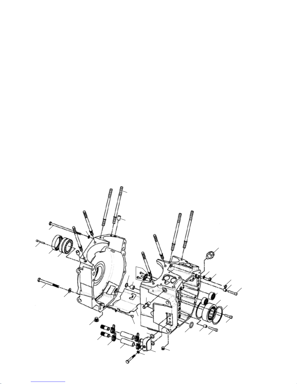
1. Bolt, stator 10-24 x1" SHC - 4 required
(HD#2720) (10 Pack)......................50-0194
2. Seal, sprocket shaft
(HD#12068) ...................................31-4035
3. Bearing, Timken (HD#9028) ..........31-4013
4. Bolt, case 5/16”" -18 x 3-1/2" HHC - 8 required
(5 Pack) ........................................50-0147
5. Washer, flat
5
⁄
16
" x
11
⁄
16
" x
1
⁄
16
" - 8 required
(10 Pack) ......................................50-7069
6. Bolt center case 1/4" -28 x 5-1/2" HHC
Grade 8 (5 Pack)....................50-0126
7. Washer, flat,
1
⁄
4
" x .474" x .050"
(10 Pack) ......................................50-7076
8. Cylinder studs - 8 required ........31-2325
9. Dowel, cylinder deck - 2 required
(HD#16595-99) (10 Pack) ................50-8179
10. Nut
1
⁄
4
"-28 Grade 8 - 1 required
(10 Pack) ......................................50-5014
11. Bolt, camplate
1
⁄
4
"-20 x 1" SHC - 4 required
(10 Pack) ......................................50-0244
12. Bolt, camplate
1
⁄
4
"-20 x 1
1
⁄
4
"SHC - 2 required
(10 Pack) ......................................50-0153
13. Oring, camplate - 7 required
(HD#11301) (10 Pack).....................50-8066
14. Dowel, camplate - 2 required
(HD#16589-99)................................50-8148
15. Bearing, inner cam (HD# 9198).....31-4080
16. Bearing, right main.
2003-up all TC
(HD#24606-00C)......................................N/A
17. Retaining ring, internal, spiraloc,
(HD#35114-02) - 2 required...............50-8160
18. Oring, oil pump
11
⁄
16
" I.D. x
15
⁄
16
" O.D. x
1
⁄
8
"
CS (HD#11293)...............................50-8039
19. Switch, oil pressure
(HD#26561-99)........................................N/A
20. Plug, sump (HD#765) ....................50-8330
21. Plug, magnetic drain ..................50-8335
22. Baffle Plate ..................................31-0119
23. Screw 10-24 -3/8" pan head - 2 required
(10 Pack)......................................50-0139
24. Dowel, case alignment - 2 required
(HD#16574-99) (10 pack) ..............50-8109
25. Oring, case alignment,
9
⁄
16
" I.D. x
11
⁄
16
" O.D. x
1
⁄
6
" CS - 2 required
(HD#26432-76A) (10 Pack) .............50-8102
26. Piston oilers - kit of 2 ..................31-2026
27. Oil line fitting- vent
(HD# 26314-99)..............................50-8147
28. Oil conduit block .........................31-2076
29. Washer, flat
1
⁄
4
" chrome
(10 Pack).....................................50-7013
30. Bolt,
1
⁄
4
"-20 x 2" HHC - 1 required
....................................................50-0303
31. Hose, oil, inlet/outlet....................50-8157
32. Spring clips - 4 required..............50-8156
33. Oil line fittings, inlet/outlet
2 required ...................................50-8158
O. Replacement Engine Assembly Parts
Use the line drawings to identify replacement parts. Parts designed to fit as direct stock replacements are listed with
corresponding H-D part number. If no H-D part number is shown, S&S part cannot be used in stock application and vice versa
Parts not shown in this diagram, are detailed by other instruction sheets accompanying the Engine.

Because every industry has a leader
This manual suits for next models
1
Table of contents
Other S&S Cycle Engine manuals


Popular Engine manuals by other brands


Aerotech
Aerotech RMS 98/10240 BLACK MAX Assembly and operation instructions

Briggs & Stratton
Briggs & Stratton 90000 series Operator's manual

Garelli
Garelli 49cc Service manual

Rockwell Automation
Rockwell Automation Allen-Bradley TLP-SSN-F046 installation instructions

Automation Technology
Automation Technology iSV2-CAN Series user manual

Briggs & Stratton
Briggs & Stratton Vanguard 130000 Operator's manual