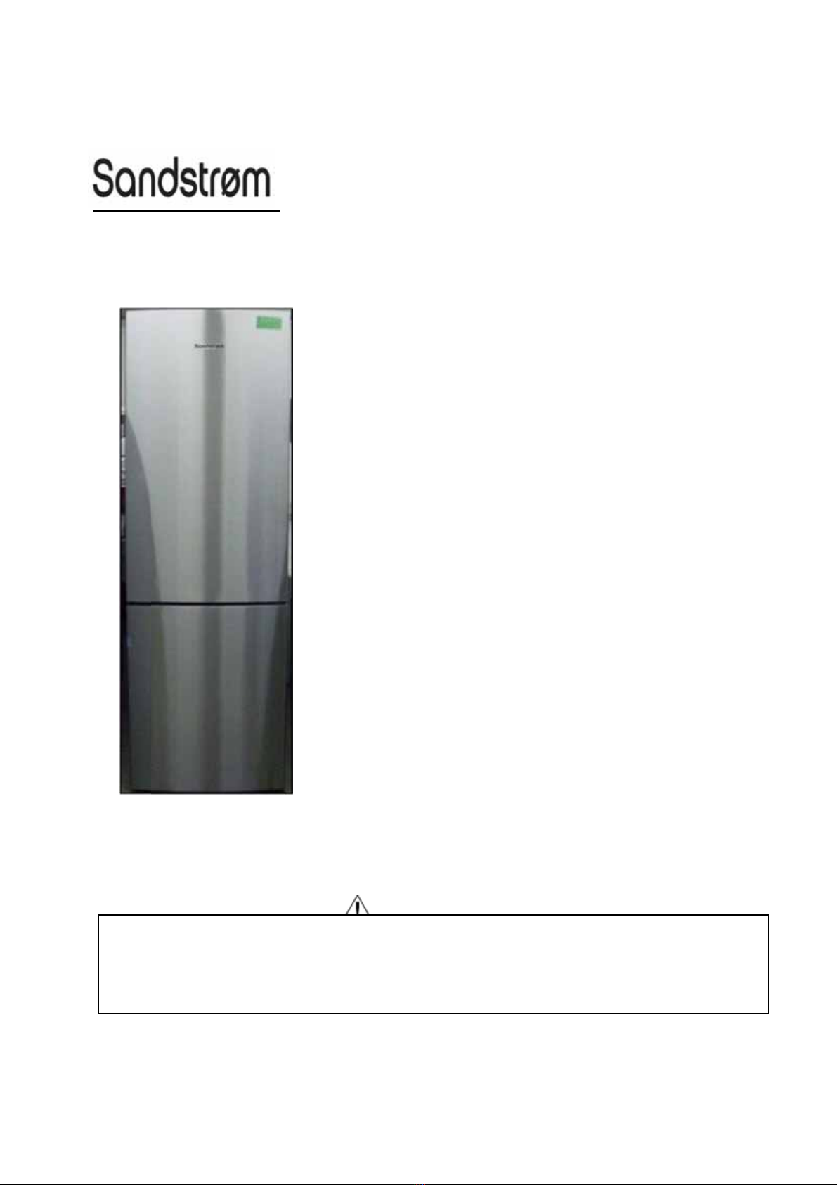
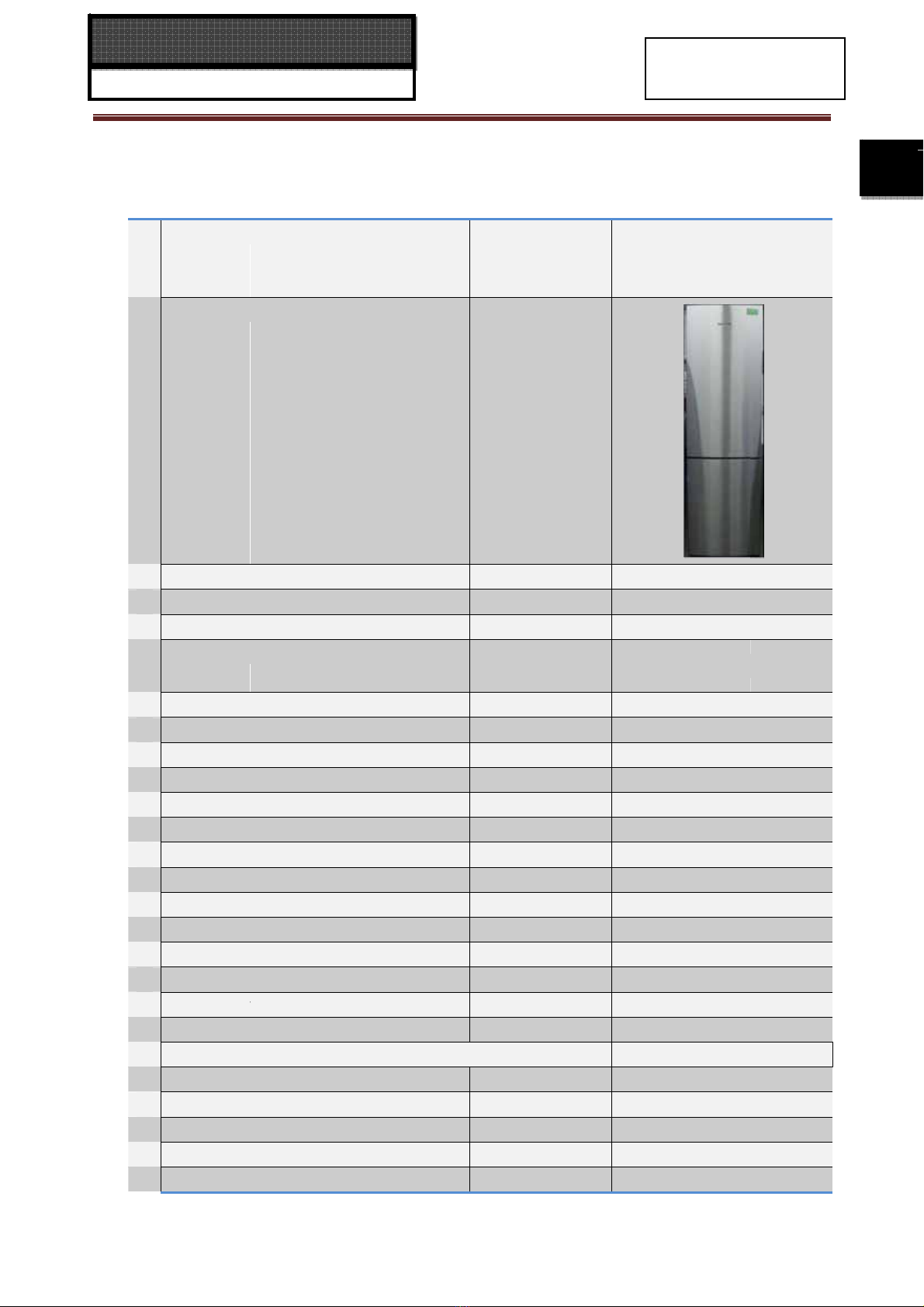
Sandstrom ssc3st12 User manual

This ser
v
dose no
t
Product
or repai
r
All
v
ice informatio
n
t
contain warni
n
powered by el
e
r
the product or
◎20
1
right reserve
d
S
n
is designed f
o
n
gs and caution
e
ctricity should
b
products dealt
w
1
2(HAIER EL
E
d
. Unauthoriz
e
S
E
R
o
r experienced
s to advice non
b
y serviced or r
e
w
ith in this serv
E
CTRICAL A
P
e
d copying a
n
R
V
I
M
O
repair technici
a
n
-technical indiv
e
paired only by
ice information
WAR
N
P
PLIANCES
C
d distribution
I
C
E
O
DE
L
a
ns only and is
iduals of poten
t
experienced p
r
by anyone els
e
N
ING
Order N
o
C
OR. LTD)
is a violation
o
Re
f
E
M
A
L
:SS
C
not designed f
o
t
ial dangers in
a
r
ofessional tech
could result in
o
.
Ref1009S
0
o
f la
w
。
f
rige
r
A
N
C
3ST
1
o
r use by the g
a
ttempting to s
e
h
nicians. Any at
t
serious injury
o
0
21V0
r
ator
U
A
1
2
eneral public. I
t
e
rvice a product
t
empt to servic
e
o
r death.
A
L
t
.
e

2
SERVICE MANUAL
Model: SSC3ST12
2
Issue 2012-05-12
Rev. Ref1009S021V0
Contents
Table of Contents ·········································································································· 2
1. General Information·································································································· 4
1-1. General guideline ······························································································· 4
1-2. Insurance test····································································································· 4
1-3. How to read this Service Manual········································································ 5
2. Product Feature ········································································································ 6
2-1. Specifications ····································································································· 6
2-2. Main Functions and Features············································································· 8
2-3. External views ···································································································· 9
2-4. Product Dimensions ··························································································· 9
3. Disassembly············································································································ 10
3-1. Installing and Removing Door ············································································ 10
3-1-1. Dismantle and install the front decoration·············································· 10
3-1-2. Dismantles and install the upper decoration strip and cables ················ 11
3-1-3. Dismantle and install the middle and lower hinge ·································· 12
3-2. Removing the Air-Duct ······················································································· 13
3-2-1. Removal of fridge air-duct·········································································· 13
3-2-2. Removal of freezing air-duct······································································ 14
4. Control and display system ····················································································· 14
4-1. Control and display panel··················································································· 14
4-2. Error code display and sensor positions·····························································18
4-2-1. Sensor location description········································································ 18
4-2-2. Graphic display of the sensor location······················································· 19
4-3. Self test model···································································································· 19
5. Control principle of electronic component ···························································· 20
5-1. Air Escaper········································································································· 20
5-2. Control Principle of the Fan motor······································································ 20
5-3. Defrost control principle······················································································ 20

3
SERVICE MANUAL
Model: SSC3ST12
3
Issue 2012-05-12
Rev. Ref1009S021V0
6. System flow principle······························································································· 21
6-1. Refrigeration flow chart····················································································· 21
6-2. Perspective of the Refrigeration System ·························································· 22
6-3. Air flow scenograph ·························································································· 23
7. Circuit diagram·········································································································· 24
7-1. Main Control PCB diagram ··············································································· 24
7-2. Main Control PCB connections········································································· 25
8. Trouble shooting······································································································· 26
8-1. Common problems and solutions ····································································· 26
8-1-1. food in the fridge storage compartment is frozen····································· 26
8-1-2. the buzzer beeps to alarm········································································ 26
8-1-3. No defrosting···························································································· 26
8-1-4. Neither displaying nor starting when powering on ··································· 27
8-1-5. Poor freezing effect accompanied by loud noise ····································· 27
8-2. Examination and Solutions for Other Problems················································ 28
8-3. Checking flow chart ·························································································· 30

4
SERVICE MANUAL
Model: SSC3ST12
4
Issue 2012-05-12
Rev. Ref1009S021V0
Chapter 1 General Information
1-1. General Guidelines
When servicing, observe the original lead dress. If a short circuit is found, replace all parts which
have been overheated or damaged by the short circuit. After servicing, see to it that all the protective
devices such as insulation barriers, insulation papers shields are properly installed. After servicing,
make the following leakage current checks to prevent the customer from being exposed to shock
hazards.
1) Leakage Current Cold Check
2) Leakage Current Hot Check
3) Prevention of Electro Static Discharge (ESD) to Electrostatic Sensitive
1-2. Insurance test
1. Check if there is any leak of current.
2. Cut out the power supply before the repair to avoid an electrical shock hazard.
3. In the case of a live-line test, insulating gloves should be worn to avoid potential electrical shock.
4. Confirm the rated current, voltage and capacity before testing with any kinds of instruments.
5. Watch if the upper door is open when you check something at a lower position.
6. Take out every part in the cabinet before moving the machine, especially things like panels (e.g. glass
shelf).
7. Please wear intact cotton gloves when repair any parts of the evaporator, so that scratches by the
sharp fins can be avoided.
8. If there is a breakdown with the refrigeration system, please surrender the machine to the service
center, else the leaked refrigerant may pollute the atmosphere.
9. The refrigerator use AC of 220V with a frequency of 50Hz.
10. A big fluctuation of voltage (exceed the range 187~230V) may cause a start failure of the refrigerator,
a burn-out of the control panel and compressor, or an abnormal sound from the compressor in
operation. In this condition an automatic voltage regulator over 60W should be added.
11. Take care not to damage the supply line. Don’t yank at the line; pull the plug out gently from the
receptacle. Don’t press the line under the cabinet or step on it. Take care not to roll on or damage the
supply line when moves the machine from the wall.
12. In the case of leakage of inflammable gases like carbon monoxide, open the door and windows. Don’t
pull out or insert the plugs of the appliance.
13. Don’t touch the refrigeration surface of the freezing compartment when the refrigerator is in operation,
especially when your hand is wet, else you may be glued to the surface.
14. Pull out the plug of power supply during clearance or power outage. Wait at least five minutes to
resume the power supply in order to prevent damage to the compressor caused by continuous restart.

SE
RV
Model:
P
h
The illust
r
may diffe
r
1-3. H
o
1-3-1. U
s
The mea
n
Note:
A
“note”
reader, s
u
Caution
:
A
“cauti
o
loose dat
a
Warnin
g
A
“warni
n
Referen
c
A
“refere
n
informati
o
RV
ICE
M
SSC3ST1
2
h
oto used
i
r
ation and
p
r
from your
o
w to rea
s
ing Icons
n
ing of eac
h
provides i
u
ch as tips
a
:
o
n” is used
a
, get an u
n
g
:
ng” is used
c
e:
n
ce” guide
s
o
n on a spe
M
AN
U
2
i
n this ma
n
p
hotos use
d
products i
n
d this S
e
h
icon is de
s
nformation
a
nd tricks.
when ther
e
n
expected
r
when ther
e
s
to other
p
cific topic.
U
AL
n
ual
d
in this M
a
n
some way
.
e
rvice M
a
s
cribed in t
h
that is not
e
is danger,
r
esult or ha
s
e
is danger
p
laces in th
5
a
nual may
n
.
a
nual
h
e table be
indispens
a
through in
s
to restart
of persona
l
is binder o
n
ot base o
n
low:
a
ble, but m
correct ma
n
(part of) a
p
l
injury.
r in this m
a
I
s
R
n
the final d
a
y neverth
e
n
ipulation,
m
p
rocedure.
a
nual, whe
r
s
sue 2012-
0
R
ev. Ref10
0
d
esign of pr
e
less be v
a
m
ay dama
g
r
e we will
f
0
5-12
0
9S021V0
o
ducts, wh
i
a
luable to
t
g
e equipm
e
f
ind additio
n
5
i
ch
t
he
e
nt,
n
al

SE
RV
Model:
Chap
t
2-1. SP
1
2
3
RV
ICE
M
SSC3ST1
2
t
er 2 P
P
ECIFIC
A
Model
s
Sketch
Product descr
i
T
y
pe of applia
n
Type of coolin
g
Climate class*
Freezer comp
a
Ke
y
featur
e
Gross capacit
y
Total net capa
c
Net capacit
y
r
e
Net capacit
y
f
r
Freezin
g
capa
Ener
gy
consu
m
Max stora
g
e ti
Defrostin
g
Frost free s
y
s
t
Defrost water
o
A
ir circulatin
g
v
Kind of coolan
Technical dat
Volta
g
e / frequ
Input power /
m
Temperature r
a
Refrigerator
Chiller / Meat
C
M
AN
U
2
roduc
t
A
TIONS
s
i
ption
(
Refri
ge
n
ce
(
FS= frees
t
g
s
y
stem
(
NF=
n
a
rtment / Star r
a
e
s
y
c
it
y
e
fri
g
erator com
r
eezer compart
m
cit
y
m
ption /
y
ear
me at breakdo
w
(
M=manu
a
t
em
o
utlet
v
entilator
t
(R
a
enc
y
m
ains fuse mini
a
n
g
e
(
from>to
)
C
risper
U
AL
t
Feat
u
e
rator/Freezer
)
t
andin
g
/BI= bui
n
o frost/ S=stati
c
a
tin
g
partment
m
ent /ice com
p
w
n Freezer
a
l A=autom
a
R
134a/R600a)
mum
6
u
re
i
lt-in)
c
)
p
artment
a
tic
)
L
L
L
L
kg
kWh
Min
V/Hz
W /A
°C
I
s
R
s
sue 2012-
0
R
ev. Ref10
0
SSC3ST
1
Refri
g
erat
o
FS
NF
SN-T
4*
372
340
260
80/80
11kg
328
16
A
yes
yes
yes
R600a/ 55
g
220-240~/
5
100/
(
DC
)
1-8°C
- / 3-10°C
0
5-12
0
9S021V0
1
2
or
g
5
0
6

7
SERVICE MANUAL
Model: SSC3ST12
7
Issue 2012-05-12
Rev. Ref1009S021V0
Vegetable Crisper 0-10°C
Freezer -16 ~-25°C
Features:
Cooling system: K=Compressor /
A=Absorption K
Max noise level dB(A) 42
4 Aesthetics
Colors: W=white G=silver gray
B=Obsidian SS=stainless steel
W
Fascia panel / Handle (w / c) w/w
F= flat / R= rounded / S= streamline R
Inside colour w
Compartments number n° 2
Bottle compartment n° 4
Hinged (r =right l =left) / reversible r / X
Shelves:
Number Fridge / Freezer
4 / -
Type (gr=grill / g=glass / p=plastic)
g / -
Color w-white / b=blue / t=transparent.
t
Adjustable (Y=yes / N=not)
yes
Foldable Shelf No
Bottle Rack No
Drawers:
Plastic drawers (fully freezing comp.) n°. 2
Half freezing comp n°. 1
Colour of drawer (w=white/t=transp./g=green) t
Crisper:
Chiller / Meat (salad crisper) transparent / white Chiller (t)
Vegetable crisper(s) transparent / white t
5 Equipment & accessories
Control panel
Interior / exterior Interior
Thermometer interior / exterior Interior
Display type LED
Control lamps green / yellow /white yellow
O
ver temperature alarm LED / acoustic acoustic
Adjustable thermostat yes
Fast freeze switch /-function yes
Deodorizing No
Interior light W x
LED light n° Half
Freeze pack(s) n° 3

8
SERVICE MANUAL
Model: SSC3ST12
8
Issue 2012-05-12
Rev. Ref1009S021V0
ice maker Manual/Automatic M
Ice cube tray(s) n° 1
Butter holder yes
Egg trays 2
Adjustable feet front / rear n° 2 / -
Length of cable/incl. plug cm 200
Condenser Back wall / Integrated B
6 Product dimensions
Unit dimensions ( H / W / D) cm 200/60/67
Depth Without handle cm 67
D
epth with open door cm 1188
Door open angle n° <135
Net weight kg 86
7 Packing dimensions & load ability
Packing dimensions (H / W / D) cm 206.7/66.4/73
Gross weight kg 86
40 ' Container load pcs 54
40 ' HC Container load pcs 72
8 Recycling symbols
Packing materials / Recycling symbols (RS) RS RS
Carton weight in gr 6270
Polystyrene weight in gr 06 2570
Polyethylene foil weight in gr 04 210
9 Service
Users instruction (languages) D / F / I / GB / E / P / NL
2-2 Main Functions and Features
◆Energy saving and convenience (only in some models).
◆Half-shelf structure.
◆Innovative long-efficiency lighting system.
◆Foldaway wine holder.
◆Large crisper with humidity adjustment.
◆Holiday function.
◆Power ON/OFF function is set on the display panel (only in some models).
◆Fridge storage compartment can be set on/off separately.
◆Intelligent alarm function: automatic alarm at over temperature, malfunction, door open.
◆Touch keys (only in some models).
◆Deodorizer (only in some models).
◆Zero degree fresh keeping.
2-3. External views

SE
RV
Model:
2-4. Pr
o
Two-Door
Refrigerat
Refrigerat
Refrigerat
Cabinet d
e
Door dept
RV
ICE
M
SSC3ST1
2
o
duct Di
m
Refrigerat
o
t
or height H
=
t
or width W
=
t
or depth D
=
e
pth D1=57
t
h D2=78m
m
M
AN
U
2
m
ensio
n
o
r Dimensio
n
=
2000mm
=
595mm
=
670mm
6mm
m
U
AL
n
s
n
s:
9
I
s
R
s
sue 2012-
0
R
ev. Ref10
0
0
5-12
0
9S021V0
9

SE
RV
Model:
Chap
t
3-1 In
Pre
c
(1) Befor
e
unplug
(2) Durin
g
proper
t
(3) While l
forwar
d
3-1-1 Dis
PART-1
⑴Pull
d
⑵Deta
c
⑶Lift t
h
conn
e
of th
e
⑷Deta
c
⑸Turn
o
table
-
⑹Secu
r
⑺Instal
exch
a
Note
from
t
RV
ICE
M
SSC3ST1
2
t
er 3
D
stalling
c
autions
D
e
removing
the refriger
g
dismantli
n
t
y loss, at le
l
ifting the hi
n
d
.
mantle an
d
Befor
e
d
ecoration c
o
c
h the 2 scr
e
h
e front dec
o
e
cting it. Pl
e
e
refrigerato
r
c
h the scre
w
o
ver the up
p
-
board in th
e
r
e the 2 scr
e
l the 2 dec
o
a
nged.
: for the m
o
t
he one sho
Front
Scr
e
M
AN
U
2
D
isass
e
and Re
m
D
uring Di
s
the doors,
p
ator power
c
n
g of the d
o
ast two adu
n
ges to sep
a
d
install fr
o
e
change
o
vers 1 and
e
ws fixing t
h
o
ration strip
e
ase do not
r
.
w
s affixed to
p
er hinge a
n
e
reversed
d
e
ws on the
t
o
ration cove
o
dels with c
a
wn in the fi
g
decoration st
r
ew
Cove
r
U
AL
e
mbly
m
oving
D
s
mantling
p
lease rem
o
c
ord to avoi
d
o
or, in orde
lts are nee
d
a
rate it from
o
nt decora
t
2 downwa
r
h
e front dec
o
of the tabl
e
disconnect
the upper
h
n
d fix it on t
h
d
irection.
t
op.
rs on the fr
o
a
binet displ
a
g
ure. The di
s
r
ip of the tabl
e
Upp
e
S
c
r
1
10
D
oor
and Inst
a
o
ve food fr
o
d
personal i
r to avoid
p
d
ed to perfo
r
the door, pl
e
t
ion strip
o
r
d to remov
e
o
ration strip
e
-board out
w
the wires.
G
h
inge and r
e
h
e other sid
e
o
nt decorati
o
a
y, the front
s
mantling a
n
e
-board
e
r hinge
Cover 2
c
re
w
a
llation of
o
m the shel
njury, produ
p
ossible pe
r
m the follo
w
e
ase take c
a
o
f the table
e
them and
r
of the table
w
ard and up
G
ently put t
h
e
move the h
i
e
. Then, ins
t
o
n strip of t
h
decoration
s
n
d installati
o
I
s
R
The Door
v
es and th
e
ct damage
o
r
sonal injur
y
w
ing operati
o
a
re to preve
-
board an
d
After c
h
r
etain.
-
board.
w
ard. At thi
s
h
e front dec
o
nge.
t
all the front
h
e table-bo
a
s
trip of the
t
o
n methods
s
sue 2012-
0
R
ev. Ref10
0
r
e
bottle gu
a
o
r property
l
y
, product
d
o
ns.
e
nt the door
f
d
the uppe
r
h
ange
s time, ther
e
o
ration strip
t
decoration
a
rd with the
t
able-board
are the sa
m
0
5-12
0
9S021V0
a
rds. Then,
l
oss.
d
amage or
f
rom falling
r
hinge
e
are wires
on the top
strip of the
ir positions
is different
m
e.
10

Up
p
Cable
s
SE
RV
Model:
3-1-2 Dis
PART-2
(1) Remo
(2) Remo
the p
o
pullin
g
away
f
(3) Disco
n
hinge
(4) Loos
e
refrig
e
(5) Pull t
h
upper
(6) Remo
after t
u
(7) Turn t
h
(8) Hang
toget
h
for th
e
(9) Tuck
t
decor
a
(10) Turn
t
p
er hinge
s
in cabin
et
Co
n
RV
ICE
M
SSC3ST1
2
mantle an
d
Bef
o
ve the dec
o
ve the upp
e
o
sition show
g
the decor
a
f
rom the do
o
n
nect the c
o
conduit res
p
e
n the scre
w
e
rating com
p
h
e axis from
hinge by pl
a
ve the stop
u
rning 180
d
h
e middle h
the door o
n
h
er. Tuck th
e
e
cabinet int
o
t
he connect
e
a
tion strip o
n
t
he decorati
n
nector
Cables for
t
M
AN
U
2
d
install th
e
o
re change
o
ration cove
r
e
r decoratio
n
n by the arr
o
a
tion strip u
p
o
r. The ope
r
o
nnectors a
n
p
ectively.
w
s affixed
p
artment do
o
the upper
h
a
cing the a
x
block on th
d
egrees.
inge by 180
n
the middl
e
e
cables for
o
the upper
e
d connect
o
n
the door.
on piece by
U
p
t
he doors
U
AL
e
upper de
r
s from the
d
n
strip from t
o
w and ligh
t
p
ward with
a
r
ation meth
o
n
d pull out t
h
t
o the upp
e
o
r can be lif
t
h
inge. Then,
x
is into the
d
e
bottom of
degrees a
n
e
hinge and
t
he door int
o
hinge cond
u
o
rs into the
c
180 degre
e
p
per decorati
o
Dec
Upper hinge
11
e
coration s
t
d
oor and re
t
t
he door. In
s
t
ly pull the
s
a
nother ha
n
o
ds on the r
i
h
e cables i
n
e
r hinge to
f
ted up and
s
,
insert it fro
d
oor axis ho
the door a
n
n
d then fit it
o
secure the
o
the condu
u
it.
conduit on
t
e
s and inser
t
o
n strip
c
oration cover
axis
t
rip and c
a
t
ain.
s
ert a “-”scr
e
s
crewdriver
h
n
d. In this w
a
i
ght side an
d
n
the door c
o
remove t
h
s
eparated f
r
m the other
l
e after turn
i
n
d then rea
t
o
n the othe
r
hinge’s scr
e
it on the ot
h
t
he upper d
e
t
it between
I
s
R
a
bles
After c
h
e
wdriver into
h
andle in th
e
a
y the dec
o
d
the left si
d
o
nduit and t
h
h
e hinge. A
r
om the mid
d
end of the
u
ng 180 deg
r
acht on the
r
side of the
e
ws. Conn
e
h
er side of t
h
e
coration st
the door an
d
s
sue 2012-
0
R
ev. Ref10
0
h
ange
o
the decora
t
e
arrow dir
e
o
ration strip
d
e are the s
a
he cables i
n
A
t the sam
e
d
le hinge.
u
pper hinge
rees.
other side
o
cabinet.
e
ct the two
c
h
e door and
t
rip and join
t
d
the upper
Con
n
0
5-12
0
9S021V0
t
ion strip at
e
ction while
will detach
a
me.
n
the upper
e
time, the
. Insert the
o
f the door
c
onnectors
the cables
t
the upper
decoration
ector
Cables in c
a
11
a
binet

SE
RV
Model:
strip
a
Note
3-1-3: Di
s
PART-3
(1) Deta
c
and t
h
(2) Rem
o
door
s
(3) Tilt th
hing
e
(4) Fix t
h
the l
o
(5) Take
Turn
t
scre
w
origi
n
Hole pl
u
RV
ICE
M
SSC3ST1
2
a
t the other
s
: for the mo
d
s
mantle a
n
Bef
o
c
h the 3 sc
r
h
en screw i
t
o
ve the upp
s
. Turn them
e refrigerat
o
e
.
h
e lower hin
g
o
wer hinge.
out the 3 h
o
t
he middle
h
w
s removed
n
ally.
u
g
S
M
AN
U
2
s
ide of the c
d
els with c
a
n
d install t
h
o
re change
r
ews affixed
t
from the r
e
er and low
e
by 180 de
g
o
r to the req
u
g
e to the b
o
o
le plugs on
h
inge by 18
0
in step 1.
crews affixed
U
AL
abinet.
a
binet displa
y
h
e middle
a
to the mid
d
versed dire
c
e
r doors se
p
g
rees and r
e
u
ired angle.
o
ttom of the
the other si
0
degrees
a
Mount the
Middle hinge
Sc
r
Middl
e
to the lower
h
lower
12
y, the abov
e
a
nd lower
h
d
le hinge a
n
c
tion.
p
arately. Di
s
e
fit them on
t
Detach the
other side
o
de of the c
a
a
nd install it
3 hole plu
g
r
ews
e
hinge axis
h
inge
hinge
e
operation
c
h
inges
n
d remove t
h
s
mantle the
t
he other si
d
screws fixi
n
o
f the cabin
e
a
binet.
on the oth
e
g
s into the
I
s
R
c
oncerning
c
After c
h
h
e hinge. U
stop block
s
d
e.
n
g the lower
e
t. Then, m
o
e
r side of th
e
holes wher
e
s
sue 2012-
0
R
ev. Ref10
0
c
ables is n
o
h
ange
nscrew the
s
on the bo
t
r
hinge and
r
o
unt the lo
w
e
cabinet.
A
e
the hing
e
0
5-12
0
9S021V0
o
t needed.
hinge axis
t
tom of the
r
emove the
w
er door on
A
ttach the 3
e
is seated
12

SE
RV
Model:
3-2 Re
m
3-2-1 R
e
①
(1) Take
o
of the
a
(2) Detac
h
(3) Tilt th
e
on its l
o
3-2-2 R
e
(1) Ta
k
rem
3-d
o
(2) De
t
(3) Re
m
the
(4) Pul
(5) De
t
(6) Tilt
(7) Ta
k
RV
ICE
M
SSC3ST1
2
m
oving
t
e
moval of
f
o
ut the acc
e
a
i
r
-duct (inc
l
h
the 2 scre
w
e
refrigerati
o
o
wer side.
P
e
moval of
f
①
⑤
k
e out the
a
oval of the
f
o
or models)
t
ach the scr
e
m
ove the h
a
harness co
v
l out the wir
e
t
ach the 2 s
c
the freezin
g
k
e out the fr
e
M
AN
U
2
t
he Air-
D
f
ridge air
-
②
e
ssories in t
h
l
uding shel
v
w
s in the u
p
o
n ai
r
-duct f
o
P
ull out the
c
f
reezing
a
⑥
a
ccessories
f
reezing ai
r
-
(fig ①);
e
w in the h
a
a
rness cove
v
er to facilit
a
e
s under th
e
c
rews in th
e
g
ai
r
-duct fo
r
e
ezing ai
r
-d
u
U
AL
uct
-
duct
h
e fridge st
o
es, large a
n
p
per part of
t
o
rward entir
e
c
onnector a
n
a
ir-duct
②
⑥
in the fre
e
duct (draw
e
a
rness cove
r
r. There is
a
a
te the rem
o
e
harness c
o
e
freezing ai
r
r
ward from t
u
ct and the
f
13
③
o
rage comp
a
n
d small cris
t
he ai
r
-duct
r
ely around
i
n
d you can
r
e
zer storag
e
e
rs of 2-doo
r
r
over the fr
e
a
small inde
n
o
val (fig ③)
;
o
ver and pu
r
-duct onto
t
t
op to botto
m
f
in evapora
t
④
a
rtment whi
pers, ai
r
-du
c
(fig. ②);
i
ts upper si
d
r
emove the
③
⑦
e
compartm
e
r
models, m
i
e
ezing ai
r
-d
n
tation on
b
;
ll out the c
o
t
he freezer
c
m
and you c
t
or is just b
e
I
s
R
④
ch may int
e
c
t decoratio
d
e until you
c
refrigeratio
n
e
nt which
m
ddle/botto
m
u
ct; (fig ②)
;
oth upper s
i
nnector (fig
c
hamber (fi
g
a
n remove
t
hind it (fig
⑦
s
sue 2012-
0
R
ev. Ref10
0
⑤
e
rfere with t
h
n strips) (fi
g
can see th
e
n
ai
r
-duct (fi
g
④
m
ay interfe
r
m
doors and
;
ide and bot
t
④);
g
⑤);
t
he ai
r
-duct
⑦
).
0
5-12
0
9S021V0
h
e removal
g
. ①);
e
connector
g
. ③④⑤);
④
r
e with the
drawers of
t
om side of
(fig ⑥);
13

SE
RV
Model:
W
h
air
-
Chap
t
4-1. Co
Model:
S
Control
Fridge st
o
A1 Switc
h
A3 Suppe
r
A5 Fridge
A7 Freeze
A9 Over-t
e
■ Initial
When th
e
compartm
temperat
u
inside. T
h
decrease
s
freezer st
o
■ Fridg
e
Press ke
y
RV
ICE
M
SSC3ST1
2
h
en reinstall
-
duct.
t
er 4
C
ntrol and
S
SC3ST1
2
panel
o
rage comp
a
h
on/off the
f
r
cool
temperature
r temperatur
e
e
mperature/
d
powering o
e
refrigerato
m
ent indicat
o
u
re inside. T
h
e buzzer
w
s
to certain
o
rage comp
a
e
storage t
e
y
A4 or A5 t
o
M
AN
U
2
ing, please
C
ontrol
display
p
2
a
rtment tem
p
f
ridge storag
e
down
e
down
d
oor open ala
r
n
r is power
e
o
r will light.
T
he freezer
s
w
ill beep. Pr
e
level, the
d
a
rtment will
e
mperature
s
o
set the fri
d
U
AL
connect t
h
and d
i
p
anel
p
erature
e
compartme
n
rm
e
d on for th
T
he fridge st
s
torage tem
p
e
ss key A9
,
d
isplayed t
e
become th
e
s
etup
d
ge storage
14
h
e connect
o
i
splay
Freeze
r
n
t A2
H
A4
F
A6
F
A8
A10
P
e first time
,
t
orage temp
e
p
erature wil
, and the b
u
e
mperature
s
e
ex-factory
temperatur
e
o
r first and
syste
m
r
storage co
m
H
oliday fun
c
F
ridge temp
e
F
reezer tem
p
S
upper freez
e
P
ower ON/
O
,
the powe
r
e
rature will
b
l be display
e
u
zzer will b
s
of the frid
g
settings “5”
e
. The fridg
e
I
s
R
then moun
t
m
m
partment
t
tion
e
rature up
erature up
e
FF
r
indicator
a
b
e displaye
d
e
d as“- -” d
u
e
silenced.
g
e storage
and “-18” r
e
e
storage te
m
s
sue 2012-
0
R
ev. Ref10
0
t and fix t
h
t
emperatur
e
a
nd the frid
g
d
as “-” due
u
e to high t
e
After the t
e
compartme
e
spectively.
mperature
c
0
5-12
0
9S021V0
h
e freezing
e
g
e storage
to the high
e
mperature
e
mperature
nt and the
c
ycles from
14

15
SERVICE MANUAL
Model: SSC3ST12
15
Issue 2012-05-12
Rev. Ref1009S021V0
1 to 8. The setting is confirmed automatically 5 seconds after the operation is finished or by pressing
any other key.
■ Freezing storage temperature setup
Press key A6 or A7 to set the freezer storage temperature. The freezer storage temperature cycles
from -14 to -26℃. It will be confirmed automatically 5 seconds after the operation is finished or by
pressing any other key.
■ Super cooling
Select this function after you have put fresh food in the fridge storage compartment. Press key A3, and
this function is activated and the corresponding indicator illuminates. This function will automatically
deactivate when the temperature decreases to the required level. You can also deactivate it by
pressing key A3 again.
■ Super freezing
Select this function after you have put large amount of food in the freezer storage compartment. Press
key A8, this function is activated and the corresponding indicator illuminates. This function will become
inactive automatically after 24 hours. You can also deactivate it by pressing key A8 again.
■ Holiday function
Press key A2, corresponding indicator illuminates and the holiday function of the fridge storage
compartment is activated. It will operate at a relatively high temperature in Holiday mode. The fridge
storage temperature will be indicated as “-” (Please take out the fresh food in the refrigerator and close
the door before activating this function). Press key A2 again, and the corresponding indicator goes off
and the refrigerator comes into normal control.
■ Display control
The display screen will turn off automatically 1 minute after an operation is finished. It can be lit up by
opening the door or pressing any key. (Alarm does not light up the display screen)
■ Door open alarming
When the refrigerator door is open for more than 3 minutes, the alarm indicator will flash and the
buzzer will sound 3 beeps every 30 seconds. The buzzer can be silenced by closing the door or
pressing key A9.
■ Over temperature alarm
When the temperature in the freezer storage compartment rises to a certain value, the alarm indicator
will illuminate solid and the buzzer will sound 1 beep every second. The buzzer can be silenced when
the temperature in the freezer storage compartment drops to a specified level or key A9 is pressed.
■ Turning off the fridge storage compartment
Press and hold key A1 for 3 seconds, and the corresponding indicator will turn off and the fridge
storage compartment will be turned off while the freezer storage compartment operates normally. The
fridge storage temperature indication icon will also go off. Press and hold key A1 for 3 seconds again,
the corresponding indicator will illuminate, the fridge storage compartment will be turned on, and the
fridge storage temperature indication icon will recover.

16
SERVICE MANUAL
Model: SSC3ST12
16
Issue 2012-05-12
Rev. Ref1009S021V0
■ Turning off the refrigerator
Press and hold key A10 for 3 seconds, corresponding indicator will go off, the display panel will go off
and the refrigerator will stop operating.
Press and hold key A10 for 3 seconds again, corresponding indicator will light up, the display panel will
light up, and the refrigerator will start operating normally.
This function is not equivalent to turning off the power.
■ Fault indication
When E or F is displayed due to fault, the refrigerator can still refrigerate. Please contact professional
after-sales service personnel as soon as possible.
4-2 Error code display and sensor positions
4-2-1 Sensor location description
Malfunction description Sign Display Display position Sensor location
Malfunction of the ambient
temperature sensor
H SNR F2 Display panel The ambient temperature sensor is
located on the display panel
Malfunction of the fridge
storage temperature sensor
R SNR F3 Display panel The fridge storage temperature
sensor is located on the right side
of the fridge storage compartment
Malfunction of the freezer
storage temperature sensor
F SNR F4 Display panel The freezer storage temperature
sensor is located on the left side of
the freezing air-duct cover
Malfunction of the defrosting
temperature sensor
D SNR F6 Display panel The defrosting temperature sensor
is located on the fin evaporator
Malfunction of
communication between the
display panel and the power
board
/ E0 Display panel /
Malfunction of the fan / E1 Display panel /
4-2-2 Graphic display of the sensor location

SE
RV
Model:
4-3. Se
l
TEST1:
P
p
a
o
p
T
h
TEST2:
P
a
c
s
e
D
E
s
e
th
e
di
s
tu
r
of
RV
ICE
M
SSC3ST1
2
lf test m
o
P
ress the T
E
a
nel display
s
p
erates nor
m
h
is can be u
s
P
ress TEST
c
t dependin
g
e
nsed by t
h
E
FROSTIN
G
e
nsor is bel
o
e
sensor r
e
s
plays T2
T
r
ned off, an
d
the defrosti
n
M
AN
U
2
o
del
E
ST key on
s
T1 T1 a
n
m
ally, the fa
n
s
ed to test t
h
key again i
g
on the te
m
h
e defrostin
G
MODE)a
f
o
w 10 , th
e
℃
e
aches 7℃
T
2, the refri
g
d
the defros
t
n
g heating
w
U
AL
the power
b
n
d the refri
g
n
runs at hi
g
h
e refrigera
t
n
TEST1 M
O
m
perature
s
g sensor i
s
f
ter 20s’ he
e
heating wi
In the (F
O
g
erator con
d
t
ing heating
w
ire and it s
17
b
oard to ent
g
erator ent
e
g
h speed, a
n
t
ion perfor
m
O
DE to ent
e
s
ensed by
t
s
over 10
℃
e
ating Whe
n
re will heat
O
RCED DE
d
ucts force
d
wire is turn
hould be 1
5
e
r the (PUL
e
rs forced r
e
n
d the defro
m
ance.
e
r the (FOR
C
t
he defrosti
n
, the hea
t℃
n
the temp
e
continuous
l
FROSTING
d
defrosting
ed on. At th
5
3±15W.
I
s
R
L DOWN M
O
e
frigeration
s
ting heatin
g
C
ED DEFR
O
n
g sensor
W
t
ing wire
w
e
rature sen
l
y until the
t
MODE), t
h
, the comp
r
is moment,
s
sue 2012-
0
R
ev. Ref10
0
ODE), the
d
state: the
c
g wire is di
s
O
STING M
O
W
hen the t
e
w
ill exit the
n
sed by th
e
t
emperatur
e
h
e door di
s
r
essor and
you can te
s
0
5-12
0
9S021V0
d
oor display
c
ompressor
s
connected.
O
DE). It will
e
mperature
(FORCED
e
defrosting
e
sensed by
s
play panel
t
he fan are
s
t the power
17

18
SERVICE MANUAL
Model: SSC3ST12
18
Issue 2012-05-12
Rev. Ref1009S021V0
Chapter 5 Control principle of electronic component
5-1. Air Escaper
(1) The refrigeration air door is controlled with the fridge storage temperature sensor R SNR.
(2) The air door is closed from the beginning of defrosting until 15 minutes after the defrosting is
finished.
(3) Upon initial powering on or resetting of the control panel, the air door conducts a
close-and-open cycle before acting according to the control conditions in item (1).
(4) The air door will be forced to conduct an open-and-close cycle if it has been closed for 1
hour. After that, its closing/opening will be controlled by R SNR.
(5) If the temperature is still rising (or dropping) within 10 minutes after opening (or closing) of
the air door, it will open (or close) once again.
5-2. Control Principle of the Fan
The freezer fan is controlled by the control panel according to the following conditions. The DC
fan’s rotation speed is regulated with PWM mode and the AC fan operates directly.
(1) ON/OFF condition of the freezer fan (The control mode of the DC fan is listed in the table below.
The AC fan runs under condition ON and stops running under condition OFF):
(2) When the fridge storage compartment door is opened, the freezer fan will run and the refrigeration
air door will open. After 2 minutes, the refrigeration air door will close;
(3) When the freezer storage compartment door is open, the freezer fan will not run;
(4) Conditions for judging LOCK of the freezer fan: If the rotation speed of the fan is less than
300RPM or the fan does not run and the state has persisted for over 30 seconds, a freezer fan
malfunction will be displayed. Normal display will be recovered after it becomes normal.
Otherwise the freezer fan malfunction will persist.
5-3. Defrosting Control Principle
(1) A defrosting cycle will be started once the compressor has operated for 8 hours accumulatively. It
will stop defrosting when the defrosting sensor detects a temperature over 10ºC.
(2) The compressor stops and the refrigeration air door is closed during defrosting.
(3) After initial powering on or resetting of the control panel, it will start the first defrosting cycle after
the compressor has operated for 6 hours accumulatively.
(4) It may enter the defrosting state when the defrosting sensor is malfunctiony (short-circuit or
open-circuit). In this case, it will exit the defrosting state after 30 minutes.
Chapter 6 System flow principle

SE
RV
Model:
6-1. Re
Principle
d
The refrig
and the
c
capillary t
u
Principle
d
RV
ICE
M
SSC3ST1
2
frigerati
o
d
iagram an
d
erant is co
m
c
ondenser,
a
u
be. Finally,
d
iagram of t
h
M
AN
U
2
o
n flow c
h
d
descriptio
n
m
pressed in
a
nd goes i
n
it returns t
o
h
e refrigera
t
U
AL
h
art
n
of the refri
g
the compr
e
n
to the ev
a
o
the compr
e
t
ion cycle:
19
g
eration cy
c
e
ssor, from
a
porator aft
e
e
ssor throu
g
c
le
there, it en
t
e
r being th
r
g
h the air re
t
I
s
R
t
ers the dry
r
ottled and
t
urn tube.
s
sue 2012-
0
R
ev. Ref10
0
filter, de-d
e
decompres
0
5-12
0
9S021V0
e
wing tube,
sed in the
19

SE
RV
Model:
6-2. Pe
RV
ICE
M
SSC3ST1
2
rspectiv
e
M
AN
U
2
e
of the
U
AL
R
efriger
a
20
a
tion Sy
s
tem
I
s
R
s
sue 2012-
0
R
ev. Ref10
0
0
5-12
0
9S021V0
20
Other manuals for ssc3st12
1
Table of contents
Other Sandstrom Refrigerator manuals