Thank
you
very
much
for
having
purchased
this
car
stereo
component
by
SANSUI.
Before
use
take
the
time
to
read
through
these
instructions
carefully
and
familiarize
your-
self
with
the
component’s
operation.
®
The
Model
No.
and
Serial
No.
of
your
unit
are
shown
on
its
back
and
bottom
panel.
e
SANSUI
attests
that
this
product
conforms
with
EEC
directive
76/889.
Nous
vous
remercions
pour
cet
achat
d’un
systéme
steé-
réo
de
voiture
SANSUI.
Avant
de
mettre
l’appareil
en
ser-
vice,
lire
attentivement
ce
mode
d’emploi
jusqu
au
bout
afin
de
vous
familiariser
avec
le
fonctionnement
de
l'appareil.
e
Le
numéro
du
modéle
et
le
numéro
de
série
de
l'appareil
sont
ins-
crits
sur
son
panneau
arriére
et
inférieur.
e
La
société
SANSUI
déclare
que
cet
appareil
est
conforme
aux
pres-
criptions
de
la
directive
76/889
CCE.
Enhorabuena
por
la
adquisiciOn
de
este
componente
este-
reOtOnico
para
automovil
SANSUI.
Antes
de
ponerlo
en
furncionamiento
por
primera
vez,
lea
todas
estas
instruc-
ciones
y
famiiiaricese
con
la
operacion
del
componente.
«
£IN.O
de
modelo
y
el
N.O
de
serie
de
este
aparato
estan
impresos
en
el
panel
posterior
y
inferior.
e
SANSUI
garantiza
que
este
producto
esta
conforme
con
las
directri-
ces
de
EEC
76/889.
|
Before
SO
aia
ena
Gate
ace
nediae:
6
Mounting
ProCedure..........ccceeeeeeeeeeeeees
6
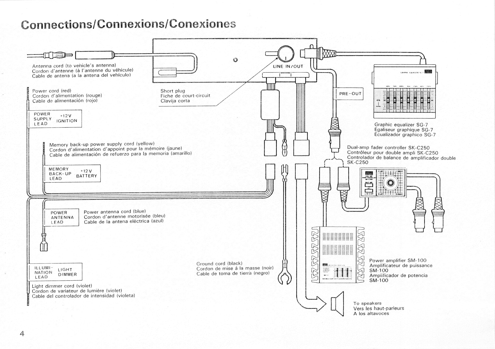
COANE
CEONS
ecea
ec
be
Gace
eneies
Soe
iewaterexeuese
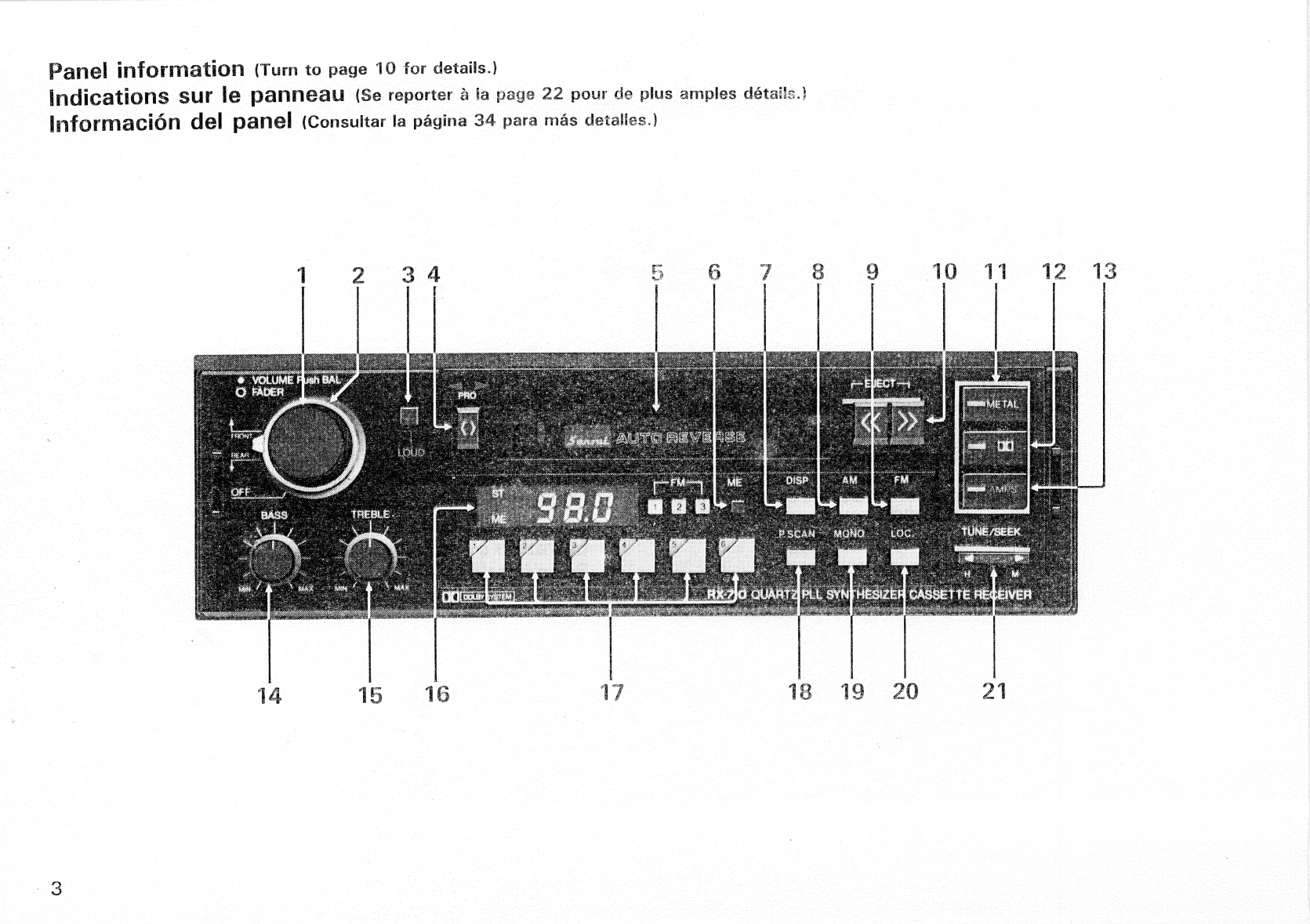
Panel
information............ccccceceecscuceeeecs
Synchronizing
time
Broadcast
reception
Tape
DIAVOdCKy
ssc
Sac
ond
es
se
we
eee
Maintenance
and
Precautions...............
16
SPECITICATIONS
fo
oeiickiscie
esi
eai
via
wc
dives
cece ean’
17
Avant
lUtHISATION..
o.ii
cick
cuca
eee
teee
sai
TS
Procédure
d@
MONtaGe
........cceceeecesereeee
|
CONMROXIONS
cis
g
coo
voces
es
ev
tate
ews
Indications
sur
le
panneau
..............0008:
Synchronisation
de
l’horloge
Réception
de
la
radio
.....
re
eee
ane
Lecture
de
bande..........ccccceeceeeeeneeenenes
Entretien
et
DPECAUTIONS...........cceeeeeeenees
SPECIFICATIONS:
ici
iia
cc
es
eset
esiees
ace
as
oes
Antes
de
ponerlo
en
funcionamiento.....
30
Procedimientos
de
montaje
...............05:
30
CONEXIONGS
6
oiisec
eid
ives
ccivenedevecewedenis
Informacion
del
panel
|
Puestasé6én
AOra
vc
ies
Sea
e
es
RadidrreCe
pion
viii.
eke
ieee
levee
eels
Reproduccion
de
CintaS
............cceeeeee
eee
39
Mantenimiento
y
precauciones.............
40
ESPeCIFICACIONES
..........cccceeeeevececrsetseses
4