if
I
I
CIRCUIT OPERATION DESCRIPTION
1. BASIC OPERATlON OF PULL FREQUENCY SYhfTHESIZER
f-lFZ)2 {
——— ——— .—— ——— ——— ——— ——
7.2MHz Divider Phase detector 11 voltage Control oscillator
oOsc t1Id 1+
fr PD IVco I*fout
Ifr” I
ILow pass filter
Programmable divider L—————.———— —
Prescaler 1I
IP.D. &I
h—— —. ——. -—————. ——— _
m–--– ‘–––––7 “L--- ––(~J~)-– J
I—_——————— ———————— — ;
The illustration above is ablock diagram which is afwrsda-
mental PLL frequency synthesizer.
In order to obtain reference frequeqcy fr, the frequency
of 7.2 MHz generated from acrystal oscillator (OSC) is
passed into adivider circuit of I/d.
This fr is compared with fr’, and runs through phase detec-
tor (PD) “and low pass filter (LpF) to be inverted to direct-
current signal, which is then applied as “varicap voltage of
voltage control oscillator (VCO), thereby control Iing the
oscillation frequency.
This oscillation frequency fout is divided down to l/J$f by
programmable divider (PD), so that one closed loop is fixed
in the relation of
fout =frxN
therefore, the operation of PLL is stabilized
In the case of automatic channel selection, the dividing
ratio Nis altered by the PD by acommand from controller,
and fout is changed accordingly.
Programmable divider
Since the osci Ilation frequency of VCO is very high as
compared with fr, it is divided down to l/N (in the case of
AM) to decrease the difference from fr in this circuit.
Phase detector
This is acircuit to detect the difference in frequency and
phase between reference frequency fr and comparison fre-
quency fr in terms of pulses.
Low passfilter
This circuit is intended to vary and fix the output voltage
in order to deliver avaricap voltage necessary for desired
VCO frequency, on the basis of the output of the phase
detector.
Prascaler
The local oscillation frequency in FM is higher than the
operating speed of the programmable divider of PLL, there-
by opposing to accurate operation. To avoid this, the local
oscillation frequency is preliminarily divided down in this
circuit to aproper frequency permitting reliable operation
of the programmable divider.
Pulse swallow count system is employed. Acouple of pro-
grammable divider (swallow counter and programmable
counter) can be selected.
l-T~~——————
———————
Swallowcounter l/Nl 1
fosc Jcontroller
Ifr’
I1l/N2 Ii
L—-————— ——— —.-2
Programmable divider (N1<N2)
fosc= {(M+l) N1+M (N2--N1)} fr’
=(MN2+N1) fr’
Prescaler IM+ IM
,I
Swallow counter INI
Programmable counter
The prescaler at first starts the frequency division with the
ration M+l. Then swallow counter and programmable
counter start counting simultaneously. When N1inputs are
applied, swallow counter stops counting. Then the frequen-
cy division ratio of the prescaller is switched to M. Program-
mable counter continues to count however and stops when
the input reaches N2. The frequency division ratio of the
prescaller switches back to M+l ard swallow counter and
programmable counter start to count again.
FM reception employs the pulse swallow count system. AM
reception does not employ the pulse swallow count system
but employs the direct frequency division system and so
only programmable counter is operated.
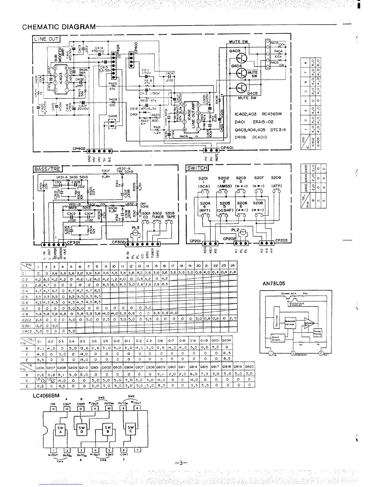
2. GENERAL DESCRIPTION OF LOGIC IC (IC202)
@IC202 LC7218M
This IC includes PLL and controller is aC-MOS LSI for dig-
ital tuning of FM/AM PLL frequency synthesizer system
and controls such functions as FM/AM automatic chan-
nel selection, preset memory and frequency digital
display with Prescaler and liquid crystal digital frequency
display driver. His packed in a24-pin fiat package.
3. AUTO STOP
If count start, when High level signal is applied to SD ter.
minal (Pin No. 15). Then IF freqs.sency became 10.7 MHz
~30k Hz at FM or 450kHz &3kHz at AM. When SD and IF
is agreed radio auto search tuning stops.