manuals.online logo
Brands
  1. Home
  2. •
  3. Brands
  4. •
  5. Sanyo
  6. •
  7. Microwave Oven
  8. •
  9. Sanyo EM-V890 Operating manual

Sanyo EM-V890 Operating manual

Other manuals for EM-V890

1

Other Sanyo Microwave Oven manuals

Sanyo EM-S6786V User manual

Sanyo

Sanyo EM-S6786V User manual

Sanyo EM-5646 User manual

Sanyo

Sanyo EM-5646 User manual

Sanyo EM-U1000W Use and care manual

Sanyo

Sanyo EM-U1000W Use and care manual

Sanyo EM-S2297V User manual

Sanyo

Sanyo EM-S2297V User manual

Sanyo EMS5595S - Microwave 0.9 Cubic Feet Use and care manual

Sanyo

Sanyo EMS5595S - Microwave 0.9 Cubic Feet Use and care manual

Sanyo EM-S1577W User manual

Sanyo

Sanyo EM-S1577W User manual

Sanyo EM-V890 User manual

Sanyo

Sanyo EM-V890 User manual

Sanyo EM-S8597W User manual

Sanyo

Sanyo EM-S8597W User manual

Sanyo EM-D953 User manual

Sanyo

Sanyo EM-D953 User manual

Sanyo EM-X470 User manual

Sanyo

Sanyo EM-X470 User manual

Sanyo EM-Z2100GS - 8 Cubic Foot Microwave Use and care manual

Sanyo

Sanyo EM-Z2100GS - 8 Cubic Foot Microwave Use and care manual

Sanyo EM-G4750EES User manual

Sanyo

Sanyo EM-G4750EES User manual

Sanyo 437 373 72 User manual

Sanyo

Sanyo 437 373 72 User manual

Sanyo EM-SL30NEUK User manual

Sanyo

Sanyo EM-SL30NEUK User manual

Sanyo EM-Z2100GS - 8 Cubic Foot Microwave User manual

Sanyo

Sanyo EM-Z2100GS - 8 Cubic Foot Microwave User manual

Sanyo EM-S7595S User manual

Sanyo

Sanyo EM-S7595S User manual

Sanyo EM-S8597V User manual

Sanyo

Sanyo EM-S8597V User manual

Sanyo EM-SL100NUK User manual

Sanyo

Sanyo EM-SL100NUK User manual

Sanyo EM-S7595S User manual

Sanyo

Sanyo EM-S7595S User manual

Sanyo EMS5595S - Microwave 0.9 Cubic Feet Use and care manual

Sanyo

Sanyo EMS5595S - Microwave 0.9 Cubic Feet Use and care manual

Sanyo EM-X680S User manual

Sanyo

Sanyo EM-X680S User manual

Sanyo EM-C5779V User manual

Sanyo

Sanyo EM-C5779V User manual

Sanyo EM-S3579V User manual

Sanyo

Sanyo EM-S3579V User manual

Sanyo EM-C160US Operating manual

Sanyo

Sanyo EM-C160US Operating manual

Popular Microwave Oven manuals by other brands

Sharp R-390D manual

Sharp

Sharp R-390D manual

PROFILO MD1000 instruction manual

PROFILO

PROFILO MD1000 instruction manual

Candy MIC 201 EX User instructions

Candy

Candy MIC 201 EX User instructions

PITSOS GMW3101B user manual

PITSOS

PITSOS GMW3101B user manual

Sears 5648744780 Use & care manual

Sears

Sears 5648744780 Use & care manual

BOMANN CB 1272 Instruction manual & guarantee

BOMANN

BOMANN CB 1272 Instruction manual & guarantee

Conrad Electronic 2372935 operating instructions

Conrad Electronic

Conrad Electronic 2372935 operating instructions

GE Spacemaker JVM1440BH datasheet

GE

GE Spacemaker JVM1440BH datasheet

DAEWOO ELECTRONICS KOR-6L8K5S83 Operating instructions & cook book

DAEWOO ELECTRONICS

DAEWOO ELECTRONICS KOR-6L8K5S83 Operating instructions & cook book

DAEWOO ELECTRONICS KOR-1N5A9S Operating instructions & cook book

DAEWOO ELECTRONICS

DAEWOO ELECTRONICS KOR-1N5A9S Operating instructions & cook book

Daewoo KQG-6617G Operating instructions & cook book

Daewoo

Daewoo KQG-6617G Operating instructions & cook book

Samsung M1779 Owner's instructions

Samsung

Samsung M1779 Owner's instructions

GE JES1143 Use and care & cooking guide

GE

GE JES1143 Use and care & cooking guide

Miele H6200BM(TB) Operating and installation instructions

Miele

Miele H6200BM(TB) Operating and installation instructions

Jocel JMO011480 instruction manual

Jocel

Jocel JMO011480 instruction manual

Sharp R-752M Operation manual with cookbook

Sharp

Sharp R-752M Operation manual with cookbook

Electrolux EVL8E00X user manual

Electrolux

Electrolux EVL8E00X user manual

STOVES Q900GRF DO User, installation & servicing instructions

STOVES

STOVES Q900GRF DO User, installation & servicing instructions

manuals.online logo
manuals.online logoBrands
  • About & Mission
  • Contact us
  • Privacy Policy
  • Terms and Conditions

Copyright 2025 Manuals.Online. All Rights Reserved.

i
,.
Si@’Mio
I
IFILE NO. I
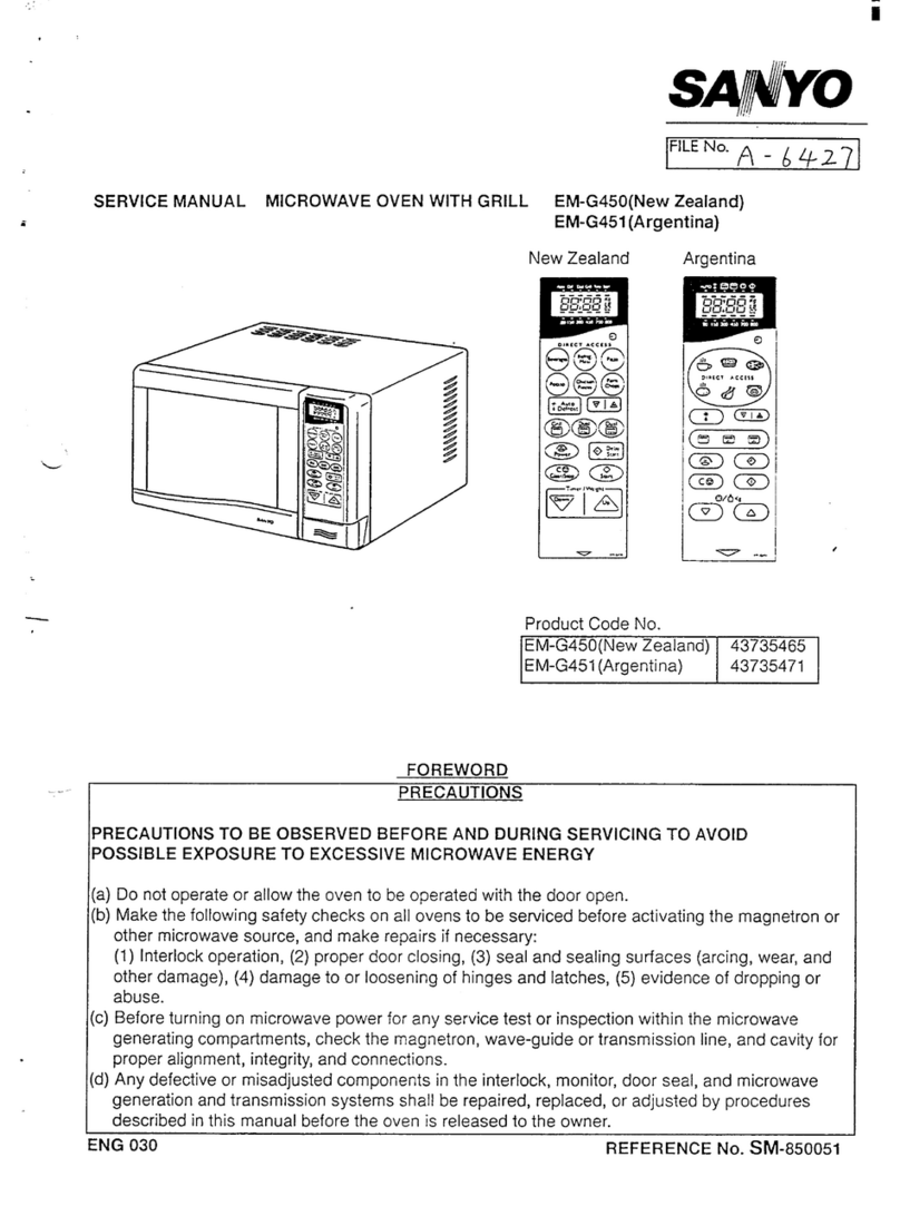
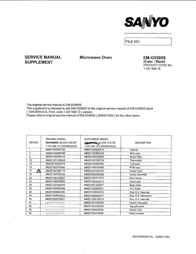
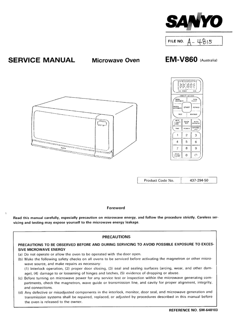
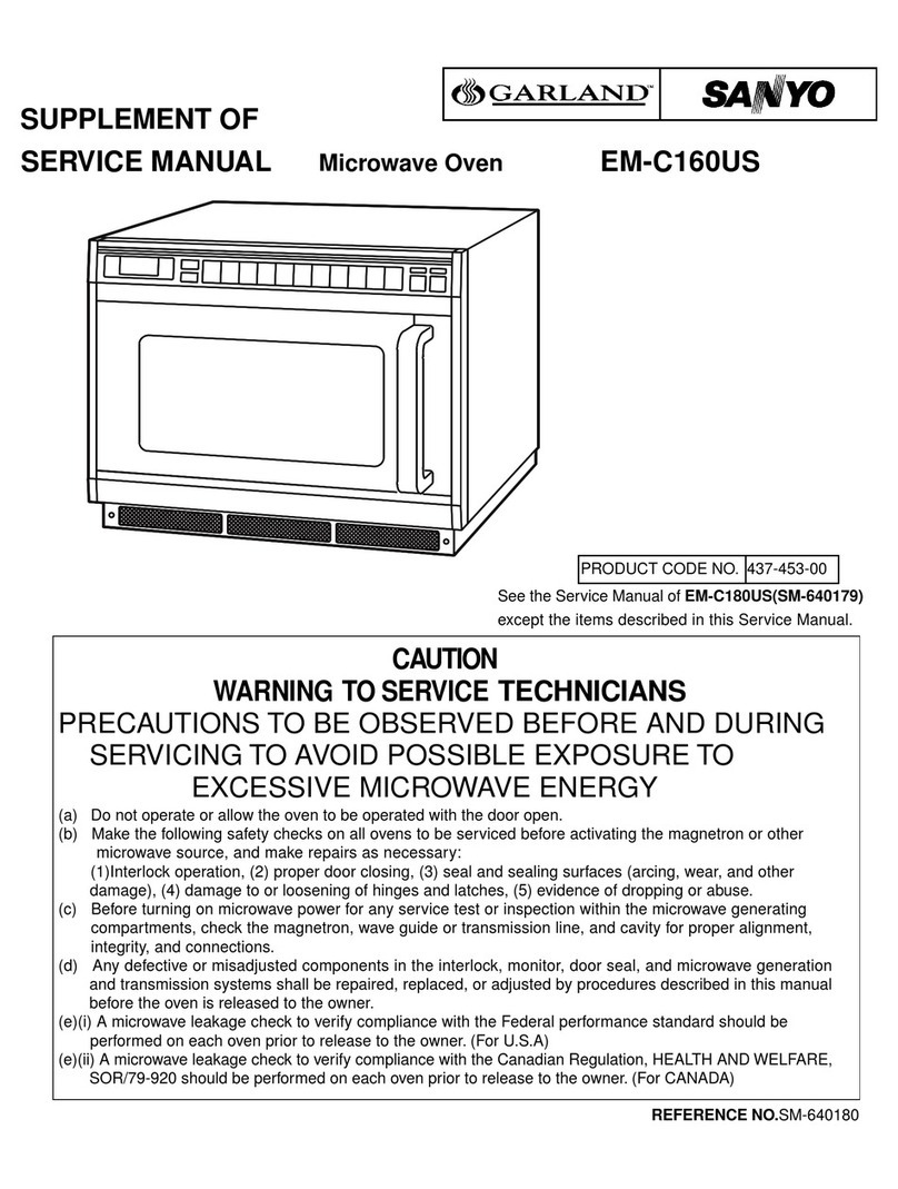
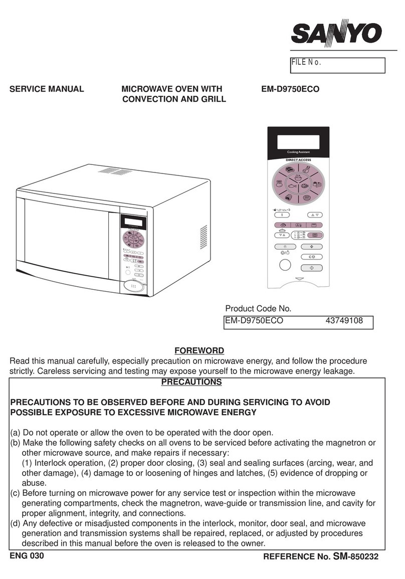
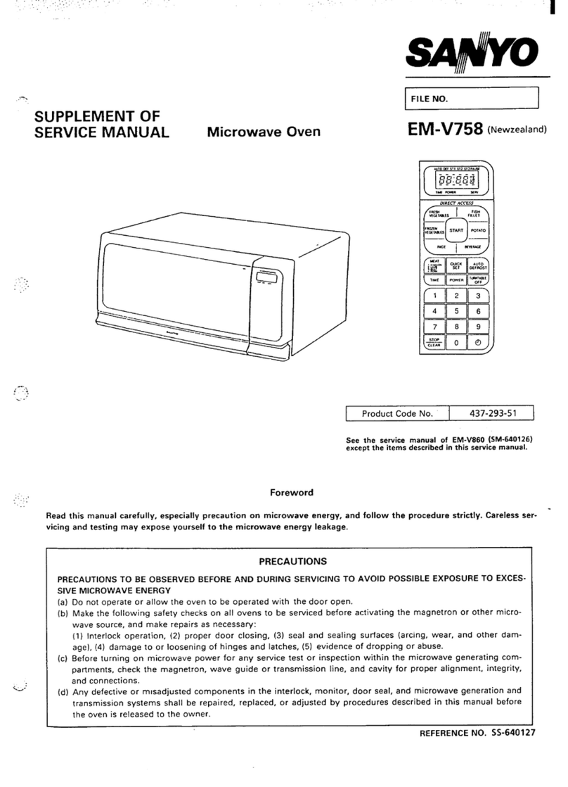
SUPPLEMENT OF
SERVICE MANUAL Microwave Oven EM-V890(NEWZEALAND)
.
—/1
===!9” I
[. .
rProduct Code No. .437-315-01 ]‘
See the service manual of EM-870 ~( WM. “
640208 l-except the items described in this
service manual.
Foreword
Read this manual carefully, especially precaution on microwave energy, and follow the procedure strictly. Careless ser- -
vicing and testing may expose yourself to the microwave energy leakage.
PRECAUTIONS
PRECAUTIONS TO BE OBSERVED BEFORE AND DURING SERVICING TO AVOID POSSIBLE EXPOSURE TO EXCES-
SIVE MICROWAVE ENERGY
(a)
(b)
(c)
(d)
Do not operate or allow the oven to be operated with door open.
Make the following safety checks on all ovens to be serviced before activating the magnetron or other micro-
wave source, and make repairs as necessary:
(1) Interlock operation, (2) proper door closing, (3) seal and sealing surfaces (arcing, wear, and other dam-
age), (4) damage to or loosening of hinges and latches, (5) evidence of dropping or abuse.
Before turning on microwave power for any service test or inspection within the microwave generating com-
partments, check the magnetron, wave guide or transmission line, and cavity for proper alignment, integrity,
and connections.
Any defective or misadjusted components in the interlock, monitor, door seal, and microwave generation and
transmission systems shall be repaired, replaced, or adjusted by procedures described in this manual before
the oven is released to the owner.
REFERENCE NO. SS- 640141
..”
–TABLEOF CONTENTS–
Specifications . . . . . . . . . . . . . . . . . . . . . . . . . . . . 1Test Procedures, ..-,..... . . . . . . . . . . . . . . . 3
Power Output Measurement . . . . . . . . . . . . . . . . . . 1Exploded View and Parts List.... . . . . . . . . . . . 4-8
Circuit Diagram ...........................2 Overall Circuit Diagram . . . . . . . . . . . . . . . . . . . ...9”’
2. pOwER OUTPUT MEASUREMENT
(1) Prepare 1000*5g tap water.
(2) Adjust water temperature to 10”*2”C.
(3) Pour water into acontainer made of borosilicate
glass, 180mm outer diameter cylinder, maximum
3mm thickness.
Note: Use the container kept on the room tempera-
ture.
(4) Place the container in the center of oven cavity.
(5) Set the heating time for 49 seconds and rating full
power and then start oven.
(6) Take the container out immediately when heating
time is up.
(7) Stir water for making even water temperature in the
..
1. SPECIFICATIONS
Rated Power Consumption,, 1,500 W
Microwave Output ................ 1,Ooow
[Adjustable 144W through
1,Ooow)
Frequency .............................. 2,4513 MHz*50MHz
Power Supply ........................ 240 V, 50 HZ
Rated Current ....................... 6.8 .Amp.
Safety Devices ...................... Thermal ProtectoI, Open at
122 ‘C for Cavity
Thermal Protector, Open at
135°C for Manetron
Fuse (Cartridge Type 8A)
Prima~ Interlock Switch
Interlock Monitor and
Door Sensing Switch and Relay 2
Timer ...................................... Electronic Digital, up to
99 min. 99 sec.
Overall Dimensions .............. 550(W) x453(D) x309(H) mm
Oven Cavity Size ................... 377(W) x404(D) x237(D) mm
Turn Table Diameter ............ 360 mm
Effective Capacity of Oven
Cavity ..................................... 31 Jiter
‘Net Weight ............................ Approx. 20 ‘g
,
.
container.
(8) Measure water temperature.
Water temperature rise shall be 8° to 12°C.
–l–
.... .... .“”, . . .. . . .-, . ..
...”
3. CIRCUIT DIAGRAM
240 V50HZ
k-l 4r-$1
i
-.
.,:.
:?:>,
. .
.. ‘. .
:..’.
-.:.’-
FUSE I~-Lil
L
ys!
8A(T) I—=—-J I
@\ ITHERMAL PROTECTOR
I
II
FOR CAVITY OPEN 122i5° C
On 650JIH IBR
[~”~ ;
n
~
i!0.068pF(x~
I
1- T
~2x2200PF(Y1
———— —— BK
CAVITY LAMP
w
wBK
THERMAL PROTECTOR
FOR MAGNETRON OPEN
135t5°c (
w
f
r-
W
_______-
j~~NNECTOR
-J
GEAR MOTOR
f>SK
w
@g;;~gK
SWITCH
f>0
NC* NO
BLOWER MOTOR
CONNECTOR HIGH VOLTAGE TRANSFORMER
r_._— -——— -———. —— 1
J
-——.———
G‘“2
RELAY 2
+-’
‘l@ n’ I
J:’”” II II
%+RELAY311CONNECT: ti______l__D_: ~
i
I
BK\
I
I
I
I
I
/
I
I
I
I
T
15
%
S102
IIP~TRI-TI -
!RELAY1
Is 1II
STEP-DOWN
TRANSFOR~ER 3}
r———-
1* IIDOOR
91
—
r
,SENSING DIODE
IICONTROL ISWITCH
CIRCUIT
III@~ MAGNETRON $&.,u. -
BOARD 10MEG.OHM
f!~i 0.97MFD
-=.-.~_J_J ~2.4KVAC
J
I
I
I
I
I
L––.
WIRING COLOR
‘-- BK :BLACK BR :BROWN
w:WHITE
o:ORANGE BL :BLUE
R:RED
Notes: Thesigrr~ –Theparts marked with~ are supplied high
voltage which isexceeded250V.
The sign @-Thepa~s marked with @have specialchar-
acteristicsimportant for microwave leakage.
When replacingany of these parts use only
manufacturer’sspecified parts.
1- .— -J
————— .—— ——— “J ~
————
BK
Figure 1
-2–
4. TEST PROCEDURES
\
<.
.“.
:. .,
,-
:,.
,,. .
.<
‘,. .
–3–
. .. ,.-. ...’.... . . ... .
.. i
5. EXPLODED VIEW AND PARTS LIST
CAVITY PARTS
..-.
.-. ..
.>--.2
-. .’-
....
21
Key
No. Part No. Description Q’ty
16171246377 Cabinet (Also order Circuit Diaqram 1
-when replacing Cabinet. )
24110825201 Screw, Truss Hd.Tapping, 4x10mm 7
3411 1606007 Screw. Tapping TRS +SRT 4x10mm 3
.4 6171452013 Oven Cavity’** (Not service Part) 1
56171451399 Bottom Plate*** 1
66171445435 Plastic Foot with Canoe Clip 4
7411 0110802 Bolt, Hex. Hd. Machine with Spring 2
Washer &Bolt Washer, 5x14mm,
86171240795 Hinge Lower*** 1
94110892500 Washer, 5mm, U1
10 4110105808 SCR EVR PAN 4x10mm 2
’11 6171305616 Gear Motor M2LJ50ZA12 1
12 6171208481 Insulation Sheet 1
‘Items not illustrated
3
Key
No. Part No. Description Q’ty
13 6170805315 Special Washer 1
14 6171514155 Turn table Shaft 1
15 6171242416 Roller 1
16 6171098372 Rotating Tray 1
17 6171281149 Duct, Humidity Senser 1
18 6171473865 Humidity Sensor 1
19 4110076900 Screw, Pan Hd.,Tapping, 3x6mm,
6171451573 Cavity Cover 2
20 1
21 411 1606106 Screw S- TPG TRS +SRT 4x10mm 1
22 6171184679 Insulation Sheet 1
23 411 1606205 Screw TPG TRS +SRT 4x10mm 1
24 6171241235 Thermostat Cavity 122°C 1
●6171623628 Name Plate 1
●6171623611 Circuit Diagram 1
–4–
-., ....- .. . . . . .. . .
.“
““’”
SWITCHES AND MICROWAVE PARTS
27
(l”
Notes The sign ❑-The pa ❑
rts marked with $are supplied high
voltage which is exceeded 250V.
The sign @-The parrs marked with@ have special char-
acteristics important for microwave leakage.
When replacing any of these parts use onlv
manufacturer’s specified parts,
Key
No. Part No. Description C1’ty
1 411 0825201 Screw, Truss Hd. Tapping, 4x10mm 6
26171385113 Power Supply Cord Complete 1
3 6171569605 High Voltage Transformer, 1
H5T-V860SAP
46171505603 Duct, Msg. Inlet 1
56171385984 Stay, Cavity &Magnetron 1
64110076900 Screw, Pan Hd. Tapping, 3x6mm,
C2-2 2
7~1”~ 124 f259 Thermostat, Magnetron, 135CC 1
84,50023308 Magnetron. 2M247H(8)*** 1
94230227503 Fuse, 250 V8A 1
10 6171414042 Terminal Circuit 8oard Complete 1
11 6171451627 Lead Wire Ass’y with Diode 1
12 617124379? Lead Wire Ass’y (Transformer to 1
Capacitor)
13 6171378870 Capacitor Band 1
14 6171449716 High Voltage Capacitor, l.1mfd.2.1 KV 1
15 6171241082 Space Partition (Blower) 1
16 6171306927 Blower Motor 1
17 4110772109 Screw, Truss Hd. Tapping, 2
4x20mm, Z1-1
Key
No. Part No. Description f.1’ty
18 6170751179 Blower Fan 1
19 411011 5609 Bolt HEX C-SCT 4x20 3
20 6171405330 Duct, Mag, Exhaust 1
21 6171103618 Lamp, 2413v25W 1
22 6171241280 Lamp Socket 1
23 6171241181 Latch Lever*** 1
24 6171524741 Micro Switch, primary, and Door** 2
Sensing V-5930D***
2.5 617004 557s Micro Switch, Interlock Monitor 1
V-5220 DZ***
27 6171241174 Lever Stopper’** 1
29 411 1025808 Screw, E- Tapping TRRS +TW 2
,4x10 mm, Z1
30 411 1606007 Scr~w TPG TRS +SRT 4x10mm 1
31 411 1606106 Scre~ S-TAP TRS +SRT 4x1O mm 2
32 411 0014704 Screw, Pan Hd. Tapping, 4x1O mm, 1
Z1
33 6171325713 Insulation Sheet 1
,-..-
....’
,,.
..
.
.,
–5-
....’”. .. ’.’ .,. . . .
.’ i
DOOR PARTS
8***
/’
45 /7 *** 4*** c
-,
...-
[
Key
No.
1
2
3
4
5
\
\
●** ALL SERVICE (3N MICROWAVE OVENS SHOULD BE PERFORMED BY AtXJALIFIED TECHNICIAN
USING APPROVED TESTING EQUIPMENT. CUSTOMERS SHOULD NOT ATTEMPT TO REPLACE PARTS
IDENTIFIED BY ATRIPLE ASTER ISK(**’)
Pan No. Description —
6171520934 Door Cover**”
6171520941 Door Panel’”
6171385908 Door Main Frame ”’”lAlso order
Door Sheet when replacing Door
Main Frame)
6171520958 Choke Dielectric”*’
6171246483 Door Sheet*”* 1
Q’ty
1
1
1
1
1r
Key
No. Part No.
64110541903
7 6171240955
84110110802
Description
Nut. Hex. Hd. with Washer, 5mm
Hinge, Upper**”
Bolt, Hex. Hd. Machine with Spring
Washer and Bolt Washer, 5x14mm,
~,,..
Spring***
Door Latch***
,10 ***
***
a’ty
2
1
2
1
1
–6-
... . .. .. . .. . .
CONTROL PANEL PARTS
3-6 ***
1***
\
4***
2***
\\
9
\8***
***
5***
7
,~-.
.,
.“..
,-,
:..
,.,
●** ALL SERVICE (3N MICROWAVE OVENS SHOULD BE PERFORMED BY AQUALIFIED TECHNICIAN
USING APPROVED TESTING EQUIPMENT. CUSTOMERS SHOULD NOT ATTEMPT TO REPLACE PARTS
IDENTIFIED BY ATRIPLE ASTER ISK(”*”) ~
Key
No. Part No. Description at y
16171623505 Control Sheet””* (Also order Touch 1
Key Board When replacing Control
sheet)
26171623512 Touch Key Board*’* (Also order 1
Control sheet when replacing Touch
Key Board)
36171514346 Control plate”’” 1
46171521030 Control Frame*** 1
Key
No. Part No. Description Q’ty
6171623567 Operating Instructions 1
6171623642 Carton Box Complete 1
iTy
No.
5
6
7
8
9
—
Part No. IDescription
6171623161 Control Base’”
6171616767 Power &Control Circuit Board
Complete
411 1295805 Screw, Bin Tapping, 3X10mm
6170809559 Spring, Door Release Lever***
6171514339 Door Release Lever”’*
-i
Q’ty
1
1
--l
3
2
1
–7-
CONTROL CIRCXJIT BOARD
(Part No. 617161 6767I) ~‘P-6
.’. -
TP-2 —
.-.,
:.
,...
TP-3 -
o
—TP-7
—TP-4
—TP-1
Ground
‘TP-5
– 8–
“’m
+-
R143
10R
11
6. OVERALL CIRCUIT DIAGRAM ‘61/$1
~80/At
,..
~5G
371
>?0
P45
.-..
.’ . ..
P47 /1:
L
W142
!OK
5102 12
Acz30v-24av/5oHz
1
AL
FUSE =I650 PHx2
THERMAL
0.068 u F PROTECTOR
THERMAL T=200PFx2
PROTECTOR
000R u
*
SENSING 0102
1N4002 -5V
SWITCH 4?orl 4700
i
I29
I
L.—-—. J
OPEN ~
UI04
27,7
R105
??n
11 0103
1SS132
pglu
n
PRIMARY
INTERLOCK
SWITCH
:E:;;:
n
BLOWER
nMOTER
L
RL2 ,< RL2 +r-———-
121
0102
C3330 I
L——__—J
0104
1SS132
RL1 Q106 ,$
330fl OPEN ~
rRlto I
3. 3x
3i,, I
BZl
62KM1 Q109
-15V lK
(~MAGNETRON
d
r,
r(2J @ @ @Slol
10P
o6~POWER BEVEBAGC (@ -G123,,, lx 5
,,,
1 7 OEFROST MEAT FfEtiEAT @~R124 lK 33
2 8 9125, ,, ~K 34
POTATO Hi/LO :::::: 8
3 9 Iflzo,,, lK 35
CASSE80LE START V#aIlbo L@s 9
4STOP o
CLEAR ‘lME -’ FISH R127 lK 36
~
1
—
—
—
.-
.
.
u
Rlll k
lK ,010s
I01 A123Y
I
N
.I0105
.I15 S132 27
._L—-————A —
0! Q113
nI?112
010K 4’TK C102
I%
~F
/50v
011 1
()+0. Iv
013 CI06
--- 11N4002 1M4002
51 0. Olu Zoll
+/Fiov If05. 6ESB3
Zola C13 E
@Dt3ESE2
IRll 47”
Cll z1d.7K z?10V
/1000W :
/25v ;
~
.————-—
~2
Y
1°
I
I
I
I
I
I
JI
>I
~1 I
I
I
I
I
I
I
1
~-5,
II iI Ill
.013
Ill
011 A564A
IzBB27 o-12V 6-5V
0106
1SS132 . .
. . AIOv r
‘1 R13 220n
I,,,, +
I,,, A’15 10K
JR14’
A>20n
~dy Ov f
~..
--- ————-—
J
PT1 P05M-v890 – 9–