Sanyo MCH-900F User manual

Service Manual CD Portable
FM Stereo/AM
Cassette Recorder
Specifications
(CASSETTE SECTION )
Recording system . . . . . AC bias, 4track stereo
Erasing system ....... Magnet erase
Tape speed .......... 4.75 cm /sec.
Fast forward and
rewind time .......... 110 sec. (C-60 tape)
Frequency response . . . 80-12,000 Hz (Normal tape)
(CD SECTION )
Channels ... ........ 2channels
SIN ratio ........... 70dB
Wow &Flutter . . . . . . . . undetectable
Sampling frequency . . . 44.1 kHz
Quantization ......... 16 bits linear /ch
Pick-up light source .Semi-conductor laser
Pick-up wave length .790 nm
Laset output ......... Continuous wave
max. 0.6 mW
Specifications subject to change without notice.
(RADIO SECTION )
Tuning ranges .........
Antennas . . . . . . . . . . . . .
(GENERAL)
Output power . . . . .
Speaker . . . . . . . . . . . . . .
Terminal impedance . .
Power Source .........
Memory back-up (CD) ...
Dimensions ...........
Weight . . . . . . . . . . . . . .
.4
FILE NO.
M~~-900F (AU)
PRODUCT CODE No.
142 963 02
FM:88-108 MHZ
AM :525-1,710 kHz
Built-in ferrite bar and
telescopic rod antennas
4.0 Wx2(DC max.)
12 cm x2, 4ohms
PIEZO X2
PHONES :32 ohms
MIC :200-600 ohms/mV
AC :230-240 V, 50 tiz
DC: 12V
(8 x“D “size batteries)
DC :6V
(4 x“AA HP7/R6° size batteries))
460 (W) x220 (H) x245 (D) Imm
Approx. 4.8 kg without batteries
REFERENCE No. SM580346

CONTENTS —
LASER BEAM SAFETY PRECAUTIONS . . . . . . . . 1
OPERATING THE RESET SWITCH . . . . . . . . . . . 1
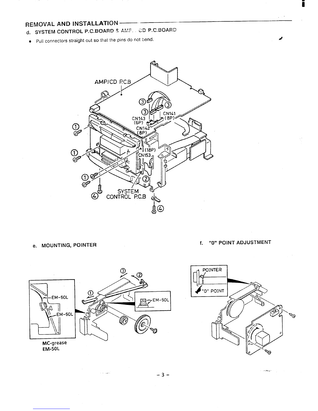
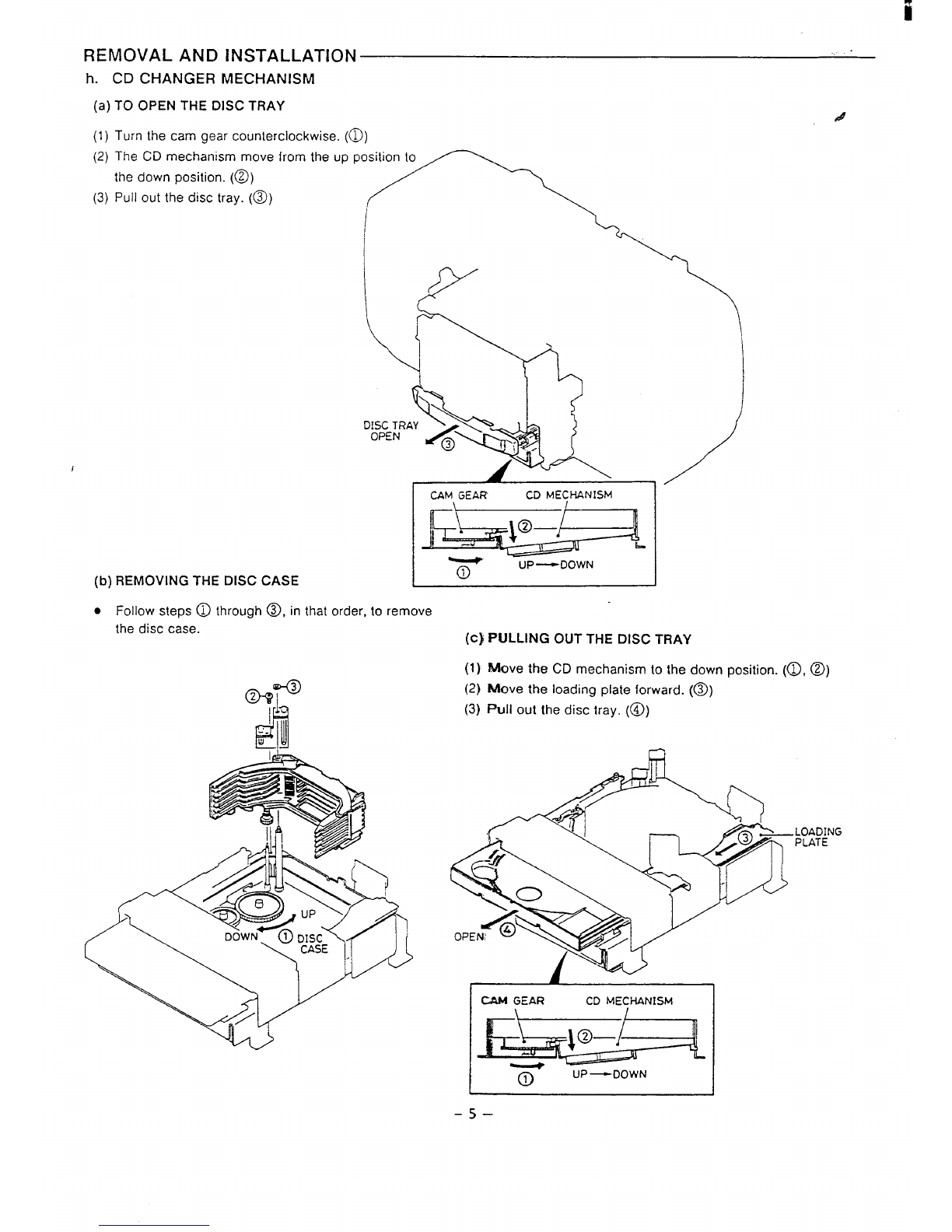
REMOVAL AND INSTALLATION ............. 2
TUNER ADJUSTMENTS ..................-6
TAPE DECK ADJUSTMENTS ...............7
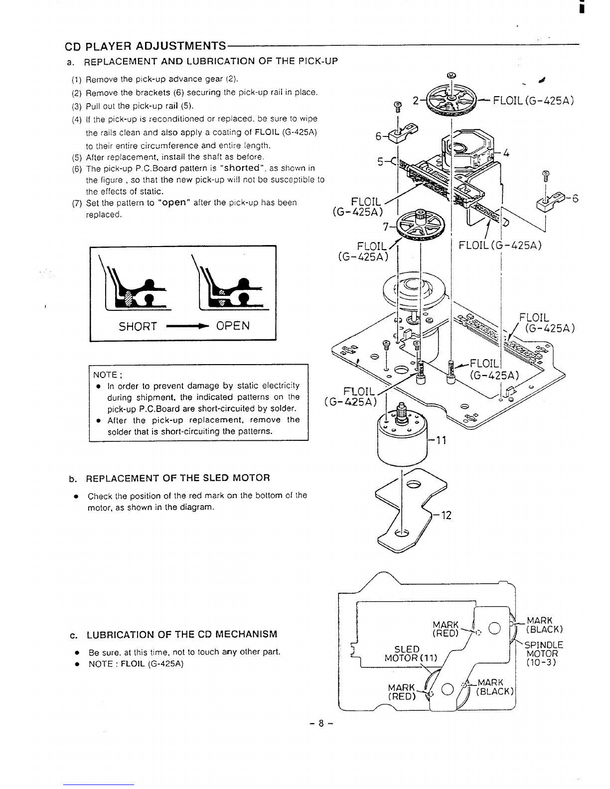
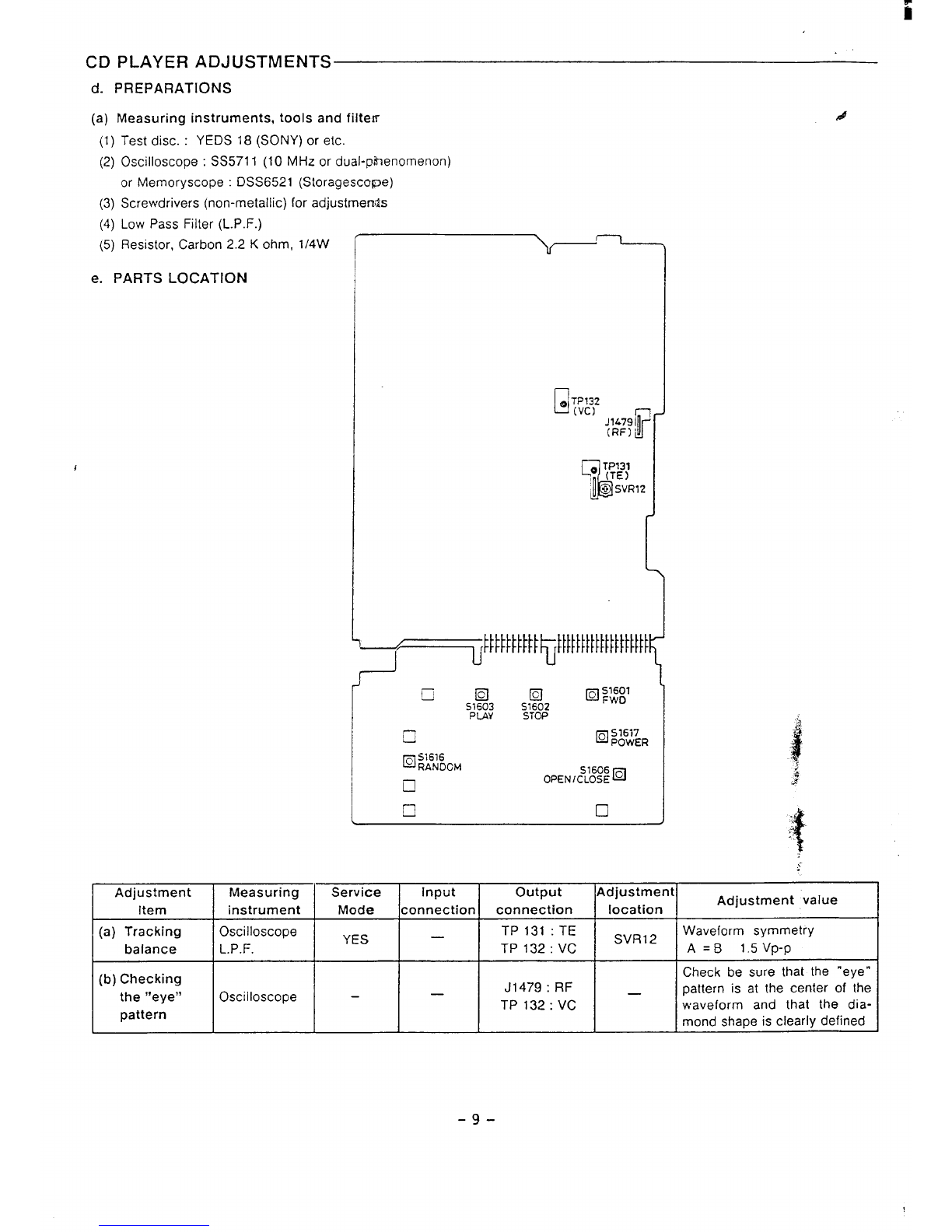
CD PLAYER ADJUSTMENTS ...............8
SERVICE MODE .........................11
CD CHANGER MECHANISM OPERATION
DESCRIPTION .........................-14
LASER BEAM SAFETY PRECAUTIONS—
.Pick-up that emits alaser beam is used in this CD player.
CAUTION :
USE OF CONTROLS OR ADJUSTMENTS
OR PERFORMANCE OF PROCEDURES
OTHER THAN THOSE SPECIFIED
HEREIN MAY RESULT IN HAZARDOUS
RADIATION EXPOSURE
LASER OUTPUT ........0.6mW Max. (CW)
WAVELENGTH ........... KIO nm
REPLACING THE PRINCIPAL PARTS &
OF THE CD CHANGER MECHANISM .........17
EXPLODED VIEW ........................25
PARTS LIST ...........................27
IC BLOCK DIAGRAM &DESCRIPTION ........38
SCHEMATIC DIAGRAM ....................40
WIRING DIAGRAM . . . . . . . . . . . . . . . . . . . . ...41
CD CHANGER BLOCK
SYSTEM CONTROL TERMINAL LEVELS .......63
CD CHANGER BLOCK FLOWCHART .........65
CLASS 1LASER PROOU
LUOKAN 1LASERLAIT
KLASS 1LASERAPPAR
CAUTION–INVISIBLE LASER RAOIATION
WHEN OPEN AND INTERLOCKS OEFEATEO.
AvOIOEXPOSURE TO BEAM.
,AOVARSEL-USYNLIG LAiEtiTRALING VEO A8NING.
NAR SIKKERHEOSAF8RYDERE ER UOE AF FUNKTION,
UNOGk UDS /ZTTELSE FOR STR~LING.
VARNING–0SYNLN3 LASER STR~LNIN.G NAR
OENNA DEL AR OPPNAO OCH SPARR AR URKOPPLAO.
STRALEN AR FARLIG.
VORSICHT-UNSICHTBARE LASERSTRAHLUNG TRITT AUS.
‘WENN OECKEL GEOFFNET UNO WENN SICHERHEITSVERRIEGELUNG
uBERBRUCKT [ST. NICHT, OEM STRAHL AUSSET2EN. A
VARO! .Avawssa fa suoialuk!lus. ohilellaes~a Olel allliina
nakyma!lomalle Iasemileilylle. Ali kalso saleeseen. II
OPERATING THE RESET SWITCH
WHAT TO DO IF ...
If the operation of the unit or display is n
normal, disconnect the power cord from the P
outlet and remove the batteries (if applicabl[
then press the RESET bulton (back of the un
for at least 20 seconds.
-1-

I
ii
REMOVAL AND INSTALLATION *,.
●
●
●
●
●
●
a.
This CD-radio-cassette player employs achanger mechanism as its CD block.
Care should be exercised when removing and reinstalling it.
All wiring should be returned to the original position after work is complete= 4
First have ready many the new FIXERS (614246 5271) for replacement. %
Arrange the lead wires so that they are not near the heat sink. .
Remove any discs that are loaded in the CD changer. ...
Before disassembling the unit, set the POWER switch to the “OFF” positio~”
and wait 10 seconds while the CD changer mechanism enters standby stat&..
Then unplug the unit and begin the disassembly procedure. -2
CABINET
(1) Remove the battery lid.
(2) Remove the 8rear cabinet mounting screws.
4. --
c. CD CHANGER MECHANISM
BLOCK &P. C. BOARDS
—/’-’--k
.
b. TAPE MECHANISM
s---
.,
.\. y
IJ
–2-

REMOVAL AND INSTALLATION
(j. SYSTEM CONTROL P. C. BOARD SAMF. CD P. C. BOARD
●Pull connectors straight out so that the pins do not bend. J
AMPICD
$0
4
e. MOUNTING, POINTER f. “0” POINT ADJUSTMENT
1
II
MC-grease
EM-50L
... -3- -*..,

... ,.
REMOVAL AND INSTALLATION
g. WIRING LAYOUT
‘a)ANTENNk (b) TAPE MECHANISM #
(c) SPEAKER
I
(’/
— 5-5 TuRN
(d) CD CHANGER MECHANISM
7“7
‘“p’~””’p+g-m
~+ PRINT SIDE
●The CD changer mechanism and CD mechanism move
forward and back, and to the left and right.
Arranq& the lead wires as shown in the diagram.
VIEW -A
FIXER
~
IMOTOR
1f?C.B
FIXER
/
lr-r--=-
.Positiom the flexible P.C. board connected to the CEI
changer connector P.C. board so that it is not loose.
-4-

REMOVAL AND INSTALLATION
h. CD CHANGER MECHANISM
(a) TO OPEN THE DISC TRAY d
(1) Turn the cam gear counterclockwise. (~)
(2) The CD mechanism move
the down position. (~)
(3) Pull out the disc tray. (@))
1
(b) REMOVING THE DISC CASE
‘romtheuppo;n
CAM GEAR CD MECHANISM
1+ \,&
.pk
--, .,.,
—
T‘p‘UUWN
.Follow steps @through ~, in that order, to remove
the disc case. (c} PULLING OUT THE DfSC TRAY
(1) Move the CD mechanism to the down position. (~,@)
(2) Rllove the loading plate forward. (~)
(3) Pull out the disc tray. (@)
Q
IMGEAR CD MECHANISM
TUP—DOWN
-5–

TUNER ADJUSTMENTS
.Use aplastic screw driver for adjustments.
●Adjust the intermediate frequency of AM and FM to the frequency of ceramic filter.
Supply voltage
Phones impedance :
Standard output
Function switch
PARTS LOCATION
a. AM ADJUST
Adjusting
Step Circuit
1IIF
i
2Tuning
3coverage
i-
4Tracking
5
DC 12.0 V
32 oh!m
&5 mW (126 mV)
RADIO f
IENT BAND SELECT SWITCH :
Connections
Input output
Closed the output Connect sweep
terminal by sweep generator to
generator, it place C2106 (H) &
to L2103. TP202 (G)
Connect AM SG Connect VTVM to
to Test Loop speaker terminals
Connect AM SG Connect VTVM to
to Test Loop speaker terminals
6lRepeat adjustments
455 kHz ILow IXF213
517k Hz Low end L2104
1750 kHz High end VCT -4
600 kHz 600 kHz L2103
1400 kHz 1400 kHz VCT -3
VTVM
Oscilloscope
-4-
Max.
Max.
I
b. FM ADJUSTMENT BAND SELECT SWITCH :FM FM Dummy antenna :75 ohm unbalance
r
Adjusting Connections
Step Circuit SG Frequency Position of tuning dial Adjustment
Input output
Connect sweep Connect sweep
1IF generator to generator to
IC201 @(H) C2106 (H) 10.7 MHz Low ..-
&TP202 (G) &TP202 (G)
2Connect FM SG
Tuning Connect VTVM to 87.0 ~~Z Low end L2102
to TP201 (H) &
3coverage TP202 (G) speaker terminals 109.0 MHz High end VCT-2
Connect FM SG Connect VTVM to
4Tracking to TP201 (H) &speaker terminals 98.0 MHz 98.0 MHz VCT- 1
TP202 (G)
5lReDeat adjustments
VTVM
Oscilloscope
A
Max
Max.
I
-6–

iii
. .
TAPE DECK ADJUSTMENTS
a.
(a)
●
●
●
(b)
(1)
(2)
(3)
(4)
(5)
b.
(a)
I
(b)
HEAD REPLACEMENT AND HEAD AZIMUTH ADJUSTMENT
HEAD REPLACEMENT 4
After replacement, demagnetize the heads by using adegausser.
Be sure to clean the heads before attempting to make any adjustments. 21P HEAD
Ml wiring should be returned to the original position after work is completed. LOW
HEAD AZIMUTH ADJUSTMENT
Load the test tape (VIT-703, etc., 10 kHz )for azimuth
adjustment.
Press the PLAY button.
Use across-tip screwdriver to turn the screw for azimuth
adjustment so that the left and right output are maximized.
Press the the STOP button.
After completion of the adjustment, use thread lock (TB-1401 B)
to secure the azimuth-adjustment screw.
MOTOR REPLACEMENT AND SPEED ADJUSTMENT
MOTOR REPLACEMENT
MOTOR SPEED ADJUSTMENT
(1) Insert the test tape (MTT-lllN, etc., 3000 Hz).
(2) Press the PLAY button.
(3) Use aflat-tip screwdriver to turn the SVR (located inside the rear
of the motor) to adjust SVR so that the frequency counter
becomes 3,000 Hz.
c. CHECKING THE MECHANISM TORQUES AND TENSION
WHiTE
HEAD AZIMUTH ADJ.
MOTOR SPEED
.Clean the head, capstan and pinch roller before making any measurement.
Measurement Take-up torque Back tension Tape tension
Cassette for PLAY:TW-211 1A Orive-power cassette
PLAY: TW-21 11A
measurement F.FWD/REW:TW-2231 TW-2412
PLAY 30-60 gr.cm 2.0- 4.5 gr.cm 60 gr or more
F.FWD 55-120 gr.cm
REW 55-120 gr.cm —
-7–

CD PLAYER ADJUSTMENTS
a. REPLACEMENT AND LUBRICATION OF THE PICK-UP
(1)
(2)
(3)
(4)
(5)
(6)
(7)
Remove the pick-up advance gear (2).
Remove the brackets (6) securing [he pick-up rail in place.
Pull out the pick-up rail (5).
If the pick-up is reconditioned or repiaced, be sure to wipe
the rails clean and also apply acoating of FLOIL (G-425A)
to their entire circumference and entire length.
After replacement. install the shaft as before.
The pick-up P. C. Board pattern is “shorted”, as shown in
the figure ,so that the new pick-up will not be susceptible to
the effects of static.
Set the pattern to “’Open” after the pick-up has been
replaced.
SHORT ~OPEN
NOTE ;
●In order to prevent damage by static electricity
during shipment. the indicated patterns on the
pick-up P.C.Board are short-circuited by solder.
●After the pick-up replacement, remove the
solder that is short-circuiting the patterns.
b.
●
REPLACEMENT OF THE SLED MOTOR
Check the position of the red mark on the bottom of the
motor, as shown in the diagram.
c. LUBRICATION OF THE CD MECHANISM
●Be sure, at this time, not to touch MY other part.
●NOTE :FLOIL (G-425A)
(
fa d
.4f$iij)
%’2:“-
‘FLOIL(G-425A)
-6
(G-:>
F
(G-425A) I I I
[f I
-8-

iii
CD PLAYER ADJUSTMENTS
d. PREPARATIONS
(a) Measuring instruments, tools and fiiterr
(1)
(2)
(3)
(4)
(5)
Test disc. :YEDS 18 (SONY) or etc.
Oscilloscope :SS5711 (10 MHz or dual-phenomenon)
or Memory scope :DSS6521 (Storagescope)
Screwdrivers (non-metallic) for adjustments
Low Pass Filter (L.P.F.)
Resistor, Carbon 2.2 Kohm, l/4W
e. PARTS LOCATION
1
S1606g
OPEN ICLOSE
In ❑I
.#f
:
Adjustment Measuring Service Input output Adjustment
Item instrument Mode connection connection location Adjustment value
(a) Tracking Oscilloscope YES TP 131 :TE
—SVR12 Waveform symmetry
balance L.P.F. TP132:VC A=B 1.5 Vp-p
(b) Checking Check be sure that the “eye”
J1479 :RF _
the “eye” Oscilloscope –—pattern is at the center of the
TP 132:VC
pattern waveform and that the dia-
mond shape is clearly defined
-9-

i
CD PLAYER ADJUSTMENTS
f. ADJUSTMENTS
(a) Tracking balance adjustment 4
I
(1)
(2)
(3)
(4)
(5) symmetrical, as shown in the illustration.
(6) Switch OFF the POWER.
Within one second after pressing the! OPENICLOSE and
RANDOM switches at the same time. press the FWD TP 131 +
switch. (Service mode: TRACKING BALANCE) (TE) -
Connect an oscilloscopetoTP131 (T=) and TP132 (VC). IN
Set the test disc. TP132&
PLAY switch push ON. (Vc) -
Adjust SVR12 so that the oscilloscope’s waveform is
(b) Checking the “eye” pattern
(1) Switch “ON” the POWER.
(2) Connect an oscilloscope to J1 479 (RF] and TPI 32 (VC).
(3) Load the test disc.
(4) PLAY switch push ON.
(5) Check to be sure that the “eye “pattern is at the center of
waveform and that the diamond shape is clearly defined.
(6) Press the STOP button.
(7) Switch “OFF” the POWER.
L.P. F.
10K
‘7
~ ~ o~c,LLoscop=
T
1*5V
Ov P-P
lV)DIV A=B
2.2K ohm +
Jlf179
(RF) oV&
IOSCILLOSCOPE I
TP132
Wc) 1
NING EXPANOED
-1o-

SERVICE MODE
The unit has four service modes.
e
●
a.
(1)
(2)
After pressing the OPEhl/CLOSE and RANDOM buttons at the same time, press one of the following .~
buttons within one second to enter the corresponding service mode.
IBIJ?TON ISERVICE MODE I
PLAY /PAUSE [KEY WIRING CHECK
PLAY /PAUSE ILED AND LCD WIRING CHECK
FWD CD BLOCK ADJUSTMENT MODE
OPEN ICLOSE CD BLOCK OPERATION DISP~Y
MODE
To cancel the
KEY WIRING
After pressing
service mode, press the POWER button to switch “OFF” the power supply.
CHECK
the OPENfCLOSE and RANDOM buttons at the same time,
press the PLAYIPAUSE button within one second.
The LEDs light and the LCD segments are displayed.
~..–. .—. .—..—..—..—..—..—..—..—..—..—..—..—.. —..—..._ ..—..—.._.. _..
IDISC TRACK
l—
I// /:/ ml
‘HI1-1- 1
III 1I_ :1 ‘/ :/ /:!
:- ALL ~
1RANDOM INTRO REPEAT :
L... ... ... ... ... ... ... ... ... ... ... ... ... ... ... ... ... ... ... ... ... ..J
REW PLAJ ;AUSE ST#P FJD
m
—;---
INTRO
RANDOM —OPEN/CLOSE
-11–

SERVICE MODE
(3) Pressing akey toggles the corresponding LED or LCD display indication on and off.
Pressing the key when the indication is off turns it on, and pressing the key when the indication is on turns it off. #
KEY INPUT DISPLAY
REPEAT IREPEAT
MEMORY PROG.
PLAY /PAUSE lb
POWER IOFF
I
KEY INPUT DISPLAY
LCD LED
FWD DISC
BACK ITRACK
Ill 2—
—1
I_ 2
3❑1
—1 3
141 II
—. I41
(4) Press the POWER button to switch “OFF” the power supply and cancel the service mode.
b. LED AND LCD WIRING CHECK
(1)
J
(2)
(3)
After pressing the OPEN/CLOSE and RANDOM buttons at the same time,
press the PLAYIPAUSE button within one second.
Press the STOP button.
All the LEDs light and all the LCD segments are displayed.
[.—..–.-. --–.-–..–..–..--------- -–-.–..–..–..–..–.. –..–
t ! ➤11 PAUSE RANDOM INTRO CONTINUE REPEAT i
\L... .. . ... ... ... . .. ... .. . ... ... .. . ... . .. .. . .. . ... ... ... ... ... ... ..J
l—l
(n-lr-m
SE@!EM.
51,
3“’co
(4) Press the POWER button to switch “OFF” the power supply and cancel the service mode.
-12–

i
SERVICE MODE
c.
●
d.
(1)
(2)
(3)
(4)
I
CD BLOCK ADJUSTMENT MODE
~efer to the section on CD block adjustments (pages 9 and 10).
CD BLOCK OPERATION DISPLAY MODE
After pressing the OPEN/CLOSE and RANDOM buttons at the same time, press the OPEN/CLOSE
within one second.
When the unit is in this service mode and the CD function is selected,
the LCD numeric display indicates the current CD operation.
If aCD error occurs, anumber is displayed in the seconds indication area.
In addition, the CD operation indication is frozen from that point forward.
Press the STOP button when the unit is in the stop mode {o unfreeze the indication.
button
NUMBER
“SECOND”
.- .---------------------------------1----------
(DISC
i-
1//
I//
:-
1
TRACK
/ :/
1I_
{
‘// I1-/-
:1 ‘1 ‘/n
--
I
I
I
I
L......... ...... ...... ..................... ...... ... ..............J
CD ERROR CONDITION INDICATIONS
1I
NUMBER CD ERROR CONDITION
oNo error.
1Focus failure during focus search.
2No subcode received at disc startup.
3Can’t read TOC.
4Focus lost during servo-on (during play, etc.).
5No subcode received during servo-on
(durinq plav, etc.).
6Tray-open not complete.
7Tray-close not complete.
18 ICD error I
9CD error (chucking failure).
AUnload error (unioad failure).
-13-

CD CHANGER MECHANISM OPERATION DESCRIPTION
●
●
●
a.
●
(1
The unit is capable of loading up to six 12 cm CDs at once and playing them in sequence.
Immediately before power is turned on (off status), it is in the home position. .4
Disc case :Disc 1(top level)
Turntable :Chucking
Loading plate: Holding disc
When the unit is powered on with the CD function selected, chucking takes place on the CD that was programmed when
the unit was last operated and the unit enters the standby mode.
UP/DOWN OPERATION OF THE CD MECHANISM AND DISC CASE
Normally, the UP/DOWN MOTOR (41 4) of the disc case and CD mechanism turns the up/down cam gear (391) of the
CD mechanism in aclockwise direction, causing the up/down switch (393) to move to the “up on” position.
This puts the turntable into chucking status.
When the OPEN/CLOSE button is pressed, the cam gear (391) turns counterclockwise, putting the turntable into the
down position. (CD mechanism: down.)
(2) When the plunger (395) operates, it turns the worm gear (3661. using the gear (408) as ajunction.
This causes the disc case to move up or down.
r(3) The rear of the disc case is equipped with slits (the protrusions to the right of 363) and switches, which cause adisc
case stop signal to be generated.
UPI
CD MECHANISM UP/ DOWN OPERATION
GEAR(408 )
%
CD MECHANISfVl
UPIDOWN CAM GEAR (391)
E& ~,,’ ;(?W
GEAR (-408)
r?
BOSS
+
CONTROL LEVER (407)
:D MECHANISM I
WN M0T0R(414) PLuNGER (395)
,.n’,-n” er. n
DISC CASE &I
D:\
Mu I
(385)
ANISM
GEAR
(408)
DISC CASE UP/ DOWN OPERATION
wy3M&R DISC CASE ELEVATOR
DISC CASE(363) SENSOR P.C.B(315)
I~-
SENSOR
/--
C-’
(k)
‘\, RESET SWITCH
o)
.,, ,1,!,,,, ,,,
Iii
k
w,’ II
‘L
(F=:’ ~
~ “< MOTOR GEAR
(0)
DISC CASE &CD MECHANISM
@J )UP/ DOWN MOTOR(414)
UPI DOWN
SWITCH(393)
-141 –

CD CHANGER MECHANISM OPERATION DESCRIPTION
b.
●
(1)
(2)
(3)
LOADING PLATE MOTION +“’OPENr’
The loading motor (377) runs, and the loading plate (434) starts movtig toward the “OPEN” position, d
..
performing the following operations.
Using hooks a and b on the loading plate (434), the CD is extractecf and moved from the disc case (363).
When it is over the turntable, hooks aand b separate from the CD and retract into the loading plate.
The CD is now “FREE” on top of the loading table.
Next, the loading plate moves further and, by pressing on the Ioadimg table (431), moves the loading table lock
lever (430) .
This causes it to link with the loading table and advance toward the “OPEN” position.
DISC
LOADING
(434) PLATE
I
CMsc I
*
“LOADING PLATE (434)
n
.......................................................................
~Refer to the EXPLODED VIEW on pages 34 and ~
~35 for the numbers of parts not indicated here. :
.......................................................................:
CLOSED
LOADING TABL~ AS5’Y LOADING PLATE J%S’V
(431) -(434) “
-15-

i
I
CD CHANGER MECHAN
DURING PLAY
SM OPERATION DESCRIPTION
Gear for initial opening operation and disc case storage d
Locks and movement starts I@’x2--1
OPEN
1
\
Gear for opening operation
.At initial docking, the plate gear moves the tray, then movement is
continued by the opening gear.
c. LOADING TABLE MOVEMENT +“OPEN”
.As it moves, the loading table performs the following operations.
(1) [t removes the binder from the centering hold lever (322).
(2) It moves the cover plates (425, 427) so that the disc stopper (424) rises up and stabilizes the disc setting.
(3) It sets the OPEN/CLOSE switch (399) to the “OPEN ON” position.
d. LOADING TABLE MOVEMENT -+ “CLOSE”
.After putting the disc in place and pushing the loading table (431} with your hand, the OPEN/CLOSE switch
moves to the “OFF” position, the loading motor reverses, and the loading table begins to move, performing the
following operations.
(1) It lowers the disc stopper (424).
(2) When the disc sensors (345, 450) are triggered, the turntable starts up after operation (3), and the TOC is read.
(3) The loading table guide (355) disengages the loading table lock lever (430).
This undoes the link between the loading table and loading plate.
e. LOADING PLATE MOVEMENT +“CLOSE”
●The loading motor moves the “FREE’” loading plate toward the “CLOSE” position,
causing it to perform the following operations.
(1) [t inserts aCD into the disc case and moves the loading completed switch (314) to the “OFF” position.
(2) Hooks aand b on the loading plate clamp the CD.
(3) Press the POWER button to switch off the power supply and cancel the service mode.
-16-

i
I
REPLACING THE PRINCIPAL PARTS OF THE CD CHANGER MECHANISM
a. SENSOR P.C. BOARD LAYOUT DIAGRAM AND ITS APPLICATION
.The CD changer mechanism employs four sensor P.C. boards. d
.Observe the following precautions to prevent sensor malfunctions.
(1) Mount light-emitting and light-receiving elements on the P.C. boards in their correct positions.
Make sure such parts are not tilted or loose.
ru1
DISC CASE ELEVATOR
SENSOR ,PC.B (315)
I
“sC;Y;:; PI+ :%:. 1J
wPHOTO SENSOR
0.2mm or”more 7VT
i-l-
Detects whether disc is I*DISC CASE
present or absent (363).
Detects chucking errors
La@as!
Should be parallel to P.C. board
....................... .......................
—
M~The height of the P.c. board !
r-+, ;must be adiusted.
mTiF
>E% -+wi%’:.’i’%’?’ Should not be loose
%L-.._xxYA\\ /1’ v v LCD CHANGER CONNECTOR
\. ‘-/ .. -
_‘L ........-#
/-” (434) PHOTO SENSOR
DISC SENSOR P.C.B LOADING PLATE
“LOWER” (345) /~LOADING PLATE
SENSOR P.C.B(304)
h
\+
o,2mm or more~~ ~+ LOADING PLATE
II SENSOR I?C.B (304)
,. -.. .
“’ “+~ O.lmm or more
u
F-
—
No.
304
345
450
315
P.C.BOARD NAME IDESCRIPTION
LOADING PIATE SENSOR P.C.B
DISC SENSOR P.C.B“LOWER”
DISC SENSOR P.C.B“UPPER”
DISC CASE ELEVATOR
SENSOR P.C.B
.Detects the loading status by monitoring the
movement of the loading plate (434).
Tks.e sensors detect the following conditions on
SENSOR P.C. boards 345 and 450.
.Disc present or absent (PCO02/PCO03)
●Chucking error (S005)
.Detects whether DISC CASE is in UP or DOWN
position (PCOO1 ).
.Detects when DISC CASE is in RESET position
(s001).
●Detects when loading plate (434) is in RESET
position (S002).
-17–

ii
REPLACING THE PRINCIPAL PARTS OF THE CD CHANGEF? MECHANISM
b.
●
●
REPLACING THE PLUNGER
Turn the plunger “ON” and “OFF”, and confirm that the position of the controf fever (407) and gear (408) change. .4
To prevent improper movement Of the tip of the control lever (407), confirm that it has no grease on it.
PLUNGER “OFF” PLUNGER “ON”
CD MECHANISM
UPIDOWN CAM GEAR(391)
c.
●
>GEAR (408)
DOWN \GEAR (408)
UP
CQNTnOL
1
LEVER (407)
R
=~~~than0.2mm
~%j ‘~ti-pLuNGER(’”)
~zAR f63 ---)
(408) “* MOTOR GEAR
DISC CASE &CD MECHANISM
o
uP/DOWN MOTOR (414)
o
MOUNTING THE STOPPER AND ARRANGING THE LEAD WIRES
Confirm that the hook on the stopper (353) is not bent.
I
DISC SENSOR f?CB
“LOWER’” (345) OPEN /CLOSE
SWITCH (339)
Arrange the fead wires so that they do not stick out
from the chassis.
This will prevent [hem from getting caught when the
disc tray opens and closes.
-18-

i
REPLACING THE PRINCIPAL PARTS OF THE CD CliAN(3ER MECHANISM
d.
●
●
(a)
●
●
(b)
(1)
(2)
(3)
(4)
(5)
(6)
(7)
(8)
(9)
REPLACING THE DISC CASE ELEVATOR SENSOR P. C. BOARD (315)
This P.C. board performs avery important function. as it must monitor the up, down, and Ioadinq status of the disd-cas%.
When replacinq the P.C. board, be verv careful so as not to adversely affect any of the other parts.
REPLACING THE P.C. BOARD (315)
Follow steps @and @below, in that order, to install the
spring coil (314).
Make sure not to install the spring coil backwards.
P. C. BOARD HEIGHT ADJUSTMENT
Set the POWER switch to the “ON” position and the
FUNCTION switch to the “CD” position.
Press the DISC 1button.
The disc case lowers into position for the first disc.
Adjust the P.C.board height adjustment screw so that
the distance between the disc case and the chassis is
46.0 t0,3 mm.
Next, press the DISC 6button.
Once again, press the DISC 1button.
Set the POWER switch to the “OFF” position and wait
about 15 seconds.
Set the POWER switch to the “ON” position.
Confirm that the distance between [he disc case and
the chassis is 46.0 f0.3 mm.
If the distance is not 46.0 t0.3 mm, repeat steps (2)
through (8).
(1O)After adjustments are complele, apply thread lock
(TB-1401 B) to the screw (31 1).
SPRING
(314)
P
1DISC CASE ELEVATOR
SENSOR PC.B (315)
f[~
–1: ‘Q b
/?+ ~“c ~
=
~
u
L1.“~o [&Q,
000
$
g
BRACKET (313) w?
●After adjusting the height, apply
screw lock to the screw (311).
THREAD LOCK
TB-1401B
T
SCREW
DISC CAS: (363) (311)
-19-
Other manuals for MCH-900F
1
This manual suits for next models
1
Table of contents
Other Sanyo Portable Stereo System manuals