FILE NO
Model NO. C20VTI I-M@
Videocassette Recorder (New Zealand /Oceania)
Service Ref. No. C20VT11 -M@-00
w
t,
;
Contents
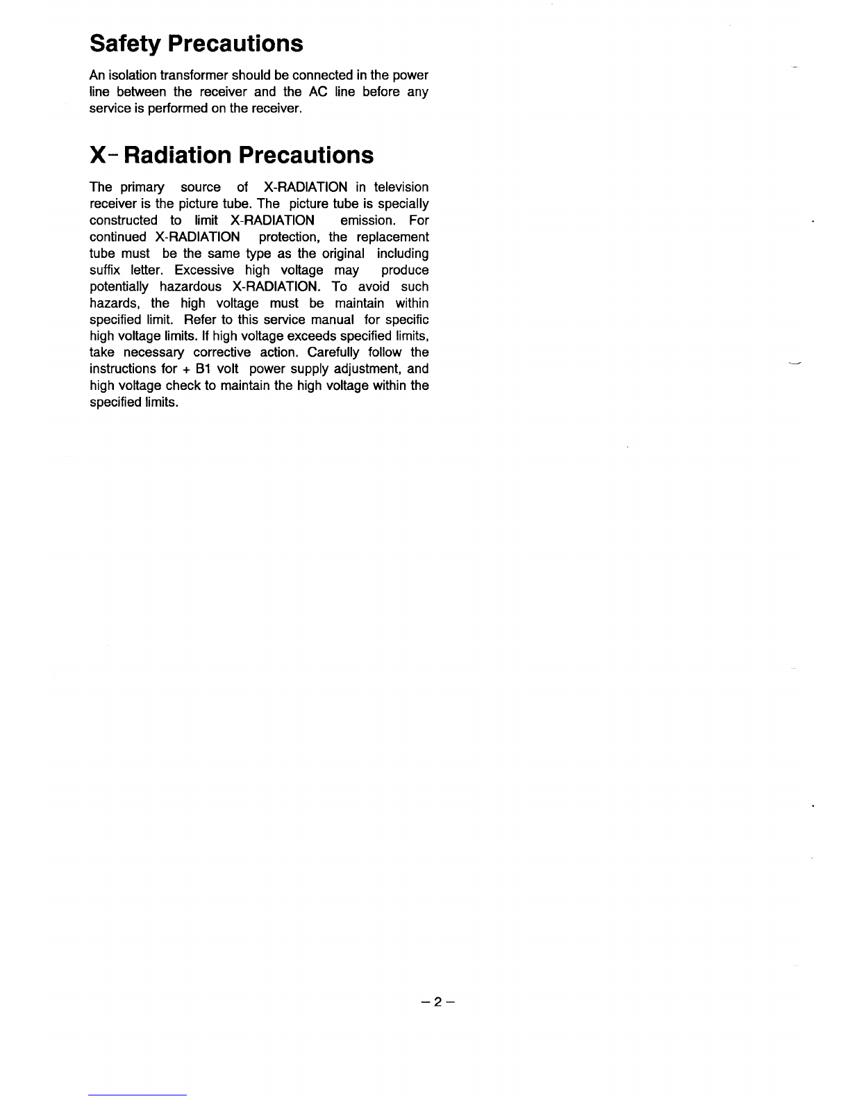
Safety Precautions, X-Radiation Precautions ................. ~
Specifications .....................................................................
1. Mechanical Disassembles
1-1. Cabinet back removal ............................................ 4
1-2. Chassis removal .................................................... 4
1-3. Video mechanism removal .................................... 5
1-4. Service procedure ................................................. 7
1-5. Replacement of the reel drive belt ........................ 8
1-6. Video mechanism disassemblies .......................... 8
1-7. Cassette mechanism assembly .............................11
2, Service Mode ................................................................l2
3. Power Circuit Protection and
Self Diagnosis Display
3-1. Power circuit protection ........................................ 13
3-2. Power circuit problem self diagnosis .................... 13
3-3. VCR self diagnosis ................................................l4
4. ICS Pin Description
4-1. IC800 (CPU) pin description .................................15
4-2. IC1930 (DAC) pin description., .............................l5
5. Service Adjustments (TV Section)
+15V/+1 15V, Vertical size/center, Focus adjustment..l 6
Grey scale, AGC, Horizontal center adjustment .........l7
Horizontal width adjustment, High voltage check ........18
Clock frequency confirmation .......................................l8
6. WF Adjustment ............................................................. 19
7. A7TAdjustment ............................................................2O
8. Purity and Convergence Adjustment ...........................21
Product Code: 111321218
Original Version
Chassis Series: TC2-A
WE
9. VCR Main Mechanism Parts Location
9-1. Mechanism ass’y (Top view) .................................... 22
9-2. Mechanism ass’y (Bottom view) ............................... 23
9-3. Front loading mechanism .......................................... 23
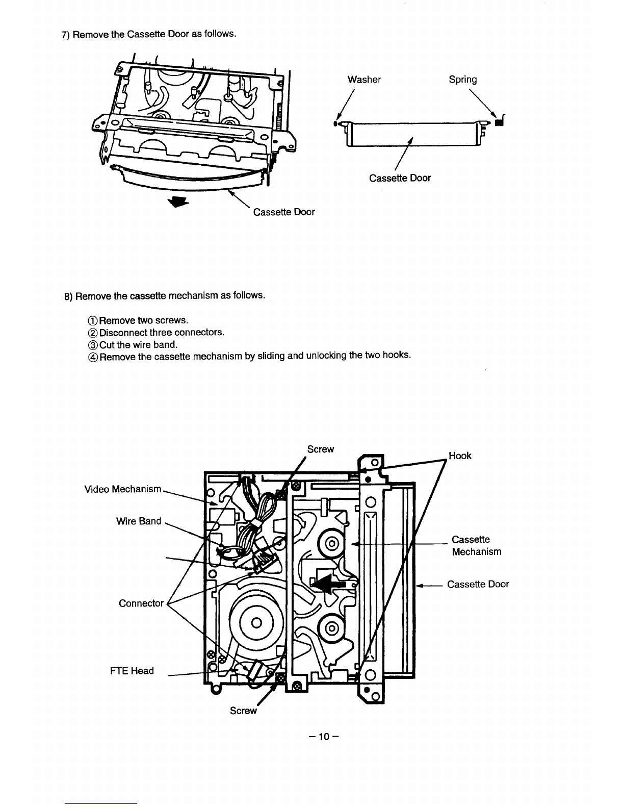
10. Mechanism Dismantling and Reassembling
10-1. Cassette drive gear (Right) ................................... 24
10-2. Cassette drive gear (Left) ..................................... 25
10-3. COMPL motor bracket (Loading motor block) ..... 26
10-4. Tape loading mechanism ...................................... 29
10-5. Capstan motor ....................................................... 32
11. VCR Service Adjustments
11-1. Test points for tape path adjustment .................... 33
11-2. Location of adjustment point ................................. 33
11-3. Sewicejigs ............................................................ 34
11-4. Mode selector (VHJ-0050) handling instruction ... 35
11-5. Tape path adjustment ........................................... 37
11-6. Servo circuit adjustment ...................................... 39
11-7. Audio circuit adjustment ...................................... 39
11-8. Video still V-lock adjustment ................................ 40
12. Mechanism Maintenance and Checking
12-1. Periodic checking and maintenance items .......... 41
12-2. l_#mwo~e~roceedwhen the cassette cannot be
................................................................ 42
13. Cabinet Parts tist ........................................................... 43
14. Video Section Parts List ................................................ 44
15. TV Section Chassis Electrical Parts List ........................ 49
REFERENCE NO. SM 520130
(E7WY)


 User manual")