Sanyo CE32FWN6F-C User manual

Part No. SKSM0810 C7ZES JULY 2005
Colour Television
Service Manual
Model CE32FWN6F-C
Service Ref. No. CE32FWN6F-C-00
PRODUCT CODE: 111375104
ORIGINAL VERSION: Chassis No.EB8-A
Give complete "SERVICE REF. NO." for parts
order or servicing, it is shown on the rating sheet
on the cabinet back of the TV set.
Note
This TV receiver will not work properly in foreign
countries where the television transmission
system and power source differ from the design
specifications. Refer to the specifications for the
design specifications
CE32FWN6F-C
Contents
Safety precautions/Specifications ..................................................................................................................2
Block diagrams ..............................................................................................................................................3
Cabinet Disassembly......................................................................................................................................4
Adjustment and Repair Procedures............................................................................................................5~9
CPU Functions ..............................................................................................................................................................................10~11
Component Locations ..................................................................................................................................12
IC Block Diagrams..................................................................................................................................13~15
Pin description of semiconductors................................................................................................................16
Part Description and reading of schematic diagram ....................................................................................17
Cabinet Parts List/TV Stand parts list ..........................................................................................................18
Electric Parts List....................................................................................................................................19~25
-+
Please use Schematic Diagram SKP20542
with this Service Manual.

-2-
C7ZES
SAFETY PRECAUTION
X-RADIATION PRECAUTION
The primary source of X-RADIATION in the television receiver is the picture tube. The picture tube is specially
constructed to limit X-RADIATION emissions. For continued X-RADIATION protection, the replacement tube
must be the same type as the original including suffix letter. Excessive high voltage may produce potentially
hazardous X-RADIATION. To avoid such hazards, the high voltage must be maintained within specified limit.
Refer to this service manual, high voltage adjustment for specific high voltage limit. If high voltage exceeds
specified limits, take necessary corrective action. Carefully follow the instructions for +B1 volt power supply
adjustment, and high voltage adjustment to maintain the high voltage within the specified limits.
PRODUCT SAFETY NOTICE
SPECIFICATIONS
Product safety should be considered when a component replacement is made in any area of a receiver.
Components indicated by mark in the parts list and the schematic diagram designate components in which
safety can be of special significance. It is particularly recommended that only parts designated on the parts list in
this manual be used for component replacement designated by mark . No deviations from resistance wattage
or voltage ratings may be made for replacement items designated by mark .
!
!
!
1: An isolation transformer should be connected in the
power line between the receiver and the AC line
when a service is performed on the primary of the
converter transformer of the set.
2: Comply with all caution and safety-related notes
provided on the cabinet back, inside the cabinet, on
the chassis or the picture tube.
3: When replacing a chassis in the cabinet, always be
certain that all the protective devices are installed
properly, such as, control knobs, adjustment covers
or shields, barriers, isolation resistor-capacitor networks
etc. Before returning any television to the customer,
the service technician must be sure that it is completely
safe to operate without danger of electrical shock.
Power source AC 220~240V, 50Hz
Television system System I
Colour system PAL/NTSC4.43 (PAL/NTSC4.43/NTSC3.58 IN AV MODE)
Receiving channel UHF: #21~69
Aerial input impedance 75ohm
Rear AV terminal
AV1: CENELEC standard
INPUT: Composite video, RGB and Audio L/R
OUTPUT: TV-output with composite video and audio L/R
AV2: CENELEC standard
INPUT: Composite video, RGB, S-VHS and Audio L/R
OUTPUT: Monitor output with composite video and Audio L/R
Front AV terminal
AV3: RCA jacks
INPUT: Composite video and Audio L/R
Sound output(Music) 12 x 2
Dimensions (WxHxD) 880 x 575 x 549mm
Weight 49.5 Kg
Important recycling information.
Your SANYO product is designed and manufactured with high quality
materials and components which can be recycled and reused.
This symbol means that electrical and electronic equipment, at their
end-of-life, should be disposed of separately from your household
waste.
Please dispose of this equipment at your local community waste collec-
tion / recycling centre.
In the European Union there are separate collection systems for used electrical and electronic
products.
Please help us to conserve the environment we live in!
Note: This symbol mark and recycle system are applied only to EU countries and are not applied
to other countries of the world.

-3- C7ZES
BLOCK DIAGRAM
This is a diagram for all models and therefore differs slightly from the actual block diagram.
IC601
TN6Q04
C609
D610
14v IC645
5v
P.F
2
4
1
25v
D671
7v
3v3
ON/OFF
UOC PIN 107
Q651
Q642
+14v
-14v
Q625
Q682
145v
Q641
Q675 St-BY UOC
PIN 106
AC
A101
TUNER
X122
X121
5v30v
5
A1901
RC RECEIVER
PF
Q866
IC001
AUDIO AMPLIFIER
SPEAKER
SP901
SP902
KEY SW
IC801
MEMORY
1V8_1 Q202 Q201
1V8_2 Q203
Q204
TO UOC PINS
93 & 96
TO UOC PINS
3,100,117,118,124
UOC
Q1001
Q1002
SC_1 B-IN
SC_1 G-IN
SC_1 R-IN
SC1 FB IN
K1001
SCART 1
SC_1 VIDEO OUT
SCART 1 AUDIO L/R IN
SCART 1 AUDIO L/R OUT
SC_1 VIDEO IN
Q1003
Q1004
SCART 2 AUDIO L/R IN
SCART 2 AUDIO L/R OUT
K1101
AV3 AUDIO L/R & VIDEO IN
145V
Q439
Q431 Q432
L461
L462
Q462
Q461
HORIZONTAL
SCAN COIL
D441
Q402
Q403
ON/OFF CONTROL
CPU PIN 106
200v
To CRT
Q401
T451 FLYBACK
CRT
Heater
IC7 01
SCREEN & FOCUS
H.V
R OUT
GOUT
BOUT
IK
PICTURE TUBE
VERTICAL
SCAN COIL
V-OUTPUT
LA78045
IC501
X201
I2C BUS CONTROL
14
10
9
106
107
11
9
22 23 2
128
48
75
72
71
70
51
53
54
84 85 86
6
58
62
63
SC_2 FB -IN
SC_2 G -IN
SC_2 B- IN
SC_2 R-IN
K1002
SCART 2
SC_2 VIDEO OUT
SC_2 VIDEO IN
49
50
43
55
34
35
36
37
108 109
120
31
127 60 61 97
29
30
80
79
78
77
24
25 IF IN
SIF IN
SW601
T611
CONVERTER
IC666
3v3 St-By
Outline

-4-
C7ZES
(A) (A)
CABINET DISASSEMBLY
CABINET BACK DISASSEMBLY
1. Remove 11 screws(A) for 32”
2. Pull out the cabinet back.
(A)
(A)
(A)
(A)
(A)
(A)
(A)
(A)
(A)
ANT.75Ω
FRONT
/DAVANTI
L/S
R/D
INT EXT/EST
REAR
/POSTERIORE

-5- C7ZES
OPTION SETTING
[After replacing the Memory IC (IC801)]
The memory IC, IC801, stores the option data of TV set and service adjustments data for each circuit, therefore,
when the memory IC is replaced, it should be programmed to the following settings and “SERVICE ADJUSTMENT”
on pages 6 to 9.
To enter to the Option Mode
+ Press and hold the F/OK button on the remote control and P▼button on the front panel of the TV. The option
window will appear on the screen.
To set the Option Mode
+ Highlight the desired option item by using the P▲or P▼ button .
+ To switch the option mode, use the Volume - (LEFT) or Volume + (RIGHT) button.
+ The data which is set in the option mode is stored into the memory IC automatically.
The following table shows the available option items and default setting mode.
Exit from the Service Mode
+ Press the MENU button.
Option Mode Mode Description & Note
SORT MODE SORTING or Tuning mode, default “SORTING”
TUNING
P & P ON or OFF Plug & Play mode, default “ON”
WEL. TEXT ON or OFF Display message when first set up, default “ON”
AUTO VOLUME ON or OFF Auto volume default “OFF”
SURROUND ON or OFF Surround sound default “ON”
VIRT SUB WOOFER ON or OFF Virtual Sub Woofer default “ON”
COUNTRY UK or IRE or TV system, default “BG/DK/I/LL’”
BG/DK / I / LL’
WIDE ON or OFF Wide mode, default ON
AV3 ON or OFF Front AV disable, default “ON”
TEXT NO SIGNAL ON or OFF Disables Text when no signal, default “ON”
AFC ON or OFF Auto Frequency Control default “OFF”
SORT MODE SORTING
P&P ON
WEL.TEXT ON
AUTOVOLUME OFF
SURROUND ON
VIRT SUBWOOFER ON
COUNTRY B/G, D/K, I, L/L'
WIDE ON
AV3 ON
TEXT NO SIGNAL ON
AFC OFF
OPTION
ADJUST : EXIT : RECALL
OPTION MODE FOR CE32FWN6-F-C-00
i
/

-6-
C7ZES
SERVICE ADJUSTMENTS
After replacing the Memory IC (IC801)]
The memory IC, IC801, stores the service adjustments data for each circuit, therefore, when the memory IC is
replaced, it should be programmed by using “OPTION SETTING” on previous page and the following adjustments.
ADJUSTABLE SERVICE ADJUSTMENT
Service Item Number. Symbol 1 Symbol 2 Frequency Wide Mode
13 A01 Track. mode 50Hz Full Track. Mode(HCO)
14 A02 Vert. Zoom 50Hz Full Vertical zoom
15 A03 Vert. Slope 50Hz Full Vertical slope
16 A04 Vert. Shift 50Hz Full Vertical shift
17 A05 Vert. Ampl. 50Hz Full Vertical amplitude
18 A06 S-Corr. 50Hz Full S-correction
19 A07 V.Lin.Ctrl. 50Hz Full V.Lin.Ctrl.
20 A08 V.Linearity 50Hz Full V.Linearity
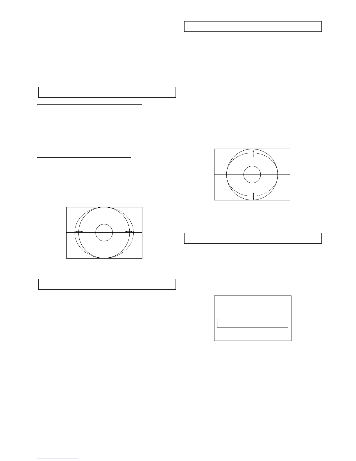
21 A09 EW Width 50Hz Full EW width
22 A10 Hor. Shift 50Hz Full Horizontal shift
23 A11 EW Parabola 50Hz Full EW parabola/width
24 A12 Trapezium 50Hz Full EW trapezium
25 A13 UC Parabola 50Hz Full EW upper corner parabola
26 A14 LC Parabola 50Hz Full EW lower corner parabola
27 A15 Hor. Bow 50Hz Full Horizontal bow
28 A16 Parallel 50Hz Full Horizontal parallelogram
29 A17 Vert. Scroll 50Hz Full Vertical Scroll
30 A18 H BLK SW 50Hz Full RGB blanking mode
31 A19 H BLK L 50Hz Full Timing of wide blanking front(WBF)
32 A20 H BLK R 50Hz Full Timing of wide blanking rear(WBR)
33 A21 OSVE 50Hz Full Black current measuring lines in overscan
34 A22 EVB 50Hz Full Extended vertical blanking
35 B02 Vert. Zoom 50Hz Natural / or 4:3 squeeze mode Vertical zoom
36 B09 EW Width 50Hz Natural / or 4:3 squeeze mode EW width
37 B10 Hor.Shift 50Hz Natural / or 4:3 squeeze mode Horizontal shift
38 B11 EW Parabola 50Hz Natural / or 4:3 squeeze mode EW parabola/width
39 B12 Trapezium 50Hz Natural / or 4:3 squeeze mode EW trapezium
40 B13 UC Parabola 50Hz Natural / or 4:3 squeeze mode EW upper corner parabola
41 B14 LC Parabola 50Hz Natural / or 4:3 squeeze mode EW lower corner parabola
42 B15 Hor.Bow 50Hz Natural / or 4:3 squeeze mode Horizontal bow
43 B16 Parallel 50Hz Natural / or 4:3 squeeze mode Horizontal parallelogram
44 B17 Vert. Scroll 50Hz Natural / or 4:3 squeeze mode Vertical Scroll
45 C02 Vert. Zoom 50Hz Zoom14:9 Vertical zoom
46 C11 EW Parabola 50Hz Zoom14:9 EW parabola/width
47 C13 UC Parabola 50Hz Zoom14:9 EW upper corner parabola
48 C14 LC Parabola 50Hz Zoom14:9 EW lower corner parabola
49 C17 Vert. Scroll 50Hz Zoom14:9 Vertical Scroll
50 D02 Vert. Zoom 50Hz Title14:9 Vertical zoom
51 D03 Vert. Slope 50Hz Title14:9 Vertical slope
52 D11 EW Parabola 50Hz Title14:9 EW parabola/width
53 D13 UC Parabola 50Hz Title14:9 EW upper corner parabola
54 D14 LC Parabola 50Hz Title14:9 EW lower corner parabola
55 D17 Vert. Scroll 50Hz Title14:9 Vertical Scroll
56 E02 Vert. Zoom 50Hz Zoom16:9 Vertical zoom
57 E11 EW Parabola 50Hz Zoom16:9 EW parabola/width
58 E13 UC Parabola 50Hz Zoom16:9 EW upper corner parabola
59 E14 LC Parabola 50Hz Zoom16:9 EW lower corner parabola
60 E17 Vert. Scroll 50Hz Zoom16:9 Vertical Scroll
61 F02 Vert. Zoom 50Hz Title16:9 Vertical zoom
62 F03 Vert. Slope 50Hz Title16:9 Vertical slope
63 F11 EW Parabola 50Hz Title16:9 EW parabola/width
64 F13 UC Parabola 50Hz Title16:9 EW upper corner parabola
65 F14 LC Parabola 50Hz Title16:9 EW lower corner parabola
66 F17 Vert. Scroll 50Hz Title16:9 Vertical Scroll
67 G02 Vert. Zoom 50Hz Normal Vertical zoom
68 G09 EW Width 50Hz Normal EW width
69 G10 Hor. Shift 50Hz Normal Horizontal shift
70 G11 EW Parabola 50Hz Normal EW parabola/width
71 G13 UC Parabola 50Hz Normal EW upper corner parabola
72 G14 LC Parabola 50Hz Normal EW lower corner parabola
73 G17 Vert. Scroll 50Hz Normal Vertical Scroll
74 G18 H BLK SW 50Hz Normal RGB blanking mode
75 G19 H BLK L 50Hz Normal Timing of wide blanking front(WBF)
76 G20 H BLK R 50Hz Normal Timing of wide blanking rear(WBR)
77 H21 OSVE 50Hz Squeeze Black current measuring lines in overscan
78 H22 EVB 50Hz Squeeze Extended vertical blanking
Explanation
Item No. OSD Description
7 Screen adjustment
151 WPR - N R - Drive adjustment
152 WPG - N G - Drive adjustment
304 AGC Take Over AGC adjustment
314 TXT - H - POS OSD Positioning adustment
IMPORTANT NOTICE
Do not attempt to adjust service adjustments not listed above otherwise it may cause loss of performance and product safety.
GEOMETRY SERVICE DATA

-7- C7ZES
To enter to the Service Mode
+ Press and hold the GREEN button on the remote control and then press the P▼button on the cabinet.
To select the service item and change data value
+ To select the adjustment item, use the P▲or P▼button.
+ To change the service data, use the Volume -(LEFT) or Volume + (RIGHT) button.
+ The data which is set in the service mode is stored into the memory IC automatically.
SERVICE MODE
SERVICE SERVICE SOFTWARE
ITEM ITEM VERSION
NUMBER DESCRIPTION
Exit from the Service Mode
+ Press the MENU button or turn off the TV set by using the Mains switch.
INITIALISATION OF MEMORY IC
To initialise the memory IC (IC801), press and hold the NORMAL button on the remote control, then press
the P▼button on the front panel of the TV set. The tv set will switch into standby mode. Turn the Mains switch Off
and On, then switch on from standby. The initialisation is now completed.
When initialised the memory IC and all of the setting data (option data and service adjustment data) stored in the IC
are reset to the default value. It is necessary to set the option settings and readjust the service adjustments listed in
this manual and to re-tune all the channels.
SERVICE
000 EB8A 3_52

-8-
C7ZES
ADJUSTMENTS
IMPORTANT NOTICE
Do not attempt to adjust the following service adjustments except when adjustments are required in servicing
otherwise it may cause loss of performance and product safety.
1. Receive white raster pattern.
2. Set controls to normal.
3. Connect digital voltmetre to test point TP-B and GND.
4. Adjust voltage to 145 ±0.5V by using VR641.
1. Input and tune an RF signal which is VHF to the clear-
est station.
2. Connect digital voltmetre to test point TP-A and GND.
4. Enter the service mode and select item no. 304. AGC
TAKE OVER
5. Press the LEVEL+ or LEVEL - button to adjust volt-
age to be 3.2Vdc.
By using FOCUS VR, adjust focus control for well
defined scanning lines.
SCREEN ADJUSTMENT
1. Enter the service mode and select item no. 6.
COLLAPSED LINE
2. Turn screen VR until collapsed line is just visible and
then stop turning. Press menu key on remote control
to exit the service mode.
DRIVE ADJUSTMENT
3. Select item no.151. WPR - N (R-Drive) or 152. WPG -
N (G-Drive) and adjust both initially to 20.
4. Change data value of each item by using LEVEL + or
LEVEL - button to obtain the proper white balance.
PCC ADJUSTMENT
1. Receive cross hatch pattern and set screen mode to
“FULL”.
2. Enter the service mode and select item no. 23. EW
PARABOLA
3. Press the LEVEL+ or LEVEL - button to adjust the
vertical line to be straight.
TRAPEZOID ADJUSTMENT
1. Receive cross hatch pattern and set screen mode to
“FULL”.
2. Enter the service mode and select item no. 24.
TRAPEZIUM
3. Press the LEVEL+ or LEVEL - button to correct the
trapezum distortion of the vertical line.
PCC ADJUSTMENT
GREY SCALE ADJUSTMENT
FOCUS ADJUSTMENT
AGC ADJUSTMENT
+ B VOLTAGE ADJUSTMENT

-9- C7ZES
CORNER ADJUSTMENT
1. Receive cross hatch pattern and set screen mode to
“FULL”.
2. Enter the service mode and select item no. 25. UC
PARABOLA for top corner adjustment OR item no.
26. LC PARABOLA for bottom corner adjustment.
3. Press the LEVEL+ or LEVEL - button to correct the
distortion of the vertical line around the corners.
HORIZONTAL CENTRING ADJUSTMENT
1. Receive circular pattern and set screen mode to
“FULL”.
2. Enter the service mode and select item no. 22. HOR.
SHIFT.
3. Press the LEVEL+ or LEVEL - button to adjust the
horizontal centre.
HORIZONTAL WIDTH ADJUSTMENT
1. Receive circular pattern and set screen mode to
“FULL”.
2. Enter to the service mode and select item 21. EW
WIDTH.
3. Press the LEVEL+ or LEVEL - button to adjust the
horizontal width.
1. Receive circular pattern and set screen mode to
“FULL”.
2. Set controls for brightness and contrast to maximum.
3. Connect high-voltage meter to the anode of CRT and
GND.
4. Confirm that voltage is 30.5 kV ±1.0kV at maximum
beam current 1.45mA ± 0.05
VERTICAL CENTRING ADJUSTMENT
1. Receive circular pattern and set screen mode to
“FULL”.
2. Enter the service mode and select item no.16.VERT
SHIFT.
.3 Press the LEVEL+ or LEVEL - button to adjust the
vertical centre.
VERTICAL HEIGHT ADJUSTMENT
1. Receive circular pattern and set screen mode to
“FULL”.
2. Enter the service mode and select item no. 17. VERT
AMPL.
3. Press the LEVEL+ or LEVEL - button to adjust the
vertical height.
1. Receive circular pattern and set screen mode to
“FULL”.
2. Enter the service mode and select item no. 314. TXT -
H - POS.
3. Press the LEVEL+ or LEVEL - button to adjust
proper OSD positioning.
OSD POSITIONING ADJUSTMENT
VERTICAL ADJUSTMENT
HIGH-VOLTAGE CONFIRMATION
HORIZONTAL ADJUSTMENT
314 TXT - H - POS 7

-10-
C7ZES
CPU PORT FUNCTIONS
Pin No Function Name Function In/Out
1 VSS Gnd --
2 VSS Gnd
3 1v8_1 1.8v Supply --
4 3v3 3.3v Supply --
5 Vref 3.3v Reference --
6 Vref V Ref Gnd --
7 Vref 3.3v Reference --
8 Vref V Ref Gnd --
9 Vref 3.3v Reference --
10 XTAL IN Clock Oscillator In
11 XTAL OUT Clock Oscillator Out
12 Vss Gnd --
13 Vguard sw --
14 Dec Dig 1.8v source supply Out
15 5v 5v Supply --
16 Phi 2 Phi 2 --
17 Phi 1 Phi 1 --
18 Gnd Gnd --
19 Sec pii --
20 Dec BG --
21 EW Drive parabola out Out
22 VdrB Vertical drive B Out
23 VdrA Vertical drive A Out
24 Vif 1 Vision IF 1 In
25 Vif 2 Vision IF 2 In
26 Vsc --
27 I Ref Reference current --
28 Gnd Gnd --
29 Sif 1 Sound IF 1 In
30 Sif 2 Sound IF 2 In
31 Agc Auto matic gain control In
32 Eht Eht In
33 SSif/Ref Iin/Avl/Ref Out --
34 Audio in Scart L In
35 Audio in Scart R In
36 Audio Out Scart L Out
37 Audio Out Scart R Out
38 --
39 Qsso/Amo/AudioEm --
40 Gnd --
41 PLL IF Phase Lock Loop If --
42 SifAgc SifAgc --
43 IFVo Scart 1 Video Out
44 FmRo --
45 V8Audio Switches --
46 AgcsSif --
47 V5P2 5v Supply --
48 Svo/IfVo/Cbvs1 Scart 2 Video Out
49 Audio4 L In Scart 2 Audio L In
50 Audio4 R In Scart 2 Audio R In
51 Y4/Cvbs4 Av3 Video In
52 C4 --
53 Audio2InL Av3 Audio L In
54 Audio2InR Av3 Audio R In
55 Cvbs2/y Scart 1 Video In
56 Audio3InL --
57 Audio3InR --
58 Y3/Cvbs Scart 2 Video In
59 C3 Scart 2 Chroma In In
60 Audio Out L SL Audio out Left Speaker Out
61 Audio Out L SR Audio Out Right Speaker Out
62 Audio Out HPL Scart Audio L Out 2 / monitor Out Out
63 Audio Out HPR Scart Audio R Out 2 / monitor Out Out
64 Pip --

-11- C7ZES
CPU PORT FUNCTIONS (continued)
Pin No Function Name Function In/Out
65 SVM Scan Velocity Modulation Out
66 FbiSo Flyback In SandCastle Out In/out
67 Hout Horizontal Drive Out Out
68 VssComb Gnd
69 V5Comb 5v Supply --
70 Vin/R2/Pr Scart 2 R-In In
71 Uin/B2/Pb Scart 2 B-In In
72 Yin/G2/Y Scart 2 G-In In
73 Y Sync Y Sync In
74 Y out Yout Out
75 Uout/Fb in Scart 2 Fast Blanking In
76 Vout/Sw01 --
77 Fbl3 Scart 1 Fast Blanking In
78 R3/Pr Scart 1 R-In In
79 G3/Y Scart 1 G-In In
80 B3/Pb Scart 1 B-In In
81 Gnd 3 Gnd --
82 V5P3 5vSupply --
83 BCL Beam Current Limiting In
84 Iblack --
85 Rout Red Drive Out
86 Gout Green Drive Out
87 Bout Blue Drive Out
88 V3.3A1 3.3v Supply --
89 RefAdn Ref Gnd --
90 V3.3RefAdp 3.3v Supply --
91 RefAd --
92 GndA Gnd --
93 V1.8A 1.8v Supply --
94 V3.3A2 3.3v Supply --
95 VssAdc Gnd --
96 V1.8Adc 1.8v Supply --
97 Into Remote control In In
98 P10/Int1 SCl In/out
99 P121/TO SDA In/out
100 V1.8C2 1.8v Supply --
101 VssC2 Gnd --
102 P04/I2Sws --
103 P03/I2SCLk --
104 P02/I2SDOC --
105 P01/I2SDOC --
106 P00/I2SDi1 StandBy Out
107 P13/T1 On/Off Out
108 P16/SCL SCL In/out
109 P17/SDA SDA In/out
110 V3.3P 3.3v Supply --
111 P20/Tpwm Relay On/Off Out
112 P21/Pwmo LED Drive Out
113 STATUS Status In/out
114 ALK Alk In/out
115 P30/Adco Scart 1 Pin8 Function In
116 P31/Adc1 Scart 2 Pin8 Function In
117 V1.8C1 1.8v Supply --
118 DecV1v8 1.8v Supply --
119 P32/Adc2 AGC In
120 P33/Adc2 Key scan in In
121 VssC1+P1 Gnd --
122 P24/Pwm3 Audio Mute Out
123 P25/Pwm4 L/L’switch (Export only) Out
124 V1.8C3 1.8v Supply --
125 Vssc3 Gnd --
126 P12/Int2 --
127 P14/Rx Power Fail In
128 P:15/Tx Natural Wide Switch

-12-
C7ZES
COMPONENT LOCATIONS
DANGER
LIVE MAINS
1
***
B10E3330A
DB=KG_PCB
CELL=B10E33300
17
31
1
5
8
EB8A
B10E33300
B10E3330B
***
A
A
A
C023
KF
KP
C104
C103
C102
C101
K1001
KEM2
TP-A
A101
K1003
K1002
KSC
T451
D610
IC601
R606
T611
R602A
C609
R607
T131
C1001
K1101
KCPA
KA
R614
K701
K7V
K7Y
R725
R742
R715
R705
K7Q
IC701
K7P
C710
Q461
R474
Q461-1
X201
X122
C214
X121
C229 C233
C236 C239
K3
K5
C256
C268
C271
C281
C283
C288
C203 C209
K4
C803
C210
C206
C205
Q202
IC801
C423 D441
Q451
C421
L441
C422
C424
T431
R433
C437
R451
R441
L442
L461
C451
L462
KQ
C486
C427
C426
C429
Q425
R477
C441
C443
C446
C434
R449
C466
3
K4A
Q432
C529
C502
C503
C501
R502
K4B
R512
R511
R515
R501
IC501
C010
C009
IC001
C022
J006
C667
C655
K2
Q642
C637
C686
D648
TP-B
C650
IC643
D642
IC641
VR641
C633
C642
C640
D630
D639
C643
D633
R667
C682
R648
R644
C841
C648
R637
D635
R435
C645
C685
R692
R691
IC666
KGG
JW1
JW2
KEM1
C691
R699
C481
JW3
JWA JWB
MAIN BOARD / FRONT BOARD / CRT BOARD
E
21
VOL+ VOL-CH-CH+
DANGER
LIVE MAINS
B10E3340A
*** A
R1951
C1952
A1951
R1952 R1963 R1964 R1965 R1966
R1960
Q1602
RL1601H1
RL1601H2
RL1601H3
RL1601H4
L1603H2
L1603H4
L1603AH3
L1603AH4
L1603H3
L1603AH1
L1603H1
L1603AH2
PS1601H2
PS1601H1
SW1601H2
SW1601H1
D1951
C1951
D1961
D1601
PS1601
C1601
L1602
L1601
RL1601
K16E-1
K16E-2
K16E
C1602
K16F-2
K16F
K16F-1
L1603
F1601-2 F1601-1
K16FF
K16FF-2K16FF-1
K1103
SW1601
SW1951 SW1952 SW1953 SW1954
R1604
JS1604
L1604H7
L1604AH5 L1604AH8
L1604H12
L1604AH1L1604AH2L1604AH3
L1604AH4
L1604H6 L1604H4 L1604H3 L1604H1
L1604
L1604A
J1950
F1601
T4AH250V
T4AL250V
C1601A
C1611
VA1601
12
B10E3340B
*** A
C1938 C1130
C1932
C1937 C1138
C1137
J1930
K1931 K1131
L1135
L1132
L1131
K11R
K11R-2 K11R-1
K11L
K19H
C1131
J1131
J1130
R1131
R1132
R1933 R1934
L1936
L1931
C1132
R1936
C1931
C1936
R1931
C1933 C1135
C1136
C1134
C1133

-13- C7ZES
IC BLOCK DIAGRAMS
IC001 LA42072 <Audio Output>
Vcc GND SHORTING PROTECTION CIRCUIT.
LOAD SHORTING PROTECTION CIRCUIT
THERMAL PROTECTION CIRCUIT
OUTPUT AMPLIFIER
OUTPUT AMPLIFIER
INPUT AMPLIFIER
INPUT AMPLIFIER
3
2
12
6
5 7
4
PRE GND
IN 1
IN 2
1
RIPPLE FILTER
STAND BY Vcc
9
10
MUTE
RIPPLE FILTER
- OUT 2
POWER
GND
+ OUT 1
11 - OUT 1
8+ OUT 2
R In = 20Ko
R In = 20Ko
IC501 LA78045 <Vertical Output>
THERMAL PROTECTION CIRCUIT
-
+
PUMP
UP
VER
OUTPUT
5
4
GND
PUMP UP
OUT
3
NON INV. INPUT
7
OUTPUT STAGE Vcc
6
Vcc
2
INVERTING
INPUT
1
AMPLIFIER

-14-
C7ZES
Internal power supply Input Under voltage protection
Oscillator
Falling edge detection
Burst On
Burst Off
Latch for Burst circuit
Logic
4
15
3
2
Block Diagram TN6Q03/04
Driver
Over current/FB comparator
Reference Voltage
Over voltage protection
Over heat protection Latch
Circuit
VDD pin
EDGE pin
FB pin SOURCE (GND) pin
DRAIN pin

-15- C7ZES

-16-
C7ZES
PIN DESCRIPTION OF SEMICONDUCTORS
A
K
C
BE
C2
C1
B1 B2
E
C
CBE
KA
C
B
E
B2
B1
C1 C2
E
E
B
C
B2
B1
C1 C2
E
B2
B1 C1
C2
E1
E2
K
AA
A
KK
K
A
K
A
C
BECBEC
B
E
1
2
3
4
5
6
Index
12N
Index Index
12N
2
13
(IN) (OUT)
(GND)
21 4
2
1
3
Index
1
N
Index 1
N
Index 1
N
Index 1
N
Index 1
N
Index
1N
2
131
232
1
3
RESET GND
Vdd
5
3
D
GSD
G
S
K: Cathode
A: Anode
C: Collector
B: Base
E: Emitter
D: Drain
G: Gate
S: Source
●Diode
●Transistor/FET
●IC
E1
C2
E2 C1
B2
B1
Index
●Diode
●Transistor/FET
●IC
FET

-17- C7ZES
PARTS DESCRIPTION AND READING IN SCHEMATIC DIAGRAM
1. The parts specification of resistors, capacitors and
coils are expressed in designated code. Please
check the parts description by the following code
table.
2. Some of transistors and diodes are indicated in
mark for the substitution of parts name. Please
check the parts name by the following code table.
3. Voltages and waveforms were taken with a video
colour bar signal(1Vp-p at 75 ohms terminated) and
controls to normal.
4. Voltages were taken with a high-impedance digital
voltmetre.
Example 2000 K K 1000 BG
Characteristic
Example 160 E M 10
Capacitance value
Tolerance
Type
Rated voltage
Excepting electric capacitors, all
capacitance values of less than 1
are expressed in µF and more
than 1 are in pF.
Example L2 C1 4R7 K N
Tolerance
Inductance value
Manufacture code
Unique code
Mark Material
E Electrolytic
P Electrolytic (non-Polarised)
C Ceramic (temperature compensation)
K Ceramic
F Polyester
N Polypropylene
M Metalised polypropylene
H Metalised polypromylar
B Ceramic (semiconductor)
G Metalised polyester
Y Composite film
S Styrol
T Tantalum oxide solid electrolytic
U Organic semiconductive electrolyte
D Electric double layer electrolytic
Mark Tolerance
A not specified
B ±0.1
C ±0.25
D ±0.5
F±1
G±2
E ±2.5
H±3
J±5
K±0
M±20
N±30
P +100 -0
Q +30 -10
T +50 -10
U +75 -10
V +20 -10
W +100 -10
X +40 -20
Y +150 -10
Z +80 -20
Mark Tolerance (nH) Mark Tolerance (%)
C ±0.25 G ±2
D ±0.5 J ±5
S ±0.3 K ±10
A ±0.2 L ±15
M±20
Coil Reading
Capacitor Reading
Example 1/2 D J 10K B
Example 6 W K 8.2
Example 1/2 C K 1M
Resistor Reading
Characteristic
Z (Carbon fuse)
B (Non-burnable)
Resistance value
Tolerance (see below table)
Material (see below table)
Rated wattage (W)
K indicates in KΩ
M indicate in MΩ
Note: Resistor which is indicated with resistance value only are
1/6W carbon resistor. Resistor which is indicated with materi-
al, tolerance and value are 1/4W rated wattage.
Mark Material
D Carbon
N Metal film
S Oxide metal film
C Solid
G Metal glaze
W Wire wounding or cement
H Ceramic
F Fusible
Mark Tolerance
A ±0.05
B ±0.1
C ±0.25
D ±0.5
F±1
G±2
J±5
K±10
M±20
P +5 -15
Z used in 0 ohm
●Material table ●Tolerance table
Mark Type number
-- 1S1555,1S2473,1S2076,1SS133,DS442,1SS176
K 1S1555,1S2473,1S2076,DS442
L 1S1555,1S2076A,1S2471
M 1SS133,1SS176,GMA01
N 1S1555,1S2473,1S2076,1SS133,DS442,1SS176,1N4148
P 1S1555,1S2076A,1S2471,1N4148
R 1S1555,1S2076,1S2473,DS442,1N4148
AA 1S1555,1S2076,1S2473,1SS133,DS442,1SS176,1N4148,GMA01
●Diode
Mark Type number
-- 2SC536 2SC945A 2SC1815 2SC1740 2SC1740S KSC945C
A E, F, G P, Q, R O, Y, G Q, R, S Q, R, S
B E, F, G P, Q, R O, Y, G Q, R, S
D F, G P, Q Y, G Q, R, S
F F, G P G R, S
H F, G P, Q Y, G Q, R, S Y, G
I E, F, G P, Q, R O, Y, G Q, R, S Y, G
G F, G P G R, S G
AD F, G Q, R Y, GR Q, R, S
AE E, F, G Q, R O, Y, GR Q, R, S
●Transistor (NPN type)
Mark Type number
-- 2SA608 2SA564A 2SA1015 2SA933 2SA933S KSA733C
Y E, F Q, R O, Y, G Q, R
WF R Y,GR
V E, F Q, R O, Y, G Q, R Y, G
U F R Y, G R G
Z E, F Q, R O, Y, G Q, R Q, R
AB F R Y Q, R
AE E, F Q, R O, Y R
●Transistor (PNP type)
Diode/Transistor Type Reading

-18-
C7ZES
CABINET PARTS LIST FOR MODEL CE32FWN6F-C-00
CABINET PARTS
1 610 319 1294 CABINET FRONT-C7ZA
2 665 000 4375 BUTTON POWER-C7VA
3 665 000 4382 BUTTON UNITED-C7VA
4 610 303 7745 CABINET BACK-C6BA
5 610 319 1331 DOOR-C7VA
6 665 000 4368 DEC IND-C7VA
7 610 253 2449 AC CORD HOLDER-U-D4VA
8 610 261 3032 COIL SPRING-E7GCS
9 645 043 5058 BADGE,SANYO*53.5X12L53.3
10 645 070 0316 HOLDER-DC 32" FLAT SAMSNG
11 610 277 6829 CHASSIS RAIL F-F7HS
ACCESSORIES
12 645 052 2697 ASSY,REMOCON JXMTA
645 054 9533 BATTERY ENERGIZER R6SH2VP
665 000 3873 INST MANUAL - C7VE/ZE(1)
665 000 3880 INST MANUAL - C7VE/ZE(2)
665 000 3897 INST MANUAL - C7VE/ZE(3)
Item Part No. Description Item Part No. Description
Note: Parts order must contain Service Ref. No., Part No., and descriptions.
12
-+
9
1328
56

C7ZES
-19-
CHASSIS ELECTRICAL PARTS LIST
Product safety should be considered when a component replacement is made in any area of a receiver.
Components indicated by a mark in this parts list and the circuit diagram show components whose value have
special significance to product safety. It is particularly recommended that only parts specified on the following
parts list be used for components replacement pointed out by the mark .
!
!
013C7ZES ELECTRICAL PARTS
COIL
L901 645 067 8813 DEGAUSS 32" W/F SAMSUNG
PICTURE TUBE
Q901 414 012 8907 CRT W76QEN693X005 SAMSUNG
MISCELLANEOUS
SP901 645 047 2046 SPEAKER 8 H125/1039
SP902 645 047 2046 SPEAKER 8 H125/1039
W901 645 012 7632 EURO PLUG +2P HOUSE @ 2.1
W902 610 316 0351 GND CON.EB8A 32" C7YAV
W902A 610 206 0300 GROUNDING SPRING-S4LA
W902B 610 079 4085 GROUNDING SPRING-F
1AA0B10H075CA ASSY,PWB,MAIN C7ZES
CAPACITOR
C003 403 314 5915 GRM21BR71C474KA01L PT297
C004 403 314 5915 GRM21BR71C474KA01L PT297
C005 403 215 2310 GRM188R71H123KA01D PT115
C006 403 215 2310 GRM188R71H123KA01D PT115
C011 403 269 5916 GRM219R71C224KC01D PT115
C012 403 269 5916 GRM219R71C224KC01D PT115
C013 403 269 5916 GRM219R71C224KC01D PT115
C014 403 269 5916 GRM219R71C224KC01D PT115
C015 403 269 5916 GRM219R71C224KC01D PT115
C016 403 269 5916 GRM219R71C224KC01D PT115
C017 403 269 5916 GRM219R71C224KC01D PT115
C018 403 269 5916 GRM219R71C224KC01D PT115
C021 403 047 3100 ELECT 47U M 25V
C022 403 233 0817 ELECT 10U M 50V
C023 403 218 8151 25 YK 1000 M TA 1020
C024 403 157 1914 GRM1885C1H100JZ01
C025 403 153 9112 GRM1885C1H5R0CD01D PT115
C026 403 103 2257 CK45-B1H101KYR TDK 50V
C040 403 113 4119 GRM188R71H222KA01D PT115
C053 403 157 4212 GRM1885C1H221JZ01D PT115
C055 403 157 4212 GRM1885C1H221JZ01D PT115
C057 403 113 3815 GRM188R71H102KA01D PT115
C1001 403 248 1618 16 YK 47 M TA 0511
C1003 403 157 3611 GRM1885C1H101JZ01D PT115
C1005 403 113 3815 GRM188R71H102KA01D PT115
C1006 403 157 3611 GRM1885C1H101JZ01D PT115
C1007 403 113 3815 GRM188R71H102KA01D PT115
C101 403 233 1111 ELECT 22U M 50V
C1011 403 248 1618 16 YK 47 M TA 0511
C1013 403 157 3611 GRM1885C1H101JZ01D PT115
C1014 403 157 3611 GRM1885C1H101JZ01D PT115
C1016 403 113 3815 GRM188R71H102KA01D PT115
C1017 403 113 3815 GRM188R71H102KA01D PT115
!
!
!
!
!
Ref. No. Part No. Description
Chassis construction
CE32FWN6F-C-00
013C7ZES ELECTRICAL PARTS DIRECTOR (PAGE 19)
1AA0B10H075CA ASSY,PWB,MAIN C7ZES (PAGE 19 - 24)
1AA0B10H075CB ASSY,PWB,SOCKET C7ZES (PAGE 24)
1AA0B10E689AA ASSY,PWB,FRONT-A MAINS (PAGE 24 - 25)
1AA0B10E689AB ASSY,PWB,FRONT-B AV3 (PAGE 25)
Read description in the Capacitor and Resistor as follows:
CAPACITOR
CERAMIC 100P K 50V
Tolerance Symbols:
Less than 10PF
A: Not specified B: ±0.1PF C: ±0.25PF
D: ±0.5PF F: ±1PF G:±2PF
R: ±0.25-0PF S: ±0-0.25PF E: +0-1PF
More than 10PF
A: Not specified B: ±0.1% C: ±0.25%
D: ±0.5% F: ±1% G:±2%
H: ±3% J: ±5% K: ±10%
L: ±15% M: ±20% N: ±30%
P: +100-0% Q: +30-10% T: +50-10%
U: +75-10% V: +20-10% W:+100-10%
X: +40-20% Y: +150-10% Z: +80-20%
Material:
CERAMIC............Ceramic
MT-PAPER ..........Metallized Paper
POLYESTER ......Polyester
MT-POLYEST......Metallized Polyester
POLYPRO............Polypropylene
MT-POLYPRO ....Metallized Polypropylene
COMPO FILM......Composite film
MT-COMPO ........Metallized Composite
STYRENE............Styrene
TA-SOLID ............Tantalum Solid
AL-SOLID............Aluminium Solid
ELECT ................Electrolytic
NP-ELECT ..........Non-polarised Electrolytic
OS-SOLID ..........Aluminium Solid with Organic Semiconductive Electrolytic
DL-ELECT ..........Double Layered Electrolytic
RESISTOR
CARBON 4.7K J A 1/4W Rated Wattage
Performance Symbols:
A: General B: Non flammable Z: Low noise
Other: Temperature coefficient
Tolerance Symbols:
A: ±0.05% B: ±0.1% C:±0.25% D: ±0.5%
F: ±1% G:±2% J: ±5% K: ±10%
M:±20% P: +5-15%
Rated value, ohms:
K: 1,000, M: 1,000,000
Material:
CARBON ............Carbon
MT-FILM ..............Metal Film
OXIDE-MT ..........Oxide Metal Film
SOLID..................Composition
MT-GLAZE ..........Metal Glaze
WIRE WOUND ....Wire Wound
CERAMIC RES....Ceramic
FUSIBLE RES ....Fusible
Rated Voltage
Rated value: P=pico farad, U=Micro farad
Note: Parts order must contain Service Ref. No., Part No., and descriptions.

-20-
C7ZES
Part No.
Ref. No. Part No.
Description Ref. No. Description
C102 403 039 3507 ELECT 470U M 6.3V
C1031 403 113 3815 GRM188R71H102KA01D PT115
C1033 403 113 3815 GRM188R71H102KA01D PT115
C1036 403 323 8815 GRM21BF51C225ZA01K PT115
C1037 403 323 8815 GRM21BF51C225ZA01K PT115
C1038 403 323 8815 GRM21BF51C225ZA01K PT115
C1039 403 323 8815 GRM21BF51C225ZA01K PT115
C104 403 233 0817 ELECT 10U M 50V
C1054 403 113 3815 GRM188R71H102KA01D PT115
C1055 403 113 3815 GRM188R71H102KA01D PT115
C106 403 215 2211 GRM188R71H103KA01D PT115
C107 403 215 2211 GRM188R71H103KA01D PT115
C109 403 113 3815 GRM188R71H102KA01D PT115
C110 403 113 3815 GRM188R71H102KA01D PT115
C121 403 067 6274 POLYESTER 0.15U J 50V
C122 403 215 2211 GRM188R71H103KA01D PT115
C123 403 113 3815 GRM188R71H102KA01D PT115
C126 403 215 2211 GRM188R71H103KA01D PT115
C127 403 215 2211 GRM188R71H103KA01D PT115
C131 403 215 2211 GRM188R71H103KA01D PT115
C200 403 215 2211 GRM188R71H103KA01D PT115
C201 403 269 5916 GRM219R71C224KC01D PT115
C202 403 269 5916 GRM219R71C224KC01D PT115
C203 403 308 3409 ELECT 1000U M 6.3V
C204 403 164 0214 GRM188F51E104ZA01D PT115
C205 403 241 3817 10 YK 220 M TA 0511
C206 403 241 3817 10 YK 220 M TA 0511
C207 403 269 5916 GRM219R71C224KC01D PT115
C208 403 323 8815 GRM21BF51C225ZA01K PT115
C209 403 195 8804 ELECT 100U M 16V
C210 403 241 3817 10 YK 220 M TA 0511
C211 403 164 0214 GRM188F51E104ZA01D PT115
C212 403 215 2211 GRM188R71H103KA01D PT115
C213 403 157 7312 GRM188R71H682KA01D PT115
C214 403 248 1410 50 YK 1R0 M TA 0511
C216 403 269 5916 GRM219R71C224KC01D PT115
C217 403 284 4314 CERAMIC 0.022U K 50V
C218 403 323 8815 GRM21BF51C225ZA01K PT115
C219 403 113 3815 GRM188R71H102KA01D PT115
C221 403 113 3815 GRM188R71H102KA01D PT115
C222 403 323 8815 GRM21BF51C225ZA01K PT115
C223 403 314 5915 GRM21BR71C474KA01L PT297
C224 403 314 5915 GRM21BR71C474KA01L PT297
C225 403 314 5915 GRM21BR71C474KA01L PT297
C226 403 323 8815 GRM21BF51C225ZA01K PT115
C227 403 323 8815 GRM21BF51C225ZA01K PT115
C228 403 164 0214 GRM188F51E104ZA01D PT115
C229 403 233 0817 ELECT 10U M 50V
C231 403 155 2210 GRM188R71H332KA01D PT115
C232 403 164 0214 GRM188F51E104ZA01D PT115
C233 403 248 2813 50 YK 2R2 M TA 0511
C234 403 164 0214 GRM188F51E104ZA01D PT115
C235 403 157 3611 GRM1885C1H101JZ01D PT115
C236 403 233 0817 ELECT 10U M 50V
C237 403 323 8815 GRM21BF51C225ZA01K PT115
C238 403 164 0214 GRM188F51E104ZA01D PT115
C239 403 233 0817 ELECT 10U M 50V
C240 403 157 3611 GRM1885C1H101JZ01D PT115
C241 403 314 5915 GRM21BR71C474KA01L PT297
C242 403 314 5915 GRM21BR71C474KA01L PT297
C243 403 164 0214 GRM188F51E104ZA01D PT115
C244 403 314 5915 GRM21BR71C474KA01L PT297
C245 403 157 3611 GRM1885C1H101JZ01D PT115
C246 403 314 5915 GRM21BR71C474KA01L PT297
C247 403 323 8815 GRM21BF51C225ZA01K PT115
C251 403 323 8815 GRM21BF51C225ZA01K PT115
C252 403 215 2211 GRM188R71H103KA01D PT115
C256 403 233 0817 ELECT 10U M 50V
C257 403 164 0214 GRM188F51E104ZA01D PT115
C258 403 164 0214 GRM188F51E104ZA01D PT115
C259 403 164 0214 GRM188F51E104ZA01D PT115
C261 403 164 0214 GRM188F51E104ZA01D PT115
C262 403 164 0214 GRM188F51E104ZA01D PT115
C263 403 164 0214 GRM188F51E104ZA01D PT115
C264 403 164 0214 GRM188F51E104ZA01D PT115
C266 403 164 0214 GRM188F51E104ZA01D PT115
C267 403 164 0214 GRM188F51E104ZA01D PT115
C268 403 233 0817 ELECT 10U M 50V
C269 403 164 0214 GRM188F51E104ZA01D PT115
C271 403 258 3619 25 YK 33 M TA 0511
C272 403 215 2211 GRM188R71H103KA01D PT115
C276 403 256 5011 CERAMIC 560P J 50V
C280 403 269 5916 GRM219R71C224KC01D PT115
C281 403 195 8804 ELECT 100U M 16V
C282 403 269 5916 GRM219R71C224KC01D PT115
C283 403 195 8804 ELECT 100U M 16V
C284 403 164 0214 GRM188F51E104ZA01D PT115
C286 403 269 5916 GRM219R71C224KC01D PT115
C287 403 164 0214 GRM188F51E104ZA01D PT115
C288 403 195 8804 ELECT 100U M 16V
C289 403 269 5916 GRM219R71C224KC01D PT115
C401 403 215 2211 GRM188R71H103KA01D PT115
C402 403 215 2211 GRM188R71H103KA01D PT115
C421 404 077 4709 MT-POLYPRO 8000P H 1.5K
C422 403 084 0318 POLYPRO 0.022U J 630V
C423 403 343 8116 MT-POLYPRO 7700P H 1.5K
C424 403 083 8810 ECQ-F6 123 JZH PANA 630V
C432 403 075 7111 DD07-959B102K500 P333
C433 403 076 3112 DD11-959B392K500 P333
C434 403 054 0703 ELECT 47U M 35V
C436 403 036 2513 CERAMIC 47P J 500V
C437 403 066 6106 MT-POLYEST 0.47U J 250V
C439 403 314 5915 GRM21BR71C474KA01L PT297
C441 403 358 7220 ECWF2154N583 MT-POLY PANA
C443 403 346 6713 ECWF2184N583 MT-POLY PANA
C445 403 233 0817 ELECT 10U M 50V
C446 403 349 3125 ECWF2124N583 MT-POLY PANA
C451 404 056 5208 NP-ELECT 100NA2R2MTA-5X11
C463 408 173 8208 POLYESTER 6800P K 100V
C466 403 188 0818 MT-POLYEST 2.2U J 100V
C467 403 207 0317 GRM21BF51C105ZA01L PT297
C468 403 233 1111 ELECT 22U M 50V
C470 403 284 4314 CERAMIC 0.022U K 50V
C481 403 281 9302 ELECT 10U M 250V
C486 403 157 9009 250YK 0R47M TA 0611ELCAP
C501 403 148 0424 ELECT 1000U M 25V
C502 403 148 0424 ELECT 1000U M 25V
C503 403 148 1401 ELECT 220U M 50V
C505 403 076 1217 CERAMIC 270P K 500V
C506 403 067 7895 MT-COMPO 0.47 J 50V
C507 403 179 2319 POLYESTER 2700P K 50V
C521 403 113 4119 GRM188R71H222KA01D PT115
C529 403 233 0817 ELECT 10U M 50V
C531 403 113 4119 GRM188R71H222KA01D PT115
C603 403 076 6727 DEBB33A102KP3A P335
C604 403 076 6727 DEBB33A102KP3A P335
C605 404 088 3104 DE1E3KX102MB5BM37
C609 404 098 2609 ELECT LLU2G271MHLB
C611 403 157 2911 GRM1885C1H470JZ01D PT115
C612 403 275 8106 CERAMIC TDK 470P 2K TAPE
C614 403 218 8101 ELECT 100U M 25V
C616 403 067 0905 MT-POLYEST 0.01U K 630V
C618 403 178 9210 POLYESTER 1000P J 50V
C631 404 088 3104 DE1E3KX102MB5BM37
C633 403 199 9718 25 YK 470 M TA K1012
C635 403 215 0811 CK45-B2H471KYR TDK 500V
C637 403 194 3800 ELECT 2200U M 25V
C640 403 194 3800 ELECT 2200U M 25V
C641 403 165 6215 DEHR33D102KN3A P335
C642A 404 097 6509 ELECT 220U M 200V
!
!
Table of contents
Other Sanyo TV manuals

Sanyo
Sanyo CP14SR1(G) User manual

Sanyo
Sanyo C20LB98M User manual

Sanyo
Sanyo CZP3359TX User manual

Sanyo
Sanyo AVM-1420MA User manual

Sanyo
Sanyo CE 25MT2A-C User manual

Sanyo
Sanyo DP42849 - 42" LCD TV User manual

Sanyo
Sanyo CP29EF1 User manual

Sanyo
Sanyo C29LK39S User manual

Sanyo
Sanyo CEM3022SU User manual

Sanyo
Sanyo DS27431 User manual

Sanyo
Sanyo LCD-27XA2 User manual

Sanyo
Sanyo CE21DN5-C User manual

Sanyo
Sanyo CE21D3-C User manual

Sanyo
Sanyo FVM3982 User manual

Sanyo
Sanyo SPP3000 User manual

Sanyo
Sanyo XT-24S7000F User manual

Sanyo
Sanyo HT32744 Product information sheet

Sanyo
Sanyo DS27820 User manual

Sanyo
Sanyo CE25B2-GK User manual

Sanyo
Sanyo LCD-37XR1 User manual