PROBLEM’S AND CURES
Symptom Possible cause and remedy
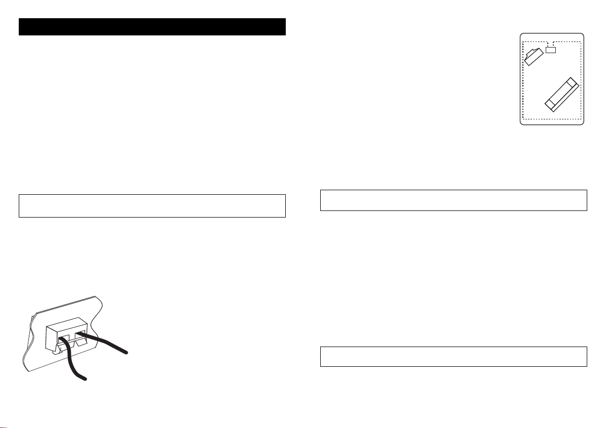
No sound. • Re-check all connections.
Check diagrams.
• Amplifier not switched on. Switch on at mains socket.
Press mains switch. Check Blue LED light is on.
• Microphone not plugged in or other audio source not
connected.
• Hearing aid not on “T/MT” or “T” facility not working.
Low sound. • Microphone too far from sound.
• Loop cable wired incorrectly.
• Volume control set too low. Turn up volume on amplifier.
• Radio or TV volume set too low. Turn up volume on Radio
or TV.
• Line Input Level Control too low. Turn up.
Distorted sound • Loop Volume control too high. (Loop Level indicator on)
Turn volume down.
• Radio or TV volume set too high.
Turn down volume on Radio or TV.
• Line Input Level Control too high.Turn down.
• Move microphone away from loud speaker.
• Microphone plug/lead damaged.
Background noise • If noise remains when loop amplifier is turned off but
hearing aid is still on “T”, this is interference caused by
other equipment such as TV, fluorescent lights or dimmer
switches. With the loop amplifier turned off and the
hearing aid still on “T” turn items off in turn until the
noise goes away.
• If noise stops when the loop amplifier is turned off there
may be a fault in the system or microphone lead or noise
is being picked up by the microphone.
(hum or buzz)
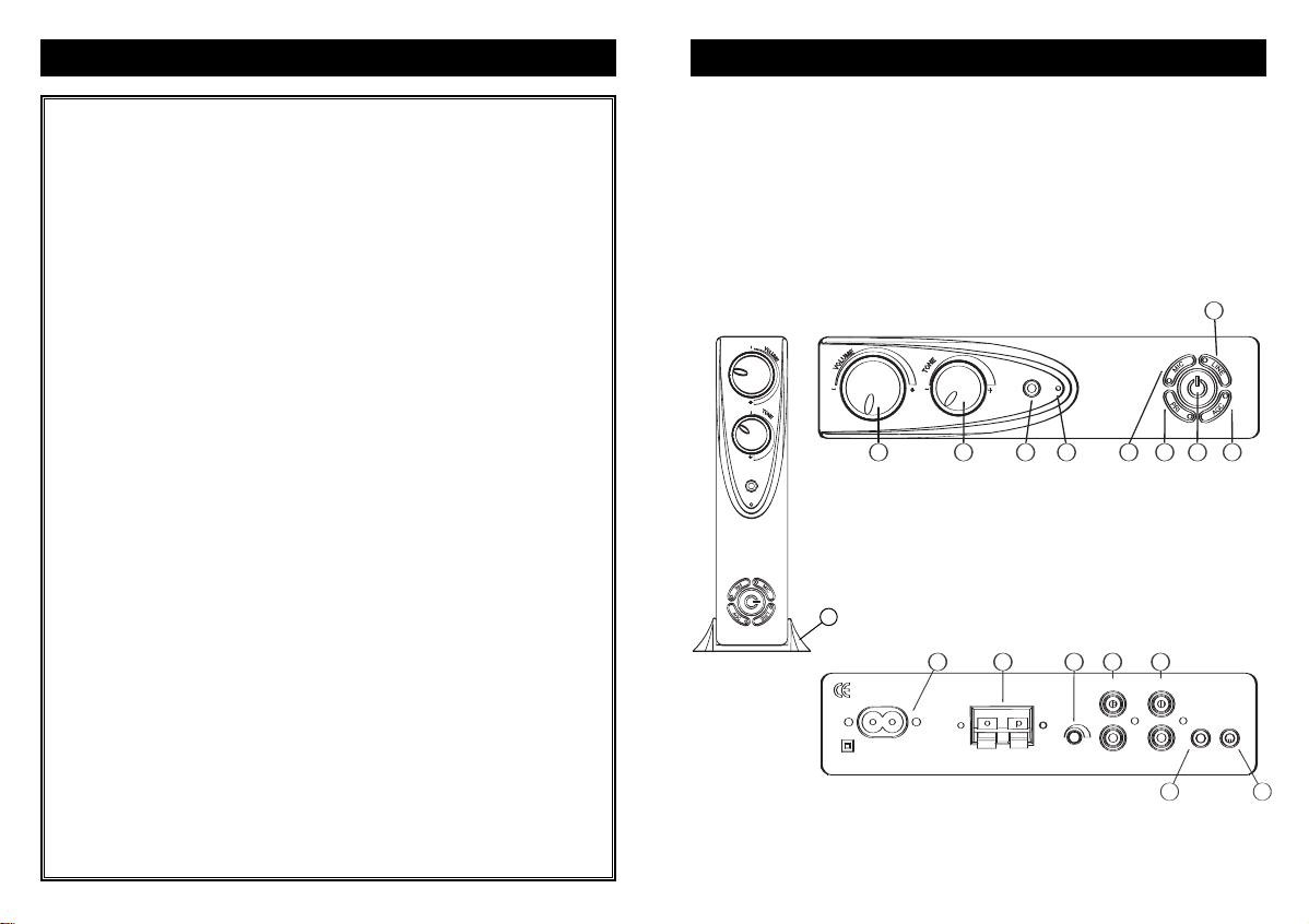
FUNCTION BUTTONS
All the function buttons are operated in the
same way. Press the button to turn on, the
associated led will light. Press the button
again to turn off and the led will go out.
MIC microphone sensitivity (5)
This function adjusts the sensitivity of the
microphone channel.
This can be useful if the room is noisy as the background sounds can be
reduced. It can also be used to balance the system when used in
conjunction with line inputs.
PRI priority function (6)
If a microphone is plugged into socket B (15) and this function is on,
then the any sound received by it will override all the other sounds in the
loop system. This can be useful when monitoring a doorbell or
telephone bell or if someone wants to attract the attention of the hearing
aid user through the loop.
Power (7)
Turns the amplifier on and off.
AGC Automatic Gain Control (8)
When activated this function will limit the loop output to a maximum level
set by the volume control.
This can be useful to stop the volume going above a set level that the
user might find annoying, such as during commercial breaks on TV.
LINE Line Input selector (9)
Useful if you want to listen to either a television or a sound system
without changing leads. Allows the selection of the line input signal from
either channel A or B but not both. If the light is offchannel A is
selected. If the light is on channel B is selected.
LA215 Instruction book 12/10/07 07:42 Page 11