Satellite Systems Corporation 3430 BTR-L User manual

Model 3430 BTR-L
L-Band Beacon Tracking Receiver
Version 4A15 Firmware
Instruction Manual

Model 3430BTR-L -- L-Band Beacon Tracking Receiver -- Version 4A15 Firmware -- Sept 2008 -- Page 1
Satellite Systems Corporation – 101 Malibu Drive – Virginia Beach – Virginia -23452 – USA
www.satsyscorp.com – 1.757.463.3553 PHONE – 1.757.463.3891 FAX
Model 3430 BTR-L
L-Band Beacon Tracking Receiver
A tracking receiver for antenna step tracking or automatic uplink power control
1. Functional Description
a. Satellite Systems (SSC) Model 3430BTR-L is a fully agile satellite tracking receiver designed to provide a linear
DC reference voltage proportional to the received signal level of a satellite beacon or other SCPC carrier. The
3430BTR-L has a pre-detection bandwidth of 50 kHz and a minimum frequency step size of 10 kHz. Carrier
frequency selection can be made of any carrier within the 1370 MHz band of the satellite. The frequency, RF Input
reference level, baud rate and serial communication format are controlled through front panel controls. The
frequency and RF Input reference level may also be controlled through a remote serial link.
b. With our enhanced Monitor and Control the unit can be connected by Ethernet, RS-232 and RS-485/422. All
ports are available on the unit, and the front panel controls will select which of the three ports are currently active.
Only the active port will respond to data.

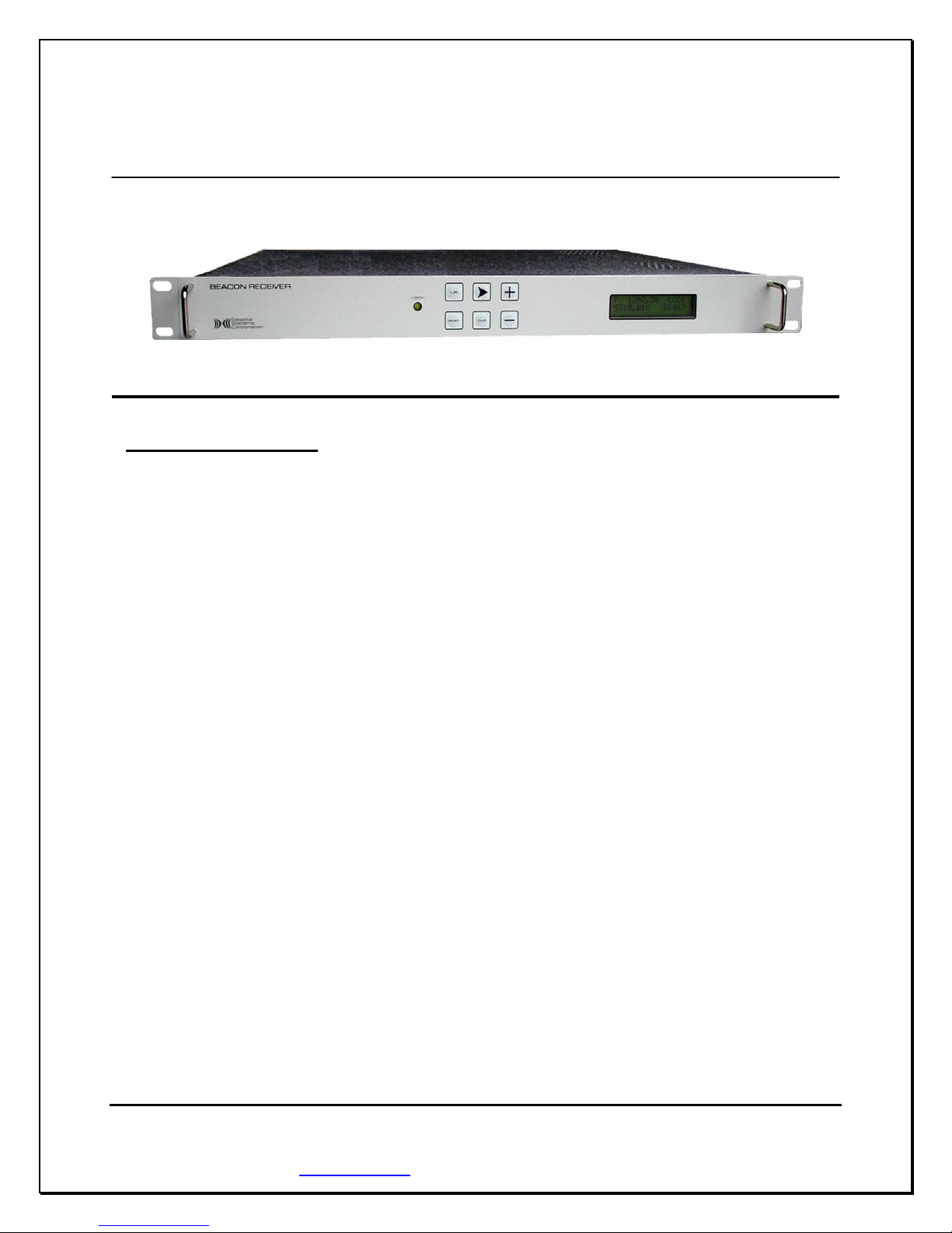
Model 3430BTR-L -- L-Band Beacon Tracking Receiver -- Version 4A15 Firmware -- Sept 2008 -- Page 2
Satellite Systems Corporation – 101 Malibu Drive – Virginia Beach – Virginia -23452 – USA
www.satsyscorp.com – 1.757.463.3553 PHONE – 1.757.463.3891 FAX
Table of Contents
Unit Specifications (2) ......................................................................................................................................... Pg. 3
Front Panel Facilities
Display (3.1) .......................................................................................................................................................... Pg. 4
Keypad Functions (3.2) ................................................................................................................................... Pg. 4 - 5
Rear Panel Facilities
Rear Mounted Terminal Plug (4.1) ........................................................................................................................ Pg. 6
RF Input Connector (4.2) ....................................................................................................................................... Pg. 7
Network Connector (4.3) ....................................................................................................................................... Pg. 7
Programming Procedures
Selecting Local or Remote Mode (5.1) .................................................................................................................. Pg. 8
Setting Carrier Frequency (5.2) ............................................................................................................................. Pg. 8
Adjusting Reference Level (5.3) ............................................................................................................................ Pg. 9
AFC Status (5.4) .................................................................................................................................................... Pg. 9
Selecting Monitor and Control Parameters (5.5) ................................................................................................... Pg. 9
Selecting Network, RS-232, or RS-485 (5.5.1) ..................................................................................... Pg. 10
Selecting RS-485 Address (5.5.2) ......................................................................................................... Pg. 10
Selecting Baud Rate (5.5.3) ................................................................................................................... Pg. 10
Remote Operations
RS-232 Operation (6.1) ....................................................................................................................................... Pg. 11
Polling the 3430 in RS-232 (6.1.1) ........................................................................................................ Pg. 11
Changing Frequency and Reference Level in RS-232 (6.1.2) ....................................................... Pg. 12 - 13
RS-485 Operation (6.2) ....................................................................................................................................... Pg. 14
Polling the 3430 in RS-485 (6.2.1) ........................................................................................................ Pg. 14
Changing Frequency and Reference Level in RS-485 (6.2.2) ....................................................... Pg. 14 - 15
Network Operation (6.3) ...................................................................................................................................... Pg. 16
Polling the 3430 in Network (6.3.1) ...................................................................................................... Pg. 16
Changing Frequency and Reference Level in Network (6.3.2) ..................................................... Pg. 16 - 17
System Alignment Procedure (7) ...................................................................................................................... Pg. 18
System Alignment Work Sheet (8) ...................................................................................................................... Pg. 19
Troubleshooting Guide (9) ........................................................................................................................ Pg. 20 - 21
Detailed Monitor and Control Protocol (10) ................................................................................................... Pg. 22
Graphical User Interface (11) ........................................................................................................................... Pg. 31
Computer Setup (Appendix A) .......................................................................................................................... Pg. 33
Router Setup (Appendix B) ............................................................................................................................... Pg. 36
IP and Port Configuration (Appendix C) ......................................................................................................... Pg. 39
Sales Terms and Conditions ............................................................................................................................. Pg. 45
Repair and Warranty Policies .................................................................................................................. Pg. 49 - 50
Regulatory Information .................................................................................................................................... Pg. 51
Factory Test Data .............................................................................................................................................. Pg. 52

Model 3430BTR-L -- L-Band Beacon Tracking Receiver -- Version 4A15 Firmware -- Sept 2008 -- Page 3
Satellite Systems Corporation – 101 Malibu Drive – Virginia Beach – Virginia -23452 – USA
www.satsyscorp.com – 1.757.463.3553 PHONE – 1.757.463.3891 FAX
2. Model 3430-L BTR Unit Specifications
Input Frequency ................................................................................................................................. 930 to 2300 MHz
Input Level ......................................................... -100 dBm minimum; -40 dBm maximum for full tracking range
Input Impedance ................................................................................................................................................ 50 ohm
(Optional 75 ohm with ‘F’ type adapter)
Frequency Selection ....................................................................... Local or Remote over 1370 MHz on 10 kHz steps
Tracking Threshold ................................................................... 4 dB C/N for acquisition, < 1 dB C/N for carrier lock
Alarm ........................................................................................................ Lock/Alarm display, Form-C relay contacts
Noise Bandwidth ............................................................................................................................................... 50 kHz
Tracking Response ........................................................................... 0 to 10.0 VDC for a 20 dB change of input level
AFC ................................................................................................................................................................. ±25 kHz
MECHANICAL
Front Panel Display ............ Frequency, Carrier Lock or Alarm, RF Input Reference level, DC Output Voltage, AFC
Input Connector ............................................................................................................................. N-Female (50 ohm)
(Optional 75 ohm with ‘F’ type adapter)
Output Connector .......................................................................................................... Modular connector (provided)
MONITOR AND CONTROL
RS-232/422/485 ...................................................................................................................... DB-9 Female Connector
Ethernet TCP/IP Network ................................................................................................................... RJ-45 Connector
DIMENSIONS ............................................................................................ Standard 19" rack mount, 1 RU, 16" deep
POWER ............................................................................. 90-260 VAC, 47-63 Hz, auto-sensing, 45 watts maximum

Model 3430BTR-L -- L-Band Beacon Tracking Receiver -- Version 4A15 Firmware -- Sept 2008 -- Page 4
Satellite Systems Corporation – 101 Malibu Drive – Virginia Beach – Virginia -23452 – USA
www.satsyscorp.com – 1.757.463.3553 PHONE – 1.757.463.3891 FAX
3. Front Panel Facilities
3.1 DISPLAY
3.1.1 Receive Frequency
The frequency to which the 3430 is tuned is displayed in the upper left corner of the display.
3.1.2 Carrier Lock or Alarm Status
When the 3430 is locked to a carrier, the LOCK LED on the front panel will light green. When the unit is
in alarm, the LOCK LED will be extinguished.
3.1.3 VDC Output
The tracking reference DC level output from the 3430 will be displayed in the lower right corner of the
display.
3.1.4 RF Input Reference Level
The RF Input Reference Level to the 3430 may be adjusted to the receiver’s linear range. A number
between -100.0dB and -40.0dB, which represents the input level setting to achieve 7.5 Volts DC output, is
displayed in the lower left corner of the display.
3.1.5 AFC Status
The AFC status, L, H, N, or — is displayed in the upper right corner of the display. (Sec 5.4)
3.2 KEYPAD FUNCTIONS
3.2.1 L/R Activates LOCAL /REMOTE SET MODE
3.2.2 ➤Activates MONITOR AND CONTROL options.
Moves cursor right in FREQUENCY SET MODE.
Select NETWORK.
3.2.3 CUR Activates FREQUENCY SET MODE.
Performs EXIT functions.
3.2.4 ✛Increases RF Input Reference Level to make the unit more sensitive to allow for weaker
signals.
Change FREQUENCY up.
Select BAUD RATE up.
Select RS-232.
Select ADDRESS up.

Model 3430BTR-L -- L-Band Beacon Tracking Receiver -- Version 4A15 Firmware -- Sept 2008 -- Page 5
Satellite Systems Corporation – 101 Malibu Drive – Virginia Beach – Virginia -23452 – USA
www.satsyscorp.com – 1.757.463.3553 PHONE – 1.757.463.3891 FAX
3.2.5 —Decreases RF Input Reference Level to make the unit less sensitive to allow for stronger
signals.
Change FREQUENCY down.
Select BAUD RATE down.
Select RS-485.
Select ADDRESS down.
3.2.6 RESET Soft system reboot.

Model 3430BTR-L -- L-Band Beacon Tracking Receiver -- Version 4A15 Firmware -- Sept 2008 -- Page 6
Satellite Systems Corporation – 101 Malibu Drive – Virginia Beach – Virginia -23452 – USA
www.satsyscorp.com – 1.757.463.3553 PHONE – 1.757.463.3891 FAX
4. Rear Panel Facilities
4.1 Rear Mounted Terminal Plug (provided)
1 - N/C Normally closed relay contact. Closed with respect to common when unit is
LOCKED to beacon.
2 - N/O Normally open relay contact. Open with respect to common when unit is LOCKED
to beacon.
3 – COM Alarm relay common
4 - N/A Reserved
5 - PWR-2 Jumper PWR-1 to PWR-2 to provide +24 VDC on the L-band input center
conductor
6 - PWR-1 Jumper PWR-1 to PWR-2 to provide +24 VDC on the L-band input center
conductor
7 – GND Signal Ground
8 - SS Provides a DC reference proportional to the received signal input level. This DC
level changes approximately 0.5 volts for a one dB input signal level change over a
0 to 10.0 VDC range. Normal; +7.5 VDC for -65 dBm input.

Model 3430BTR-L -- L-Band Beacon Tracking Receiver -- Version 4A15 Firmware -- Sept 2008 -- Page 7
Satellite Systems Corporation – 101 Malibu Drive – Virginia Beach – Virginia -23452 – USA
www.satsyscorp.com – 1.757.463.3553 PHONE – 1.757.463.3891 FAX
4.2 RF Input Connector
N-type female connector with +24 VDC on center conductor when PWR-1 and PWR-2 are jumpered
together. Connects directly to the PLL BDC or LNB for 930 to 2300 MHz operation.
*NOTE: If the 3430 is supplied with a BDC or LNB, the +24 VDC on the center conductor may have been
activated internally at the factory.
Refer to the TEST DATA SHEET for verification.
!! Safety Notice !!
The socket-outlet shall be installed near the
equipment and shall be easily accessible.
4.3 Ethernet Connector
RJ-45 type female connector for Monitor and Control Ethernet connectivity.

Model 3430BTR-L -- L-Band Beacon Tracking Receiver -- Version 4A15 Firmware -- Sept 2008 -- Page 8
Satellite Systems Corporation – 101 Malibu Drive – Virginia Beach – Virginia -23452 – USA
www.satsyscorp.com – 1.757.463.3553 PHONE – 1.757.463.3891 FAX
5. Programming Procedures
The 3430 Version 4A15 Firmware offers accessibility to all operating parameters quickly, and easily. Carrier
frequency, RF Input Reference Level, local or remote operation, NETWORK, RS-232, RS-485, RS-485 addressing
and baud rates can all be changed with just a few button clicks.
5.1 SELECTING LOCAL OR REMOTE MODE
To change mode of operation press and release L/R .
When the 3430 is in LOCAL mode, the display will show:
Go to Remote
Mode ? + = Yes
Press and release ✛. The 3430 will switch to REMOTE operation mode.
Pressing any other key will exit mode.
See Sec.5.5 for M&C options and operations.
*NOTE: When the 3430 is in remote mode only the L/R and RESET buttons are active.
The same procedure is used to switch from REMOTE to LOCAL.
Press and release L/R .
When the 3430 is in REMOTE mode, the display will show:
Go to Local
Mode ? + = Yes
Press and release ✛. The 3430 will switch to LOCAL mode.
Pressing any other key will exit mode.
5.2 SETTING CARRIER FREQUENCY
To set the FREQUENCY on the 3430, place unit in LOCAL mode. Press and release CUR to activate
FREQUENCY SET mode.
The display will show:
Freq Set
F = 1555.50
The cursor will highlight the digit to be changed.
To raise the value press ✛, To lower the value press — .
To move the cursor right press ➤, To move the cursor left press L/R .
The roll-over feature will automatically change the digits left of the cursor.
When carrier frequency has been selected press CUR to exit.

Model 3430BTR-L -- L-Band Beacon Tracking Receiver -- Version 4A15 Firmware -- Sept 2008 -- Page 9
Satellite Systems Corporation – 101 Malibu Drive – Virginia Beach – Virginia -23452 – USA
www.satsyscorp.com – 1.757.463.3553 PHONE – 1.757.463.3891 FAX
5.3 ADJUSTING RF INPUT REFERENCE LEVEL
To increase RF Input Reference Level sensitivity, press and hold ✛.
To decrease RF input Reference Level sensitivity, press and hold — .
5.4 AFC STATUS
The AFC STATUS shows the location of the beacon signal frequency relative to the center frequency selected on
the 3430 within the AFC range.
When the center frequency selected on the 3430 is within 15 kHz of the beacon signal frequency, the AFC
STATUS will read Nfor Normal.
If the center frequency selected on the 3430 is greater than 15 kHz above the beacon signal frequency, the AFC
STATUS will read Lfor Low.
If the center frequency selected on the 3430 is greater than 15 kHz below the beacon signal frequency, the AFC
STATUS will read Hfor High.
When the 3430 is in alarm, meaning there is no carrier detected, the AFC STATUS will read — for Alarm.
Adjustments can be made accordingly (sec 5.2).
5.5 SELECTING MONITOR and CONTROL PARAMETERS
Monitor and Control parameters are accessed through a series of sub-screens. Selection of baud rate, mode, and
RS-485 addressing requires just a few button clicks. With our expanded RS-485 addressing Version 4A15
Firmware, numerous multi-unit combinations and large applications are easily supported.
The model 3430 now supports TCP/IP Network operations. Below is the default Network setup that every unit is
shipped with :
Unit IP Address 192.168.1.200
Unit IP Port number 8080
Unit IP Subnet mask 255.255.255.0
All ports are available on the unit, and the front panel controls will select which of the three ports are currently
active.
To begin Monitor and Control programming, place the 3430 in LOCAL mode (sec.5.1). Press and release ➤to
activate SUB-SCREEN #1:

Model 3430BTR-L -- L-Band Beacon Tracking Receiver -- Version 4A15 Firmware -- Sept 2008 -- Page 10
Satellite Systems Corporation – 101 Malibu Drive – Virginia Beach – Virginia -23452 – USA
www.satsyscorp.com – 1.757.463.3553 PHONE – 1.757.463.3891 FAX
5.5.1 SELECTING MODE (RS-232, RS-485, or Network)
The display will show:
Press ✛RS-232
— RS-485 ➤Net
5.5.1a Selecting RS-232
To select RS-232, press and release ✛.
The 3430 will automatically continue to the BAUD RATE screen.
5.5.1b Selecting RS-485
To select RS-485, press and release — .
This will activate RS-485 ADDRESS screen.
5.5.1c Selecting Network
To select Network, press and release ➤.
The 3430 will automatically return to the LOCAL mode screen.
5.5.2 SELECTING RS-485 ADDRESSING
The display will show:
M&C Addr = 01
Cur to Exit
RS-485 ADDRESSING OPTIONS are 01 thru FF hexadecimal.
To raise the address number, press and hold ✛.
To lower the address number, press and hold — .
When the correct address is displayed, press and release CUR.
The 3430 will automatically continue to the BAUD RATE screen.
*NOTE: Due to addressing conflicts, addresses 0A and 0D are invalid and cannot be used.
5.5.3 SELECTING BAUD RATE
The display will show:
Baud 1200
Cur to Exit
BAUD RATE choices are 1200, 2400, 4800, 9600, and 19200.
To increase BAUD RATE press and release ✛.
To decrease BAUD RATE press and release — .
When the correct BAUD RATE is displayed, press and release CUR.
The 3430 will automatically return to the LOCAL mode screen.

Model 3430BTR-L -- L-Band Beacon Tracking Receiver -- Version 4A15 Firmware -- Sept 2008 -- Page 11
Satellite Systems Corporation – 101 Malibu Drive – Virginia Beach – Virginia -23452 – USA
www.satsyscorp.com – 1.757.463.3553 PHONE – 1.757.463.3891 FAX
6 Remote Operations
The serial protocol for the 3430 shall remain the same for any of the selected baud rates and must be followed.
Example:
1200,8,N,1
1200 baud, eight data bits, no parity, 1 stop bit.
6.1 RS-232 OPERATION
6.1.1 POLLING THE 3430 IN RS-232
The 3430 can be polled in either LOCAL or REMOTE mode.
To query a status report from the 3430, send the command string:
F<CR>
That is, the ASCII letter “F” followed by a carriage return.
The unit will respond with:
FREQ=(receive frequency), REF=(reference level), SS=(signal strength voltage), L (lock) or A (alarm)
Example:
FREQ=1555.50,REF=-65.0dB,SS=750,L<CR>

Model 3430BTR-L -- L-Band Beacon Tracking Receiver -- Version 4A15 Firmware -- Sept 2008 -- Page 12
Satellite Systems Corporation – 101 Malibu Drive – Virginia Beach – Virginia -23452 – USA
www.satsyscorp.com – 1.757.463.3553 PHONE – 1.757.463.3891 FAX
6.1.2 CHANGING FREQUENCY AND REFERENCE LEVEL in RS-232
To change the FREQUENCY and REFERENCE LEVEL setting on the 3430 in RS-232 send the following
command string :
F space frequency in MHz space frequency in kHz space
Reference level <CR>
Example:
F 1555 50 -65.0<CR>
The 3430 will respond with:
FREQ=1555.50,REF=-65.0dB,SS=750,L<CR>
Valid command options are as follows:
Frequency in MHz = 930 to 2300 MHz in 1 MHz increments
Frequency in kHz = 00 to 99 in 10 kHz increments
Ref = a reference level between -100.0 and -40.0 in 0.5 dB steps.

Model 3430BTR-L -- L-Band Beacon Tracking Receiver -- Version 4A15 Firmware -- Sept 2008 -- Page 13
Satellite Systems Corporation – 101 Malibu Drive – Virginia Beach – Virginia -23452 – USA
www.satsyscorp.com – 1.757.463.3553 PHONE – 1.757.463.3891 FAX
NOTES:
All ports are available on the unit, and the front panel controls will select which of the three ports are currently
active. Only the active port will respond to data.
Do not attempt to use a Linefeed character, as the string will not be accepted. Use a Carriage Return only to
terminate the string.
Reference Level dB values must contain the ‘-‘ (minus sign) and the ‘.’ (Decimal point) at the indicated locations. If
these are misplaced or missing, the string will be rejected.
Reference Level dB values must be in multiples of 0.5 dB. Therefore the Reference Level field must end in a ‘0' or
‘5'. Other values will be rejected and will return a REF STEP ERROR.
The entire command string must be transmitted in all cases; to change frequency, Reference Level or both. If an
invalid command is sent the 3430 will respond with one of the following:
FREQ ERROR
REF ERROR
BOTH ERROR
REF STEP ERROR
COMM ERROR
*NOTE: The 3430 must be in REMOTE mode (sec.5.1) to respond to command strings. When the 3430 is in
LOCAL mode, and a command string is sent, the unit will respond with a current status reading.
Example:
LOCAL ONLY
FREQ=1555.50,REF=-65.0dB,SS=750,L<CR>

Model 3430BTR-L -- L-Band Beacon Tracking Receiver -- Version 4A15 Firmware -- Sept 2008 -- Page 14
Satellite Systems Corporation – 101 Malibu Drive – Virginia Beach – Virginia -23452 – USA
www.satsyscorp.com – 1.757.463.3553 PHONE – 1.757.463.3891 FAX
6.2 RS-485 Operation
5. Gnd
6.2.1 POLLING THE 3430 IN RS-485
To query a status report from the 3430 in RS-485 mode, send the command string:
Hex address <CR>
That is, the address value you have assigned to the 3430 (sec. 5.5.3) followed by a carriage return in hexadecimal.
The unit will respond with:
ADDR=(hex address), FREQ=(receive frequency), REF=(reference level), SS=(signal strength voltage),
L (lock) or A (alarm)
Example:
ADDR=01,FREQ=1555.50,REF=-65.0dB,SS=750,L<CR>
6.2.2 CHANGING THE FREQUENCY AND GAIN IN RS-485
To change the FREQUENCY and REFERENCE LEVEL setting on the 3430 in RS-485 send the following
command string :
Hex address space frequency in MHz space
Frequency in kHz space reference level <CR>
Example:
^A 1555 50 -65.0 <CR>
The 3430 will respond with:
ADDR=01,FREQ=1555.50,REF=-65.0dB,SS=750,L<CR>
Valid command options are as follows:
Hex address = 01 through FF
Frequency in MHz = 930 to 2300 MHz in 1 MHz increments
Frequency in kHz = 00 to 99 in 10 kHz increments
Ref = a reference level between -100.0 and -40.0 in 0.5 dB steps.

Model 3430BTR-L -- L-Band Beacon Tracking Receiver -- Version 4A15 Firmware -- Sept 2008 -- Page 15
Satellite Systems Corporation – 101 Malibu Drive – Virginia Beach – Virginia -23452 – USA
www.satsyscorp.com – 1.757.463.3553 PHONE – 1.757.463.3891 FAX
NOTES:
All ports are available on the unit, and the front panel controls will select which of the three ports are currently
active. Only the active port will respond to data.
Do not attempt to use a Linefeed character, as the string will not be accepted. Use a Carriage Return only to
terminate the string.
Reference Level dB values must contain the ‘-‘ (minus sign) and the ‘.’ (Decimal point) at the indicated locations. If
these are misplaced or missing, the string will be rejected.
Reference Level dB values must be in multiples of 0.5 dB. Therefore the Reference Level field must end in a ‘0' or
‘5'. Other values will be rejected and will return a REF STEP ERROR.
The entire command string must be transmitted in all cases; to change frequency, Reference level or both. If an
invalid command is sent the 3430 will respond with one of the following:
FREQ ERROR
REF ERROR
BOTH ERROR
REF STEP ERROR
COMM ERROR

Model 3430BTR-L -- L-Band Beacon Tracking Receiver -- Version 4A15 Firmware -- Sept 2008 -- Page 16
Satellite Systems Corporation – 101 Malibu Drive – Virginia Beach – Virginia -23452 – USA
www.satsyscorp.com – 1.757.463.3553 PHONE – 1.757.463.3891 FAX
6.3 Network Operation
The 3430 is equipped with TCP/IP interface for raw TCP/IP communications.
Communications can be established using a TCP/IP port to connect to our Graphical User Interface that is supplied
with the unit.
Alternatively, you may use Hyperterminal or similar terminal program to communicate with the unit.
6.3.1 POLLING THE 3430 IN NETWORK MODE
The 3430 can be polled in either LOCAL or REMOTE mode.
To query a status report from the 3430, send the TCI/IP command string:
F<CR>
That is, the ASCII letter “F” followed by a carriage return.
The unit will respond with the TCP/IP reply string:
FREQ=(receive frequency), REF=(reference level), SS=(signal strength voltage), L (lock) or A (alarm)
Example:
FREQ=1555.50,REF=-65.0dB,SS=750,L<CR>
6.3.2 CHANGING FREQUENCY AND REFERENCE LEVEL IN NETWORK MODE
To change the FREQUENCY and REFERENCE LEVEL setting on the 3430 in the Network mode, send the
following TCP/IP command string :
F space frequency in MHz space frequency in kHz space
Reference level <CR>
Example:
F 1555 50 -65.0<CR>
The 3430 will respond with the TCP/IP reply string:
FREQ=1555.50,REF=-65.0dB,SS=750,L<CR>
Valid command options are as follows:
Frequency in MHz = 930 to 2300 MHz in 1 MHz increments
Frequency in kHz = 00 to 99 in 10 kHz increments
Ref = a reference level between -100.0 and -40.0 in 0.5 dB steps.

Model 3430BTR-L -- L-Band Beacon Tracking Receiver -- Version 4A15 Firmware -- Sept 2008 -- Page 17
Satellite Systems Corporation – 101 Malibu Drive – Virginia Beach – Virginia -23452 – USA
www.satsyscorp.com – 1.757.463.3553 PHONE – 1.757.463.3891 FAX
NOTES:
All ports are available on the unit, and the front panel controls will select which of the three ports are currently
active. Only the active port will respond to data.
The model 3430 supports TCP/IP Network operations. Below is the default Network setup that each unit is shipped
with :
Unit IP Address 192.168.1.200
Unit IP Port number 8080
Unit IP Subnet mask 255.255.255.0
These settings can be changed by the User. Refer to Appendix C on IP and Port Configuration.
Do not attempt to use a Linefeed character, as the string will not be accepted. Use a Carriage Return only to
terminate the string.
Reference Level dB values must contain the ‘-‘ (minus sign) and the ‘.’ (Decimal point) at the indicated locations. If
these are misplaced or missing, the string will be rejected.
Reference Level dB values must be in multiples of 0.5 dB. Therefore the Reference Level field must end in a ‘0' or
‘5'. Other values will be rejected and will return a REF STEP ERROR.
The entire command string must be transmitted in all cases; to change frequency, Reference Level or both. If an
invalid command is sent the 3430 will respond with one of the following:
FREQ ERROR
REF ERROR
BOTH ERROR
REF STEP ERROR
COMM ERROR
*NOTE: The 3430 must be in REMOTE mode (sec.5.1) to respond to command strings. When the 3430 is in
LOCAL mode, and a command string is sent, the unit will respond with a current status reading.
Example:
LOCAL ONLY
FREQ=1555.50,REF=-65.0dB,SS=750,L<CR>

Model 3430BTR-L -- L-Band Beacon Tracking Receiver -- Version 4A15 Firmware -- Sept 2008 -- Page 18
Satellite Systems Corporation – 101 Malibu Drive – Virginia Beach – Virginia -23452 – USA
www.satsyscorp.com – 1.757.463.3553 PHONE – 1.757.463.3891 FAX
7. System Alignment Procedure
7.1
Install the recommended cable between the PLL BDC or LNB and the 3430.
7.2
Plug the AC cord, which is provided with the unit, into the rear mounted receptacle. Plug the male end of the power
cord into a suitable 90-260 VAC, 47-63 Hz power outlet. The BTR's power supply automatically detects AC input
voltage.
7.3
Tune the 3430 to the beacon frequency. (Sec. 4.2)
7.4
Adjust the 3430 reference level to -100.0dB. (Sec. 4.3)
7.5
If the antenna system is properly aligned to the appropriate satellite and polarity, the front panel LOCK LED will
become illuminated, and the AFC STATUS will read H, L or N (sec.5.4). Observe the REFERENCE LEVEL value
at the lower left corner of the display. Adjust the REFERENCE LEVEL (Sec. 5.3) for a DC level as nearly as
possible to + 7.50 Volts. This sets the receiver to it’s most linear range.
7.6
If the antenna system is properly aligned to the appropriate satellite and polarity and the front panel LED fails to
show LOCK, try tuning the 3430 in 10 kHz steps above and below the beacon frequency (sec.5.2). You may find
the beacon is slightly off frequency or minor frequency uncertainty within your link.
7.7
The antenna can be optimally aligned while monitoring this voltage for a maximum reading. If necessary readjust
the REFERENCE LEVEL to achieve +7.50 VDC. (Sec.5.3)
The following page is a work sheet for your records.

Model 3430BTR-L -- L-Band Beacon Tracking Receiver -- Version 4A15 Firmware -- Sept 2008 -- Page 19
Satellite Systems Corporation – 101 Malibu Drive – Virginia Beach – Virginia -23452 – USA
www.satsyscorp.com – 1.757.463.3553 PHONE – 1.757.463.3891 FAX
8. System Alignment Work Sheet
Model 3430-L BTR
Serial Number __________________________ Date _____________________________
Input Signal Output
Level dBm Volts DC
- 60 _______________________
- 61 _______________________
- 62 _______________________
- 63 _______________________
- 64 _______________________
- 65 _______________________
- 66 _______________________
- 67 _______________________
- 68 _______________________
- 69 _______________________
- 70 _______________________
- 71 _______________________
- 72 _______________________
- 73 _______________________
- 74 _______________________
- 75 _______________________
- 76 _______________________
- 77 _______________________
- 78 _______________________
- 79 _______________________
- 80 _______________________
Table of contents