1. General Information
.............................................................................................
...............................................................................
.............................................................................................
1-1. Introduction
1-2. Proper use and operation
1-3. Safety notes
2
3
4
2. Contents
...................................................................................
...........................................................................................
2-1. Components bundle
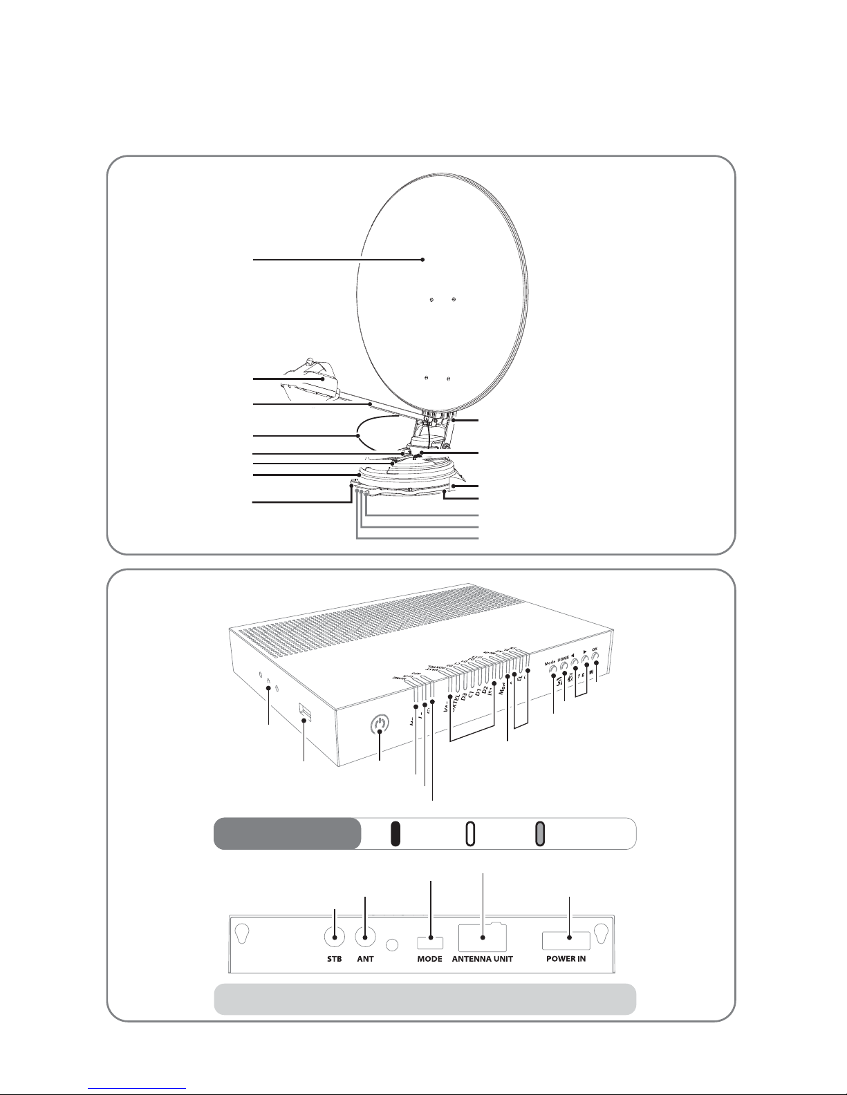
2-2. Name of parts
5
6
9. Caravan/Motorhome installation
..................................................................
..............................................................................
...............................................................................................
......................................................................................
.................................................................................................
9-1. Required space for the SatKing ORBIT
9-2. Equipment for installation
9-3. Installation
9-4. Battery connection
9-5. Options
16
17
17
21
22
6. Extra functions
...........................................................................................
............................................................................................
.......................................................................................
......................................................................................
6-1. Error message
6-2. Factory reset
6-3. Software upgrade
6-4. Advanced settings
12
12
12
13
.........................................................................................
..................................................................................
..................................................................
............................................................................
5-1. Get ready to use
5-2. Searching the satellite
5-3. Back to HOME position & Turning o
5-4. STB power detection On/O
11
11
11
11
8. Specications
...............................................................................................
............................................................................................
8-1. Dimension
8-2. Specications
15
15
7. Troubleshooting ................................................................................ 14
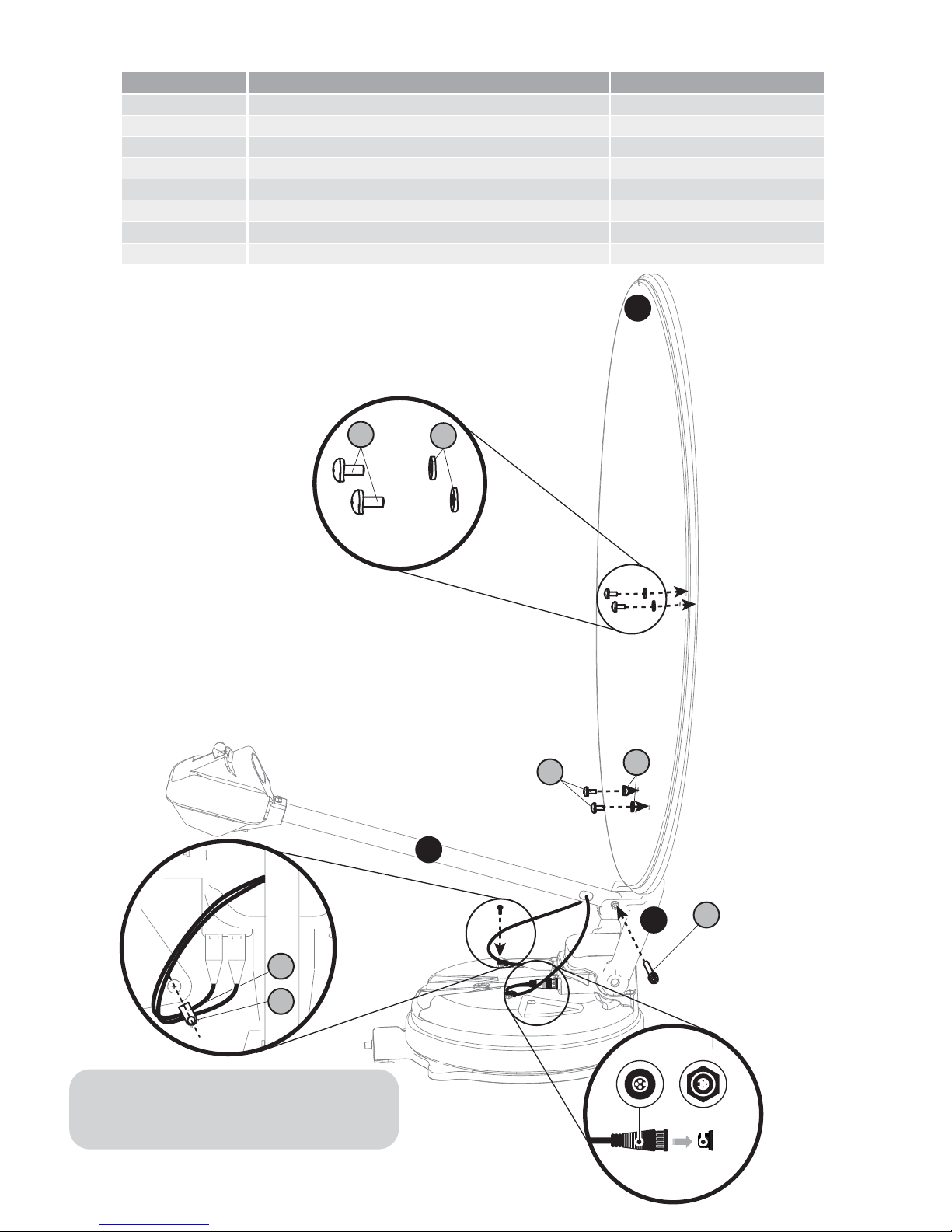
3. How to assemble dish (reector)
4. Connection diagram
5. Functional description
.......................................................
...........................................................................
.......................................................................
7
9
10
Contents