Intellian V60KA User manual

Marine Satellite Communication Antenna System
v60Ka
Installation and Operation Manual


Serial number of the product
This serial number will be required for the all troubleshooting or service inquiries.
© 2019 Intellian Technologies Inc. All rights reserved. Intellian and the Intellian
logo are trademarks of Intellian Technologies, Inc., registered in the U.S. and other
countries. The v-Series and the v60Ka are trademarks of Intellian Technologies, Inc.
Intellian may have patents, patent applications, trademarks, copyrights, or other
intellectual property rights covering subject matter in this document. Except as
expressly provided in any written license agreement from
Intellian, the furnishing of this document does not give you any license to these
patents, trademarks, copyrights, or other intellectual property. All other logos,
trademarks, and registered trademarks are the property of their respective owners.
Information in this document is subject to change without notice. Every effort has
been made to ensure that the information in this manual is accurate. Intellian is not
responsible for printing or clerical errors.
Doc. No. UM-N3-190207-V1.4
v60Ka– Marine Satellite Communication System
4
THIS WAY UP
• Place the boxes/crates on the oor noting the direction of the arrow.
FRAGILE
• Since the Radome is fragile, handle it with care. Do not apply excessive pressure or shock.
These may cause surface cracking or other damage.
DO NOT STACK
• Do not stack boxes/crates as there is a risk boxes/crates may fall and be damaged.
KEEP DRY
• Always make sure the antenna is stored on a dried oor.
• The antenna can withstand ordinary rain. However it water resistance cannot be guaranteed
if submerged.
• Keep the antenna in dried place for sufcient ventilation. Do not store the antenna wrapped
in a tarp, tent, vinyl, and others.
General Precautions
Before you use the antenna, make sure that you have read and understood all safety requirements.

5
Table of Contents
Table of Contents
Certifications 8
Introduction 12
Intellian v60Ka Introduction 12
Intellian v60Ka Features 13
System Conguration 14
Installing Antenna 15
System Package 15
Antenna Unit 16
ACU (Antenna Control Unit) 17
Installation Kit 18
Planning the Installation 19
Selection of Antenna Installation Site 19
Congure Radiation Hazard/Block Zones 20
RF Hazard Precautions 20
System Cables 21
Power Requirement 21
Tools Required for Installation 22
Antenna Installation 23
Unpacking Wooden Crate of v60Ka 23
Antenna Dimensions 27
Antenna Mounting Templates 28
Mast Design Recommendation 30
Position Radome 31
Mounting Radome 32
RF Cable Connections 32
Installing ACU 34
Mounting the ACU 34
19” Rack Mount Type 34
Table Mount Type 34
ACU Dimensions 35
Gyrocompass Connection 36
Connecting System with Gyrocompass 36
Recommended Cable 36
Connecting System without Gyrocompass 37
PC to ACU Communication Setup 38
TCP/IP Connection 38

v60Ka– Marine Satellite Communication System
6
Wi-Fi Connection 39
One-touch Commissioning 41
ACU Connector Guide 42
Operating ACU 44
Introduction 44
Normal Mode 45
Startup 45
Monitoring Current Antenna Status 46
Setup Mode 49
Antenna Settings 50
Manual Search 50
Antenna Diagnostic Test 51
Satellite Settings 53
Load Satellite 53
System Settings 54
Set Location 54
Management 56
Key Lock 57
Using Aptus PC 58
Introduction 58
Hardware 58
Operating System and Software 58
Software Installation 59
PC to ACU Communication Setup 60
Starting Aptus® 60
Access ACU through Serial Communication 61
Access ACU through Network Communication (TCP/IP) 61
Auto Update 62
Toolbar Menus 63
System Property Status Dashboard 66
Work View Tabs 69
1. Antenna – Basic Info. 69
2. Antenna – Advanced Info. 70
3. Satellite 73
4. Graph View 75
5. Monitor 76
6. Diagnostic / Modem 77
7. GUI 79
8. Work View Functions 80
Using Aptus Web 84

7
Introduction 84
Main Page 85
Page Login 85
Top Menus 86
Dash Board & Information 87
Antenna Settings 89
Ship Setting 89
Antenna Position & Parameters 90
Tracking Setting 92
Modem Setting 93
Diagnostic 94
Library Setting 95
Firmware & Conguration 96
Antenna Firmware Upgrade 96
Antenna Log 99
Antenna Backup & Restore 101
Administration 102
Network Setting 102
User Management 105
iARM Upgrade 106
iARM Save & Reboot 108
Antenna Event Log 109
Modem Information 110
Technical Specification 111
Warranty 112

v60Ka– Marine Satellite Communication System
8
Doc Number IT14-DC0901-05
Intellian Technologies, Inc.
EMEA & APAC Headquarters
18-7, Jinwisandan-ro, Jinwi-myeon, Pyeongtaek-Si,
Si,
Gyeonggi-do 451-862, Korea
Tel: +82 2 511 2244
Intellian Technologies USA, Inc.
US Headquarters
9004 Research Drive
Irvine, CA 92618 USA
Tel: +1 949 727 4498
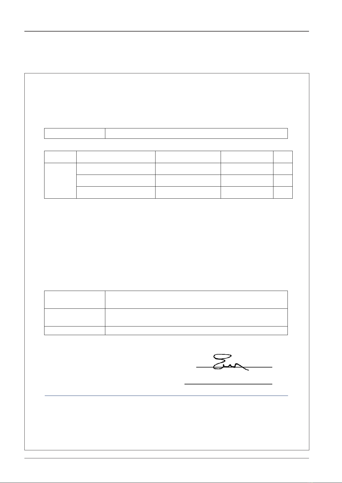
C-Tick Declaration of Conformity (DoC)
We, Intellian Technologies, Inc. located at 18-7, Jinwisandan-ro, Jinwi-myeon, Pyeongtaek-si, Gyeonggi-do 451-862,
Korea, declare that the product described below to which this declaration relates is in conformity with the
requirement of the Radio communications (ElectromagneticCompatibility) Standard 2008.
Product Information:
Product Name: Intellian v60Ka, 65cmKa-band Maritime Stabilized Antenna System
Test Result:
tluseRrebmuNtropeRtseTtseTdradnatS
AS/NZS CISPR 22
CISPR 22
EN 55022
Conducted disturbance at AC main port SKT-EET-140040 Pass
Conducted disturbance at telecommunication port SKT-EET-140040 Pass
Radiated disturbance below 1GHz SKT-EET-140040 Pass
Radiated disturbance above 1GHz SKT-EET-140040 Pass
Supplementary Information:
Notified Body Involved:
(Testing Organization)
SK Tech Co., Ltd.
820-2, Wolmoon-ri, Wabu-up, Namyangju-si, Gyeonggi-do 482-905, Korea
Technical/Compliance
File Held by:
Intellian Technologies, Inc.
18-7, Jinwisandan-ro, Jinwi-myeon, Pyeongtaek-si, Gyeonggi-do 451-862, Korea
Place and Date of issue: Gyeonggi-do, Korea onSeptember 1, 2014
Authority: Kevin Eom/
Director,
Research and Development Signature:
Certifications

9
Doc Number IT14-DC0901-06
Intellian Technologies, Inc.
EMEA & APAC Headquarters
18-7, Jinwisandan-ro, Jinwi-myeon, Pyeongtaek-Si,
Si,
Gyeonggi-do 451-862, Korea
Tel: +82 2 511 2244
Intellian Technologies USA, Inc.
US Headquarters
9004 Research Drive
Irvine, CA 92618 USA
Tel: +1 949 727 4498
EMI Declaration of Conformity (DoC)
We, Intellian Technologies, Inc. located at 18-7, Jinwisandan-ro, Jinwi-myeon, Pyeongtaek-si, Gyeonggi-do 451-862,
Korea, declare that the product described below to which this declaration relates is in conformity with the
essential requirements and other relevant requirements of the IEC60945 and IEC61000-4-2~6/11.
Product Information:
Product Name: Intellian v60Ka, 65cmKa-band Maritime Stabilized Antenna System
Test Result:
tluseRetiustseTesualC.feRdradnatS
IEC60945
ssaPtropniamtasnoissimEdetcudnoC2.9
ssaPzHM03wolebsnoissimedetaidaR3.9
ssaPzHG1wolebsnoissimedetaidaR3.9
ssaPzHG1evobasnoissimedetaidaR3.9
IEC61000-4-2 10.9 Electrost ssaP)DSE(egrahcsidcita
ssaP)SR(ytinummidetaidaR4.013-4-00016CEI
IEC61000-4-4 10.5 EFT/Burst on AC power ports, and signal and control ports Pass
ssaPstroprewopCAnoytinummiegruS6.015-4-00016CEI
IEC61000-4-6 10.3 Injected current (CS) on AC and DC power ports, signal and
control ports Pass
IEC61000-4-11 10.7 Power supply short term variation on AC power ports Pass
IEC61000-4-11 10.8 Power supply failure on AC and DC power ports Pass
Supplementary Information:
Notified Body Involved:
(Testing Organization)
SK Tech Co., Ltd.
820-2, Wolmoon-ri, Wabu-up, Namyangju-si, Gyeonggi-do 482-905, Korea
Technical/Compliance
File Held by:
Intellian Technologies, Inc.
18-7, Jinwisandan-ro, Jinwi-myeon, Pyeongtaek-si, Gyeonggi-do 451-862, Korea
Place and Date of issue: Gyeonggi-do, Korea onSeptember 1, 2014
Authority: Kevin Eom/
Director,
Research and Development Signature:
v60Ka– Marine Satellite Communication System
10
Doc Number IT14-DC0901-07
Intellian Technologies, Inc.
EMEA & APAC Headquarters
18-7, Jinwisandan-ro, Jinwi-myeon, Pyeongtaek-Si,
Si,
Gyeonggi-do 451-862, Korea
Tel: +82 2 511 2244
Intellian Technologies USA, Inc.
US Headquarters
9004 Research Drive
Irvine, CA 92618 USA
Tel: +1 949 727 4498
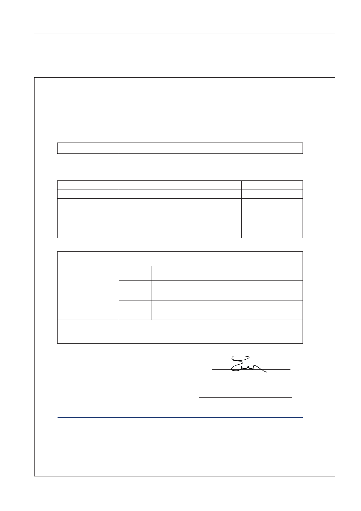
FCC Part 15 Subpart B Declaration of Conformity (DoC)
We, Intellian Technologies, Inc. located at 18-7, Jinwisandan-ro, Jinwi-myeon, Pyeongtaek-si, Gyeonggi-do 451-862,
Korea, declare that the product described below to which this declaration relates is in conformity with the
requirement of the FCC Part 15 Subpart B.
Product Information:
Product Name: Intellian v60Ka, 65cmKa-band Maritime Stabilized Antenna System
Test Result:
noitceseluRtseTdradnatS Test Report Number Result
FCC Part 15
Subpart B
AC power line conducted emission Section 15.107(a) ICES-003,
Section 6.1, Table 2 SKT-EFC-140043 Pass
Radiation emissionsbelow 1GHz Section 15.109(a) ICES-003,
Section 6.2, Table 5 SKT-EFC-140043 Pass
Radiation emissionsabove 1GHz Section 15.109(a) ICES-003,
Section 6.2.2, Table 7 SKT-EFC-140043 Pass
Supplementary Information:
Notified Body Involved:
(Testing Organization)
SK Tech Co., Ltd.
820-2, Wolmoon-ri, Wabu-up, Namyangju-si, Gyeonggi-do 482-905, Korea
Technical/Compliance
File Held by:
Intellian Technologies, Inc.
18-7, Jinwisandan-ro, Jinwi-myeon, Pyeongtaek-si, Gyeonggi-do 451-862, Korea
Place and Date of issue: Gyeonggi-do, Korea onSeptember 1, 2014
Authority: Kevin Eom/
Director,
Research and Development Signature:
Date: September 01, 2014
11
Doc Number IT14-DC1128-02
Intellian Technologies, Inc.
EMEA & APAC Headquarters
18-7, Jinwisandan-ro, Jinwi-myeon, Pyeongtaek-Si,
Gyeonggi-do 451-862, Korea
Tel: +82 2 511 2244
Intellian Technologies USA, Inc.
US Headquarters
9004 Research Drive
Irvine, CA 92618 USA
Tel: +1 949 727 4498
R&TTE Declaration of Conformity (DoC)
We, Intellian Technologies, Inc. located at 18-7, Jinwisandan-ro, Jinwi-myeon, Pyeongtaek-si, Gyeonggi-do 451-862,
Korea, declare that the product(s) described in the below to which this declaration relates is in conformity with the
essential requirements and other relevant requirements of the Radio and Telecommunications Terminal Equipment(R&TTE)
Directive (1999/5/EC).
Product Information:
Product Name(s): Intellian v60Ka, 65cm Ka -band Maritime Stabilized Antenna System
To provide the presumption of conformity in accordance to Annex III(encompassing Annex II) of Directive 1999/5/EC,
the following standards and normative documents are those to which the product’s conformance is declared,
and by specific reference to the essential requirements of Article 3 of the Directive 1999/5/EC.
1995/5/EC Article Standard(s) Applied in Full Test Report Number
SAFETY (Art 3.1.a) IEC EN 60950-1: 2006+A11:2009+A12010+A12:2011 SKTSCE-121011-044-A1
EMC (Art. 3.1.b)
IEC EN 60945: 2002
ETSI EN 301 489-1 V1.9.2: 2011-09
ETSI EN 301 489-17 V2.2.1: 2012-09
SKT-ECE-140074
SKT-ECE-140076
SPECTRUM (Art. 3.2)
ETSI EN 301 360 V1.2.1: 2006-02
ETSI EN 301 459 V1.4.1: 2007-06
ETSI EN 303 978 V1.1.2: 2013-02
2014 03254752 ETSI1
2014 03254752 ETSI3
2014 03254752 ETSI2
Supplementary Information:
Notified Body Involved:
SIEMC
775 Montague Expressway, Milpitas, CA 95035
Test Facility:
RF Part:
Nemko USA, Inc.
2210 Faraday Avenue, Suite 150 Carlsbad, CA 92008 USA
EMC Part
DT&C Co., Ltd.
42, Yurim-ro, 154beon-gil, Cheoin-gu, Yongin-si, Gyeonggi-do, Korea
449-935
Safety Part:
SK Tech Co., Ltd.
88, Geulgaeul-ro 81beon-gil, Wabu-eup, Namyangju-si, Gyeonggi-do
472-905, Korea
Technical/Compliance
File Held by:
Intellian Technologies, Inc.
18-7, Jinwisandan-ro, Jinwi-myeon, Pyeongtaek-si, Gyeonggi-do 451-862, Korea
Place and Date of issue: Gyeonggi-do, Korea on November 28, 2014
Authority: Kevin EOM/ Signature: ____________________________
Director,
Research and Development
Date: November 28, 2014

v60Ka– Marine Satellite Communication System
12
Intellian v60Ka Introduction
Intellian v60Ka (65cm) is a Ka-band maritime stabilized antenna, a ready-to-use system for Telenor on their Super-
fast Ka Band broadband Satellite service. The v60Ka offers robust Ka-band RF performance optimized for Telenor
Satellite Broadcasting's THOR 7 High Throughput Satellite (HTS) Ka-band service.
The v60Ka ACU includes Wi-Fi to allow wireless connection using the dedicated Intellian Aptus software for system
control and monitoring. The Aptus software automatically congures the antenna system, enabling true One Touch
Commissioning.
Equipped with Aptus®, the v60Ka antenna can be remotely accessed, monitored and controlled through serial
connection or secured TCP/IP network. Its graphic-based user interface provides easy-to-use operating environment.
The v60Ka also has an embedded web server and secured web user interface called Aptus Web for remote management
of the antenna on a web browser. Network connection can be easily setup through the front Management Ethernet
Port on the ACU that supports automatic IP conguration.
The antenna's 3-axis stabilized platform with advanced shock-resistance and vibration damping design of the
Pedestal is fully optimized to withstand the demanding maritime conditions which ensures reliable broadband
communications. The unlimited azimuth range ensures continuous tracking without unwrapping the cables in the
antenna and the low elevation angle (-20°) supports seamless signal reception at extremely high latitudes.
The v60Ka is built to meet or exceed the industry's most stringent standards such as FCC, ETSI, R&TTE. With its
frequency tuned radome and newly designed reector, the v60Ka offers the maximized performance on a Ka-band
service.
Introduction

13
Introduction
Intellian v60Ka Features
Ka-band optimized reector
The v60Ka carbon ber reector is designed and engineered to operate on the Ka-band while maximizing the RF performance.
The reector of the v60Ka is designed to be extremely precise and very stable in all operating conditions.
Frequency tuned radome
To ensure efcient operations for Ka-band systems, the signal loss of the radome itself is minimized and the performance
maximized with an optimized radome design that enhances the Ka-band system performance.
Gyro-free satellite search capability
Intellian’s new generation gyro-free satellite search function enables the v60Ka to acquire and lock onto the satellite without an
input from a ship's gyrocompass.
Graphical and user-friendly antenna control software
The v60Ka provides a newly developed, graphic-based antenna remote control program with an additional Software Development
Kit (SDK), allowing the NOC or service center to integrate antenna monitoring and control into its existing network management
systems in an easier, user-friendly, and convenient manner.
Dedicated Management Ethernet Port
The v60Ka has a Management Ethernet Port on the front of the ACU that enables direct and simple network connection between
a PC and the ACU. The Management Port allows Internet access and quick access to Intellian's remote management solution,
the Aptus Web.
Wireless access via Wi-Fi
The built-in Wi-Fi wireless network card enables the ACU to be wirelessly connected and can be turned on and off by a switch.
Wireless devices such as PCs, laptops and smartphones can be used to connect to the ACU and monitor, enabling users to
control and change the settings of Intellian antenna system wirelessly.
Industry-leading standards compliance
The v60Ka is designed to meet or exceed FCC and ETSI specications, as well as EN60945, EN60950, R&TTE, DNV2.4 Class C
specication.
Automatic satellite switching
The v60Ka supports auto satellite and beam switching for seamless continuous coverage.

v60Ka– Marine Satellite Communication System
14
System Conguration
For your satellite communication system to work properly, the system will have to be connected with all of the
provided components as shown in the gure below. A separate purchase of a satellite modem, ship’s gyrocompass,
and Intellian Dual VSAT Mediator may be required.
Basic system
configuration
AC 100 ~ 240VC
(50~60Hz, 4A)
AC 100 ~ 240VC
(50~60Hz, 1A)
Ship’s Gyrocompass (Not supplied)
NMEA
Modem Interface
PC Interface
BUC Interface
Modem Rx
Antenna Rx
Modem Tx
iDirect X7 Modem
(Not supplied)
Antenna Control Unit
1) Connect an RF cable from the antenna to Antenna RX port at the ACU.
2) Connect an RF cable from the antenna to Tx Out port at the modem.
3) Connect an RF cable from Modem Rx port at the ACU to Rx In port at the modem.
4) Connect a LAN cable from Ethernet port at the ACU to RJ45 connector 1 at the modem.
5) Connect the supplied BUC interface cable (Type: D-sub to RJ45) from BUC Interface (D-sub) port at the ACU to
BUC I/O (RJ45) port at the modem.
6) Connect a ship's gyrocompass to NMEA port at the ACU.
7) Supply ship's power to the system.

15
Installing Antenna
System Package
The packaged Intellian v60Ka includes the Antenna unit, lifting straps, ACU and an Installation kit box.
Antenna unit
ACU
Installation kit box
Installing Antenna

v60Ka– Marine Satellite Communication System
16
Antenna Unit
The antenna unit includes an antenna pedestal system inside of a radome. The Pedestal system consists of the
satellite antenna dish and RF components mounted on a stabilised pedestal assembly. The radome protects the
antenna pedestal assembly from the severe marine environment.
Antenna unit

17
Installing Antenna
ACU (Antenna Control Unit)
The digital VFD (Vacuum Fluorescent Display) allows for easy operation of the ACU, even in the dark.
The functions of the ACU are as follows :
• Setting the satellite
• Editing satellite information
• Setting the antenna parameter
• Setting the antenna manual search
• Setting the LNB local frequency
• Setting block zones
• Setting modem connections
• Setting GPS and Gyrocompass
• Display power status
• Built-in real-time diagnostics function
• Backup and restore the system settings
• Set up the interface with a PC
• Supports Wi-Fi ACU operation
• Recording antenna activities and rmware upgrade through USB
• Built-in web-based remote control management
• Front and rear panel Management Ethernet port
Antenna control unit
Rear panel
Front panel

v60Ka– Marine Satellite Communication System
18
Contains the items required for securing the antenna unit and ACU to the vessel.
Installation Kit
ACU box
Description Q'ty Size Remarks
Antenna Control Unit (ACU) 1 43.1 x 38 x 4.4cm
(17" x 15" x 1.7") Antenna Control Unit
RF Hazard Sticker 1 Radiation Safety Distance Label
Mounting Template 1
Wi-Fi Antenna 1 110mm
USB Flash Drive 1
Components box
Description Q'ty Size Remarks
ACU Bracket (Rack) 2 ACU-19inch Rack
ACU Bracket (Table) 2 ACU-Table
RG6 Cable 1 3m ACU to Modem
AC Power Cord (CEEE7/7) 1 1.5m ACU Power
AC Power Cord (USA) 1 1.8m ACU Power
4 Pin Power Connector 1 - CA 3 LD
PC Serial Cable 1 1.8m ACU to PC
USB Cable (A-A) 1 1.8m ACU to PC
Ethernet Cable (RJ45/LAN) 1 1.5m ACU to PC
iDirect Interface Cable 1 1.5m ACU to Modem
BUC Interface Cable(D-sub to RJ45) 1 1m ACU to Modem
D-sub 9 pin Male Connector 1 - ACU
N to F Adaptor 1 N(Male) to F(Female) Adaptor
Hex Bolt 5 M12 x 100L
Antenna-Deck 4 Sets :
Installation 1 Set : Spare
Flat Washer 5 M12
Spring Washer 5 M12
Hex Nut 10 M12
Hex Head Wrench Bolt 5 M6 x 40L
Radome (Spare Bolts)
Spring Washer and Flat Washer 5 M6
Self-Tapping Screw 5 M4 x 16 Table Mount Bracket
Flat Head Screw 10 M4 x 12L Rack Mount Bracket ACU
Sems Bolt 5 M3 x 12L Table Mount Bracket ACU

19
Installing Antenna
Planning the Installation
Selection of Antenna Installation Site
Install the antenna in accordance with the following procedures to insure maximum performance of the antenna.
The ideal antenna site has a clear view of the horizon or satellite all around. Please be sure there are no obstacles
within 15º above the center of the antenna. Any obstacles can prevent the antenna from transmitting and receiving
the satellite signal.
Do not install the antenna near the radar especially on the same plane, as its energy levels may overload the antenna
front-end circuits. It is recommended to position the antenna at least 4 feet (1.2 m) above or below the level of the
radar and a minimum of 15 feet (4.6 m) away from the high power short wave radars.
The mounting platform should be rigid enough and not subjected to excessive vibration. The movement of the
antenna can be minimized by installing on the vessels center line. If these conditions cannot be satised, select the
best site available minimizing the effects of obstructions, vibrations and position closest to the vessels center line.
Elevation limit of
obstacles
15°
Antenna Unit Obstacle
v60Ka– Marine Satellite Communication System
20
Congure Radiation Hazard/Block Zones
It is important to set up the radiation hazard or block zones for Intellian VSAT communication systems. The ACU can
be programmed with relative azimuth and elevation sectors to create up to ve zones where transmit power would
endanger personnel who are frequently in that area or blockage exists. Several things happen when the antenna is
within one of these zones.
1. “BLOCK” will be displayed on the ACU screen.
2. Tracking continues as long as the signal level is greater than the predened threshold value. When the signal level
drops below the threshold value the antenna will wait “Search Wait Time” parameter amount of time and re-target
the satellite you targeted last. The antenna will continue to re-target the satellite until the satellite is re-acquired
and tracking can be resumed.
3. A transmit inhibit output from the ACU will disable/mute the modem transmission.
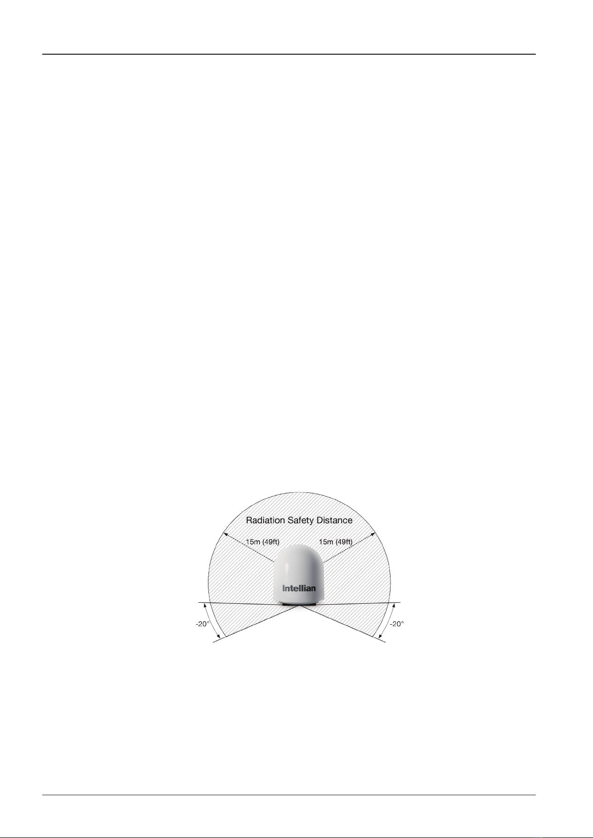
RF Hazard Precautions
The antenna is designed to be used with radiation transmit equipment manufactured by others. Exposure to RF
radiation, including exposure associated with an improper use of the transmit equipment, may be hazardous to
persons close to the above deck unit. Ensure safety of personnel who work on the system.
During transmission, ensure to keep the minimum safety distance. The recommended minimum safety distance to
the reector on the focal line is about 15m, based on a radiation level of 5mW/ cm2 that applies under occupational/
controlled environment. No hazard exists >20° below the antenna’s mounting plane.
Other manuals for V60KA
1
Table of contents
Other Intellian Satellite TV System manuals


