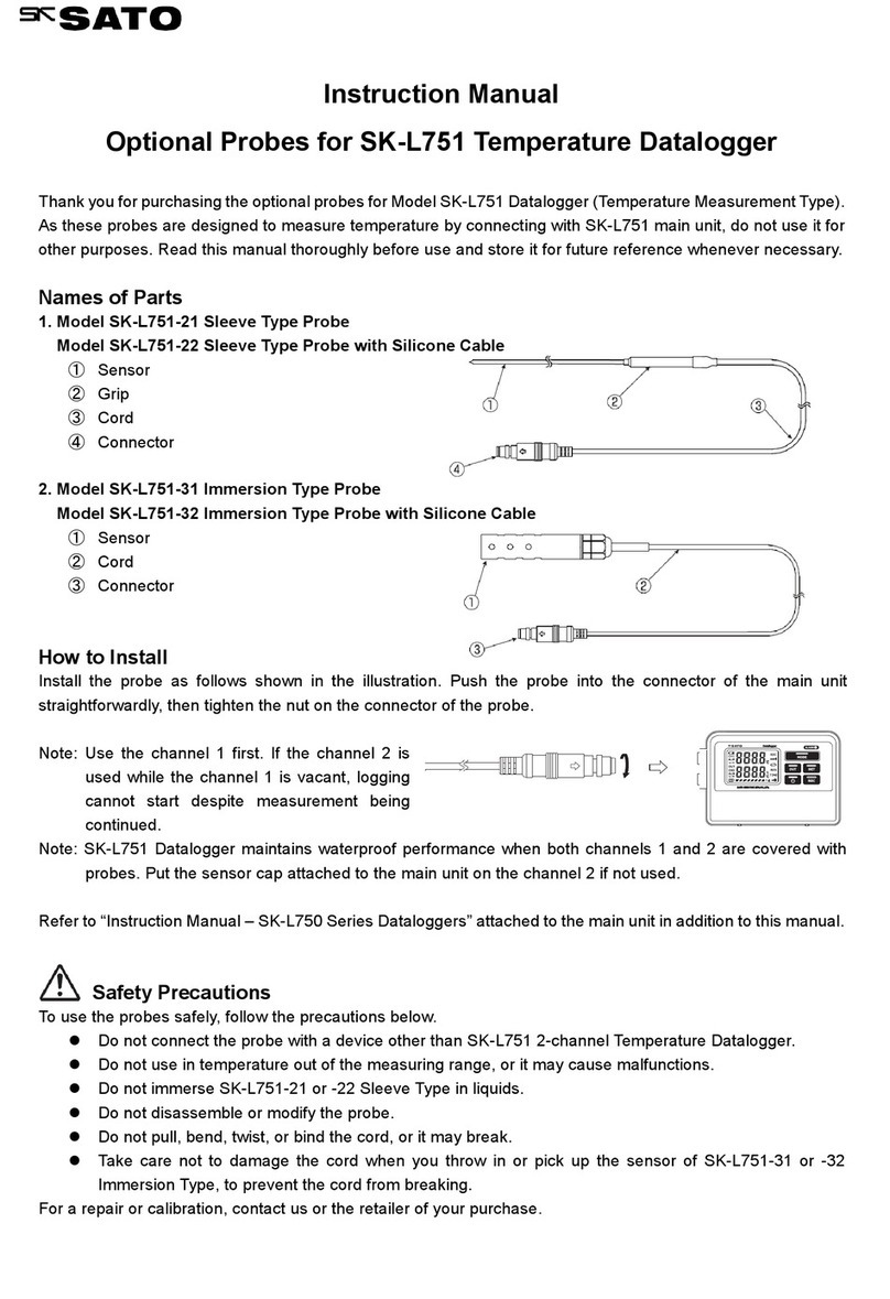
SATO Argox PI-1 30 Series User manual

User’s Manua
Data Collector
PI-XXXX, AP-XXXX,SP-XXXX,PE-XX
(X=0-9 , A-Z , a-z , dash , or blank)

i
Regulatory Compliance
FEDERAL COMMUNICATIONS COMMISSION INTERFERENCE
STATEMENT
This equipment has been tested and found to comply with the
limits for a Class B digital device, pursuant to part 15 of the FCC
Rules. These limits are designed to provide reasonable protection
against harmful interference in a residential installation. This
equipment generates, uses and can radiate radio frequency energy
and, if not installed and used in accordance with the instructions,
may cause harmful interference to radio communications.
However, there is no guarantee that interference will not occur in
a particular installation. If this equipment does cause harmful
interference to radio or television reception, which can be
determined by turning the equipment off and on, the user is
encouraged to try to correct the interference by one or more of
the following measures:
-Reorient or relocate the receiving antenna.
-Increase the separation between the equipment and receiver.
-Connect the equipment into an outlet on a circuit different from
that to which the receiver is connected.
-Consult the dealer or an experienced radio/ TV technician for
help.

ii
CAUTION:
Any changes or modifications not expressly approved by the
grantee of this device could void the user's authority to operate
the equipment.
RF exposure warning
The equipment complies with FCC RF exposure limits set forth for
an uncontrolled environment.
The equipment must not be co-located or operating in conjunction
with any other antenna or transmitter.
This device complies with Part 15 of the FCC Rules. Operation is
subject to the following two conditions:
(1) this device may not cause harmful interference, and
(2) this device must accept any interference received, including
interference that may cause undesired operation.

iii
To ensure that RF exposure levels remain at or below the tested
levels, use a belt clips, holsters or similar accessories that have no
metallic component in the assembly and must provide a minimum
separation distance of 5mm between the device and the body.
The FCC has granted an Equipment Authorization for this device
with all reported SAR levels evaluated as in compliance with the
FCC RF exposure guidelines. SAR information on this device is on
file with the FCC and can be found under the Display Grant section
of www.fcc.gov/eot/ea/fccid after searching on FCCID:NBF-PI-1X30
RF Exposure Information (SAR)
This device meets the government’s requirements for exposure to
radio waves. This device is designed and manufactured not to
exceed the emission limits for exposure to radio frequency (RF)
energy set by the Federal Communications Commission of the U.S.
Government.
The exposure standard employs a unit of measurement known as
the Specific Absorption Rate, or SAR. The SAR limit set by the FCC is
1.6 W/kg. Tests for SAR are conducted using standard operating
positions accepted by the FCC with the EUT transmitting at the
specified power level in different channels.

iv
CAUTION: EXPLOSION HAZARD
Do not disassemble, short circuit, heat the battery or dispose of in
fire. Store battery pack in a proper place. Do not expose to
temperature above 60℃/140℉. Use specified charger only. Please
dispose of the used batteries following the rules or laws issued by
the local government.
警告:電池若未妥善處理,可能會導致爆炸。
請勿拆卸電池,或用火銷毀電池。請將電池放置於兒童拿不到的地方。
請使用專用充電器充電,並請依照當地政府或法律規定妥善處理廢棄
電池。
經型式認證合格之低功率射頻電機, 非經許可,公司, 商號或使用者
均不得擅自變更頻率,加大功率或變更原設計之特性及功能
低功率射頻電機之使用不得影響飛航影響安全及干擾合法通信, 經發
現有干擾現象時,應立即停用,並改善至無干擾時方得繼續
使用前項合法通信,指一電信法規定作業之無線電通信低功率射頻電
機需忍受合法通信或工業,科學及醫療用電波輻射性電機設備之干擾

i
Release Note
Version
Date
Note
V1.0
02/22 2017
Initial release

ii
Content
1 Introduction.......................................................................... 1
1.1 Unpacking ................................................................. 2
1.2 Understand your terminal ........................................ 4
1.2.1 Terminal ........................................................ 4
1.2.2 Holder(Option).............................................. 5
1.3 Indicators .................................................................. 6
1.3.1 LED ................................................................ 6
1.3.2 Buzzer............................................................ 8
1.3.3 Vibration ....................................................... 8
1.4 Keypad ...................................................................... 9
1.5 Power source .......................................................... 14
1.5.1 Inserting or replacing battery ..................... 15
1.5.2 Charge the battery...................................... 18
2 Get started.......................................................................... 20
2.1 Set up your terminal............................................... 20
2.2 User interface ......................................................... 21
2.3 Connection ............................................................. 23
2.3.1Remote link connection.......................................... 24
2.4 Attach the hand strap ............................................. 27
3 Controls and settings.......................................................... 29
3.1 User Menu .............................................................. 29
3.1.1 Run Program ............................................... 30
3.1.2 Remote Link ................................................ 30
3.1.3 Scanner(HID)............................................... 31

iii
3.1.4 Information ................................................. 32
3.2 System Menu .......................................................... 33
3.2.1 Remote Link ................................................ 33
3.2.2 Disk info ...................................................... 33
3.2.3 Timer setting............................................... 34
3.2.4 Environment ............................................... 35
3.2.5 Test.............................................................. 36
3.2.6 System info.................................................. 38
3.3 Supervisor Menu .................................................... 39
3.3.1 Remote Link ................................................ 40
3.3.2 Format disk ................................................. 43
3.3.3 Setting......................................................... 44
3.3.4 Information ................................................. 49
4 Applications ........................................................................ 50
5 Troubleshooting.................................................................. 51
5.1 Hardware issues...................................................... 51
5.2 Communication issues............................................ 52
5.3 Barcode scanning issues ......................................... 53
6 Specifications...................................................................... 54
Appendix A .............................................................................. 58

1
1Introduction
PI series is a lightweight, portable data terminal (PDT)
for data capture and collection. This manual will help
you to get to know PI series and utilize it well.
Features
■Scratch-resistant keypad Coated with PC
(polycarbonate), the letters and numbers on the keys
won’t wear off between uses.
■Battery cover open detection When the switch of
the battery cover is up, the system automatically
saves your files and shut down.
■Large flash memory PI series offers more flash
memory than the rivals on the same level. The
standard is 20 MB, and the optional is 60 MB.
■Wi-Fi connectivity You can exchange data over a
Wi-Fi network.(PI-1030)
■Backup battery The backup battery gives you
additional 15 minutes to finish your job if the primary
batteries wear out.

2
1.1 Unpacking
Make sure all of the following items are included in your
package.
PI series
Quick Start Guide
USB Cable
or
RS-232 Cable with USB
power cord
Holder(Option)
Hand Strap

3
Plug and Power Supply (Option)
When you receive your terminal, open the package
immediately and inspect for shipping damage. If you
discover any damage, contact the shipping company and
file a claim. Argox is not responsible for any damage
incurred during shipping. Save all package materials for
the shipping company to inspect.
Note If any item is missing, please contact your
local dealer.

4
1.2 Understand your terminal
1.2.1 Terminal
Left
Front
Right
Back
Top
Bottom
1
LED
Three LEDs.
2
LCD Display
A mono LCD.
3
Keypad
A 25-key keypad.
4
Battery Cover
The battery cover.
5
Battery Cover Switch
Open and close the battery cover.
6
Reading Window
The bar code reading beam is emitted
through this window.
7
Speaker
Buzzer sound
1
2
3
6
8
5
4
7

5
8
Connector
A port to connect computer
1.2.2 Holder(Option)
The holder is used to hold your terminal in its standing
position.
In the bottom of holder, make sure cable wire is
installed as below.

6
1.3 Indicators
PI series has three LEDs and a buzzer to indicate its current
status.
1.3.1 LED
Your terminal has three LEDs on the upper-left corner.
They have different behavior. The table below gives
information about the status they indicate.
LED
Color
Scan LED
Green, Red and Orange
BT or Wi-Fi LED
Blue
BT or Wi-Fi LED
Charger LED
Scan LED

7
Charger LED
Red
LED
Behavior
Status
Note
Scan
LED
Solid green
User defined
Use SDK.
Solid red
User defined.
Use SDK.
Solid orange
User defined.
Use SDK.
Flashing
green
Transmitting data or
user defined.
Use SDK.
Flashing red
User defined.
Use SDK.
Flashing
orange
User defined.
Use SDK.
Off
No data transmission
or user defined.
Use SDK.
BT &
Wi-Fi
LED
Solid blue
Your terminal is
connected through
Bluetooth or Wi-Fi.
Flashing
blue
Your terminal is ready
to be connected
through Bluetooth or
Wi-Fi.
Off
Bluetooth or Wi-Fi is
turned off.
Default
Charger
LED
Solid red
Your terminal is fully
charged or connected
to a power source.
Controlled
by
hardware.
Flashing red
Charging.
Controlled

8
LED
Behavior
Status
Note
by
hardware.
Off
Your terminal is not
connected to any
power source.
Controlled
by
hardware.
1.3.2 Buzzer
You can define the status the vibration indicates using
the SDK.
Sound
Status
1 Short Beep
A key is pressed.
A good scan.
An error occurred.
2 Short Beep
The battery is low.
4 Short Beep
Battery is too low to turn off
terminal.
1.3.3 Vibration
You can define the status the vibration indicates using
the SDK.
Vibration
Status
Vibrate
A good scan.

9
1.4 Keypad
Scan key
Cursor keys
Control keys
Numeric keys
User-defined keys
Power key
Scan key
Scan a bar code.
Cursor keys
Up
Move the highlight bar up.
Fn+Up
Open Message Menu.
Down
Move the highlight bar down.
Fn+Down
Adjust the backlight brightness. The
brightness repeats the sequence
0123.
Left
Move the highlight bar to the top.
Fn+Left
Reduce the volume.
Right
Move the highlight bar to the bottom

10
Cursor keys
Fn+Right
Increase the volume.
Control keys
ESC
The Escape
key.
1. Go up one level in a menu.
2. Give up changing a setting.
3. Exit a program.
Fn
The Function
key.
Use with other keys. Ex:
“Fn+Down Arrow”is to adjust
the backlight brightness. The
function of F0 - F9 (Fn+0 - 9)
can be defined using an SDK.
ENT
The Enter key.
1. Enter a menu.
2. Select an option.
BS
The Backspace
key.
1. Delete a character to the
left of the cursor.
Numeric keys
You can use the keypad to enter numbers or English
characters, depending on the mode you’re using.
1
1. Enter the number one.
2. Enter these signs: plus (+), minus (-), star
(*) and slash (/).
2
1. Enter the number two.
2. Enter the letters A, B, C.

11
Numeric keys
3
1. Enter the number three.
2. Enter the letters D, E, F.
4
1. Enter the number four.
2. Enter the letters G, H, I.
5
1. Enter the number five.
2. Enter the letters J, K, L.
6
1. Enter the number six.
2. Enter the letters M, N, O.
7
1. Enter the number seven.
2. Enter the letters P, Q, R, S.
8
1. Enter the number eight.
2. Enter the letters T, U, V.
9
1. Enter the number nine.
2. Enter the letters W, X, Y, Z.
0
1. Enter the number zero.
2. Enter these characters: space ( ), at (@),
comma (,) and semicolon (;).
Alpha
Switch the input method between numbers,
uppercase and lowercase characters.
.
1. Enter a period (.).
2. Enter these symbols: dollar sign ($),
percent sign (%), ampersand (&) and
number sign (#).

12
User-defined keys
P1
User-defined key.
P2
User-defined key.
P3
User-defined key.
Power key
Turn on or turn off your terminal.
Power combination key
You can use the key combinations to enter different
menus or modes. Press and hold the combination of
keys, until your terminal responds.
3 + 9 + Power
System Menu.
1 + 3 + 0 + Power
Supervisor Menu.
1 + 3 + Power
Force mode.
P1 + P2 + P3 + Power
BIOS reset.
SCAN + Power
Warm reset.
SCAN + Power (5 sec)
Cold reset. You need to press
the keys for 5 seconds.
This manual suits for next models
4
Table of contents
Other SATO Data Logger manuals
Popular Data Logger manuals by other brands
Fidelis
Fidelis Network Series quick start guide
Datafox
Datafox PZE-MasterIV manual
CSI
CSI CSCU-ST-WF01 Quick installation guide
Extech Instruments
Extech Instruments CO210 user manual
Eagle Tree Systems
Eagle Tree Systems Dual A/D Expander V2 instruction manual
Campbell
Campbell CR300 series Operator's manual
Measurement Computing
Measurement Computing USB-5201 user guide
MadgeTech
MadgeTech SciTemp140-PT Product user guide

Telit Wireless Solutions
Telit Wireless Solutions SL869-T user guide
bmcm
bmcm USB-AD12f quick start guide
IOtech
IOtech DaqBook/3000USB user manual
Lutron Electronics
Lutron Electronics BTM-4208SD Operation manual
