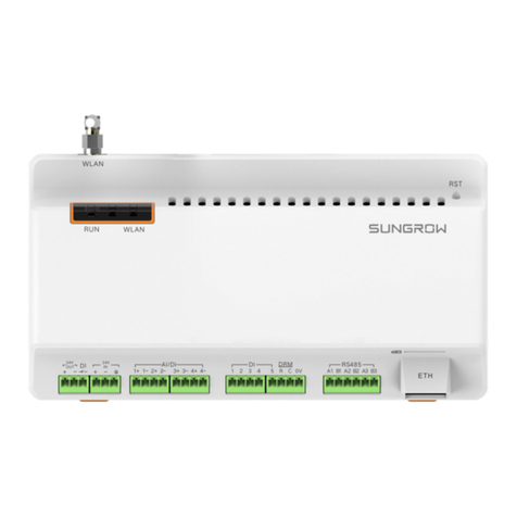
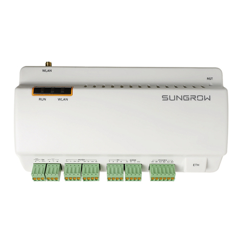
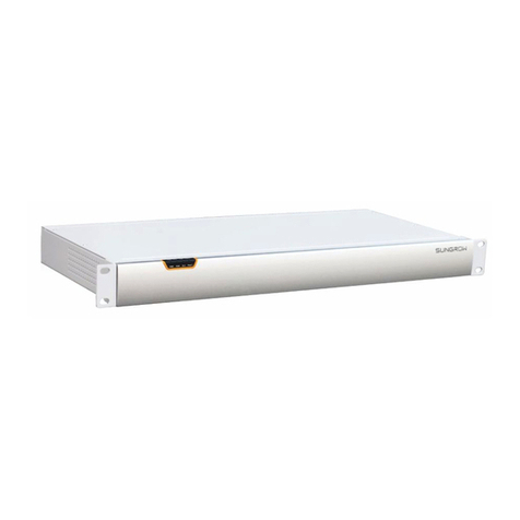
Sungrow Logger1000 User manual

Logger1000-UEN-Ver11-201903
Logger1000
Data Logger
User Manual


I
Content
1About this Manual ...................................................................1
1.1 Intended Use........................................................................................................1
1.2 Target Group ........................................................................................................1
1.3 How to Use This Manual ...................................................................................1
1.4 Symbol Explanations.........................................................................................2
1.5 Warning .................................................................................................................2
2Safety Instruction ....................................................................6
3Product Introduction ...............................................................8
3.1 Function Description.........................................................................................8
3.1.1 Brief Product Introduction..................................................................................8
3.1.2 Networking Application ...................................................................................... 9
3.2 Appearance ........................................................................................................11
3.3 Dimensions........................................................................................................ 12
4Installation Flow.....................................................................13
5Mechanical Installation .........................................................14
5.1 Unpacking and Inspection ........................................................................... 14
5.2 Installation Location Requirements........................................................... 15
5.3 Installation Tools .............................................................................................. 16
5.4 Installing Logger1000 .................................................................................... 16
5.4.1 Wall-Mounting......................................................................................................17
5.4.2 Guide Rail-Mounting ..........................................................................................18
5.5 Installing Antenna ........................................................................................... 19
5.6 Installing Power Box ....................................................................................... 20
6Electrical Connection.............................................................21
6.1 Safety Instructions........................................................................................... 21
6.2 Port Introduction............................................................................................. 21
6.3 Connection to PV Devices............................................................................. 22

II
6.3.1 Connection to Inverter ......................................................................................22
6.3.2 Connection to Energy Meter ...........................................................................26
6.3.3 Connection to Meteo Station..........................................................................26
6.4 Connection to Background...........................................................................27
6.5 Connection to Power Supply........................................................................28
6.6 Cable Routing Requirements .......................................................................30
7Commissioning ......................................................................31
7.1 Inspection before Commissioning .............................................................31
7.2 Commissioning Steps..................................................................................... 31
8Web Interface .........................................................................33
8.1 Running Requirements ..................................................................................33
8.2 Preparation before Ethernet Login.............................................................33
8.3 Login Steps ........................................................................................................ 33
8.3.1 Ethernet Login......................................................................................................33
8.3.2 WiFi Login...............................................................................................................34
8.4 Web Main Interface .........................................................................................35
8.5 Web Menu.......................................................................................................... 36
8.6 Operation Procedure ......................................................................................36
8.7 Overview............................................................................................................. 37
8.7.1 General Information ...........................................................................................37
8.7.2 Current Alarms......................................................................................................38
8.8 Device Monitoring........................................................................................... 38
8.8.1 Real-Time Information .......................................................................................38
8.8.2 DC Data...................................................................................................................39
8.8.3 Initial Parameter...................................................................................................39
8.8.4 Protection Parameter.........................................................................................40
8.8.5 General Parameter ..............................................................................................40
8.8.6 Device Instruction...............................................................................................41
8.8.7 Device Information.............................................................................................41
8.9 Device Maintenance ....................................................................................... 42
8.9.1 Device List..............................................................................................................42

III
8.9.2 Firmware Update.................................................................................................44
8.9.3 Inverter Log...........................................................................................................44
8.10 History Data....................................................................................................... 44
8.11 System................................................................................................................. 45
8.11.1 Running Information .......................................................................................45
8.11.2 System Maintenance........................................................................................45
8.11.3 Remote Maintenance.......................................................................................47
8.11.4 Message Export .................................................................................................47
8.11.5 System Time........................................................................................................48
8.11.6 Forwarding Configuration..............................................................................49
8.11.7 Interface ...............................................................................................................53
8.12 About................................................................................................................... 55
9Grid Dispatching Function ....................................................56
9.1 Function Description...................................................................................... 56
9.2 Interface Description...................................................................................... 57
9.2.1 Digital Control Interface....................................................................................57
9.2.2 Analog Control Interface...................................................................................59
9.2.3 DRM Control Interface .......................................................................................59
9.3 Power Control ................................................................................................... 60
9.3.1 Active Power..........................................................................................................60
9.3.2 Reactive Power.....................................................................................................63
9.3.3 Emergency Button ..............................................................................................66
10 Device Maintenance ..............................................................67
10.1 Safety Instructions........................................................................................... 67
10.1.1 Safety Rules.........................................................................................................67
10.1.2 Five Safety Rules................................................................................................67
10.2 Maintenance ..................................................................................................... 68
10.3 Troubleshooting .............................................................................................. 68
11 Appendix ................................................................................70
11.1 Technical Data .................................................................................................. 70
11.2 Quality Guarantee ........................................................................................... 70

1
1 About this Manual
This manual is valid for the following data loggers researched and manufactured by
Sungrow Power Supply Co., Ltd.
Logger1000
1.1 Intended Use
This manual is intended to provide users with detailed information on the
Logger1000 as well as installation, operation, and maintenance description.
1.2 Target Group
This manual is applicable to technical personnel who are responsible for the
installation, operation and maintenance of the Logger1000 and to users who need
to perform daily operation. Readers should have some electrical knowledge and be
familiar with electrical principles and electrical components. This manual does not
cover the electrical connections of the inverter and the Meteo Station or related
safety instructions. For the details of the electrical connections of these devices,
refer to the corresponding manuals.
1.3 How to Use This Manual
Read this manual carefully before performing operation on the device. This manual
must be stored at hand and available at all times.
All rights reserved including the pictures, symbols, and markings used in this
manual. Any reproduction or disclosure, even partially, of the contents of this
manual is strictly prohibited without prior written authorization of SUMGROW. The
content of the manual will be periodically updated or revised as per the product
development. It is probably that there are changes in manuals for the subsequent
module edition. If there any mismatch between the product and its manual, the
actual product shall prevail and the manual of the latest version can be obtained
from SUMGROW.

1 About this Manual User Manual
2
1.4 Symbol Explanations
This manual contains important safety and operational instructions that must be
accurately understood and respected during the installation and maintenance of
the equipment.
To ensure the optimum use of this manual, note the following explanations of the
symbols used.
DANGER indicates a hazard with a high level of risk which, if not avoided,
will result in death or serious injury.
WARNING indicates a hazard with a medium level of risk which, if not
avoided, could result in death or serious injury.
CAUTION indicates a hazard with a low level of risk which, if not avoided,
could result in minor or moderate injury.
NOTICE indicates a situation which, if not avo
ided, could result in
equipment or property damage.
NOTE indicates additional information, emphasized contents or tips to help
you solve problems or save time.
1.5 Warning
This device complies with Part 15 of the FCC Rules. Operation is subject to the
following two conditions:
(1) This device may not cause harmful interference, and

User Manual 1 About this Manual
3
(2) This device must accept any interference received, including interference that
may cause undesired operation.
Note: This product has been tested and found to comply with the limits for a Class B
digital device, pursuant to Part 15 of the FCC Rules. These limits are designed to
provide reasonable protection against harmful interference in a residential
installation. This product generates, uses, and can radiate radio frequency energy
and, if not installed and used in accordance with the instructions, may cause
harmful interference to radio communications. However, there is no guarantee that
interference will not occur in a particular installation. If this product does cause
harmful interference to radio or television reception, which can be determined by
turning the equipment off and on, the user is encouraged to try to correct the
interference by one or more of the following measures:
—Reorient or relocate the receiving antenna.
—Increase the separation between the equipment and receiver.
—Connect the equipment into an outlet on a circuit different from that to which the
receiver is connected.
—Consult the dealer or an experienced radio/TV technician for help.
Please take attention that changes or modification not expressly approved by the
party responsible for compliance could void the user’s authority to operate the
equipment.
This equipment complies with FCC/IC RSS-102 radiation exposure limits set forth for
an uncontrolled environment. This equipment should be installed and operated
with minimum distance 20cm between the radiator & your body.
This device complies with Industry Canada licence-exempt RSS standard(s).
Operation is subject to the following two conditions:
(1) this device may not cause interference, and
(2) this device must accept any interference, including interference that may cause
undesired operation of the device.
Le présent appareil est conforme aux CNR d'Industrie Canada applicables aux
appareils radioexempts de licence. L'exploitation est autorisée aux deux conditions
suivantes :
(1) l'appareil ne doit pas produire de brouillage, et
(2) l'utilisateur de l'appareil doit accepter tout brouillage radioélectrique subi, même
si le brouillage est susceptible d'en compromettre le fonctionnement.
Under Industry Canada regulations, this radio transmitter may only operate using an

1 About this Manual User Manual
4
antenna of a type and maximum (or lesser) gain approved for the transmitter by
Industry Canada. To reduce potential radio interference to other users, the antenna
type and its gain should be so chosen that the equivalent isotropically radiated
power (e.i.r.p.) is not more than that necessary for successful communication.
Conformément à la réglementation d'Industrie Canada, le présent émetteur radio
peut
fonctionner avec une antenne d'un type et d'un gain maximal (ou inférieur)
approuvé pour l'émetteur par Industrie Canada. Dans le but de réduire les risques de
brouillage radioélectrique à l'intention des autres utilisateurs, il faut choisir le type
d'antenne et son gain de sorte que la puissance isotrope rayonnée équivalente
(p.i.r.e.) ne dépasse pas l'intensité nécessaire à l'établissement d'une communication
satisfaisante.
This equipment complies with FCC/IC RSS-102 radiation exposure limits set forth for
an uncontrolled environment. This equipment should be installed and operated
with minimum distance 20cm between the radiator & your body.
ce matériel est conforme aux limites de dose d'exposition aux rayonnements, FCC /
CNR-102 énoncée dans un autre environnement.cette eqipment devrait être installé
et exploité avec distance minimale de 20 entre le radiateur et votre corps.
The user manual for local area network devices shall contain instructions related to
the restrictions mentioned in the above sections, namely that:
(i) the device for operation in the band 5150-5250 MHz is only for indoor use to
reduce the potential for harmful interference to co-channel mobile satellite systems;
(ii) the maximum antenna gain permitted for devices in the bands 5250-5350 MHz
and 5470-5725 MHz shall comply with the e.i.r.p. limit; and
(iii) the maximum antenna gain permitted for devices in the band 5725-5825 MHz
shall comply with the e.i.r.p. limits specified for point-to-point and non
point-to-point operation as appropriate.
(i)Les dispositifs fonctionnant dans la bande 5150-5250 MHz sont réservés
uniquement pour une utilisation à l'intérieur afin de réduire les risques de brouillage
préjudiciable aux systèmes de satellites mobiles utilisant les mêmes canaux.
(ii) le gain d'antenne maximal autorisé pour les appareils dans les bandes 5250-5350
MHz et 5470-5725 MHz doivent respecter le pire limiter; et
(iii) le gain d'antenne maximal autorisé pour les appareils dans la bande 5725-5825
MHz doivent respecter le pire limites spécifiées pour le point-à-point et
l'exploitation non point à point, le cas échéant.
Users should also be advised that high-power radars are allocated as primary users
(i.e. priority users) of the bands 5250-5350 MHz and 5650-5850 MHz and that these
radars could cause interference and/or damage to LE-LAN devices.
6
2 Safety Instruction
This chapter mainly introduces safety instructions that need to be respected during
the operation of Logger1000.
The Logger1000 has been designed and tested strictly according to international
safety regulations. As electrical and electronic equipment, the Logger1000 must be
installed, commissioned, operated, and maintained in strict accordance with related
safety instructions. Incorrect operation or misuse of the device may cause:
damage to personnel safety of the operators or the third party
damage to the Logger1000 or other properties belong to the operators or the
third party
Therefore, the following safety instructions must be read and always kept in mind
prior to any work. All detailed work-related safety warnings and notes will be
specified at the critical points in corresponding chapter.
All operation and electrical work must only be performed by qualified
personnel.
Before Installation
After receiving the device, please check if there is damage caused during
transport. Contact SUMGROW
or the forwarding company once any
problem is detected.
The related operators must be familiar with the safety instructions in this
manual and other safety regulations about the installation, operation and
maintenance of the Logger1000.
Move, transport, install, operate, and maintain the Logger1000 correctly
and appropriately.

User Manual 2 Safety Instruction
7
During Installation
The Logger1000 can only be used as described in this manual. Altering the
product without authorization or using
spare parts not sold or
recommended by SUMGROW may lead to fire, electric shock or other
damages.
Disconnect all electrical connections and the upstream input switch and
make sure the Logger1000 is voltage-free during installation.
Maintenance and Replacement
The maintenance of the Logger1000 can only be performed by qualified
personnel from service dept. of SUMGROW or other qualified personnel.
User can never maintain or replace the modules and other parts. Serious
personal injury or property loss may follow if otherwise.
Never replace the internal components of the Logger1
000 without
authorization. SUMGROW shall not be held liable for any possible damage
caused by ignorance of this warning.

8
3 Product Introduction
3.1 Function Description
3.1.1 Brief Product Introduction
The Logger1000 is a device used for data collection, power control, and protocol
conversion for inverters and other PV equipment in the PV plant. The device is also
integrated with communication gateway and plant O&M function.
The Logger1000 is featured as flexible networking, auxiliary maintenance, and easy
operation.
Flexible networking
Support of RS485, Ethernet, and Wi-Fi communication
Support of access by various environment sensors, energy meters, Meteo
Stations, inverters, and other equipment
Auxiliary maintenance
Support of batch inverter parameter setting and software upgrading
Support of remote desktop function, lower maintenance costs
Support of grid control instruction and power factor control
Support of local real-time monitoring, unnecessary to connect the Internet
Easy operation
Auto search and allocation of inverter address
Embedded web operation interface, support of mobile phone access, free
download of the App

3 Product Introduction User Manual
10
The Logger1000 supports various communication manners such as Wi-Fi.
The Logger1000 is connected to various environment sensors, energy meters,
Meteo Stations, and inverters in the PV power generation system via an RS485
bus.
Users can access the Web interface via mobile phone or PC, on which parameter
configuration and remote on-line upgrading can be performed.
The Logger1000 can transmit data to iSolarCloud and forward background
instructions to downstream devices.
The Logger1000 is equipped with grid dispatching function, including active
power control, reactive power regulation, etc.

User Manual 3 Product Introduction
11
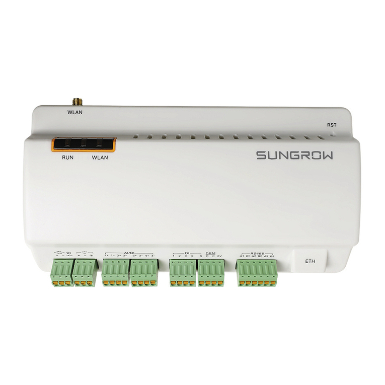
3.2 Appearance
Views of the Logger1000 are shown in the following figure.
Front view
Rear view
Bottom view
Side view
A
B
C
D
Fig. 3-1 Appearance
Item
Designation
Description
A
Indicator
Indicate the running state of the Logger1000
B
Vent
-
C
WLAN antenna mounting
hole
-
D
Wiring terminal
Refer to "Tab. 6-1 Port description"
Indicator
Indicator
(print)
LED color LED status Description
Running
indicator (RUN) Red/green
Off
No external power supply
connected
Slow flash
(Green) Normal running
Slow flash
(Red)
Device alarm
Steady on
(Red)
Logger1000 running fault
WLAN indicator
(WLAN) Blue
Off
No data communication
Steady on
Wi-Fi connected successfully
Slow flash
Data communication in process
Slow flash means that the indicator flashes once every second.

3 Product Introduction User Manual
12
Slow flash of the communication indicator indicates data communication in process. If
there has been no data communication with iSolarCloud for 10s, the indicator will
keep steady on.
3.3 Dimensions
Width (W)
Height
(H)
Depth (D)
Fig. 3-2 Dimensions
Width (W)
Height (H)
Depth (D)
200mm
110mm
60mm

13
4 Installation Flow
The following figure shows the overall installation flow of Logger1000.
Mechanical installation
Electrical installation
Check before commissioning
Running steps
Start
Ends
1
2
Unpacking and Inspection
4
3
5
6
Installation location selection
Fig. 4-1 Installation flow
Tab. 4-1 Description of the installation flow
No.
Procedure
Reference chapter
1
Unpacking and inspection
5.1
2
Installation location selection
5.2
3
Mechanical installation
5.4~5.6
4
Electrical installation
6
5
Check before commissioning
7.1
6
Running steps
7.2

14
5 Mechanical Installation
5.1 Unpacking and Inspection
Check the scope of delivery for completeness according to the packing list. The
following items should be included.
ABD
G
CE
FHIJ
Fig. 5-1 Scope of delivery
Item
Designation
Description
A
Logger1000
Logger1000
B Documents
Quick User Manual, quality certificate, packing list, product
test report, and warranty card
C
Communicatio
n terminal
resistor
6x120Ω (Note: if there are more than 15 devices
connected on the RS485 bus, it is recommended to
connect a 120Ω terminal resistor in parallel on the A and B
lines at the head or tail end of the bus)
D
Nylon cable
tie
Used to tie cables
E
Fastener
assembly
4 sets, M4X16, used for wall-mounting to fasten the device
on the metal surface
F
Expansion
bolt
4 sets, ST4.8X19, used for wall-mounting to fasten the
device on the concrete wall
G
Terminal
fastener
2 sets, E/UK-1201442, fixed on the guide rail to prevent
the Logger1000 from moving
H
Guide rail
Length: 240mm
I
WLAN
antenna
-
J Power box
Converters the AC current into DC current
Length of supporting guide rail: 170mm
Table of contents
Other Sungrow Data Logger manuals

Sungrow
Sungrow Logger1000A User manual

Sungrow
Sungrow Logger4000 User manual

Sungrow
Sungrow Logger1000A User manual

Sungrow
Sungrow Logger 3000 User manual

Sungrow
Sungrow 1000A User manual

Sungrow
Sungrow Logger3000 User manual

Sungrow
Sungrow Logger1000A User manual

Sungrow
Sungrow Logger1000B User manual

Sungrow
Sungrow Logger3000 User manual