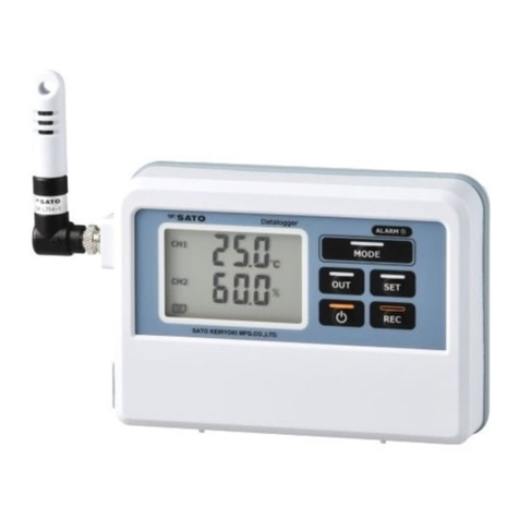
SATO SK-L400T User manual

Instruction Manual
No. 8191-00 4-ch Datalogger
Model SK-L400T
(Temperature measurement type)
3-4, Kanda-kajicho, Chiyoda-ku, Tokyo 101-0045 Japan
URL: http://www.sksato.co.jp/english/
Q.11

1
Thank you for purchasing the temperature measurement type 4-ch Datalogger Model SK-L400T
-This product is designed to measure temperature connecting k type thermocouple probe. Do not use it for
other purposes.
-Read this manual thoroughly before using the digital thermometers and keep the manual in a safe place
for future reference whenever necessary.
Warning
The SK-L400T is not explosion-proof. Never use it in an atmosphere containing flammable gases.
Beware of explosion!
There is a risk of explosion. Take extreme care.
Warnings on Usage
For your safety and proper use of the SK-L400T, be sure to observe the following:
- Never disassemble or modify the unit. Doing so may cause a malfunction.
- The unit is precision-machined. Never drop the unit or knock it over.
- Do not use the unit in a place exposed to direct sunlight or near a heat source. Doing so affects the
measurement accuracy, and could result in a deformation or malfunction of the unit.
- If this unit is used in an environment where electrical noise is generated, the display may become unstable
or the measurement error may increase.
- The main unit and sensor are not waterproof. Never let them get wet.
- Measuring temperatures outside the measurable range may result in unit and/or sensor malfunctions.
- If the unit is not to be used for a long period of time, remove the batteries. Otherwise, the batteries may
leak, resulting in malfunctions.
- Do not dispose of used batteries in a fire.
- Keep the battery out of the reach of children. If the battery has been swallowed accidentally, consult a
doctor immediately.
- For environmental conservation purposes, dispose of the used battery in compliance with local rules and
regulations.
- Do not wash or wipe this unit with alcohol, thinner, or other organic solvents. If the unit becomes dirty, wipe
it with a tightly-wrung gauze or the like that has been dipped in warm water with neutral detergent.
For repair or calibration, contact us or the retailer from which the Datalogger was purchased.
Windows is trademark of Microsoft Corporation in the USA and the other countries.
All other products and company names mentioned in this manual are trademark of their respective owners.

2
Overview
This temperature datalogger uses K-type thermocouple sensor. Four probes can be connected at the same
time, and four channels can be displayed on the large LCD.
An SD card is used as the recording medium.
Features
●Measure the temperatures of four locations at same time.
Up to four K-type thermocouple probes can be connected. Simultaneously displays four temperatures from
four locations (channels) on the large LCD for easy reading. By using the ASTM (former ANSI) miniature
connector for the K-type thermocouple, various optional sensors can be connected.
●Logging the measured values on the SD card
The measured values can be logged on the SD card installed in the unit.
By using the analysis software "4ch DATALOGGER for Windows" included with the unit, graph plotting
and data analysis can be easily done.
●Manual logging, preset logging, memo function
Equipped with manual logging, preset logging that enables you to set the time at which to start or stop
logging, and a memo function for quickly logging the current measured value. Can be used for various
data collection operations.
●Alarm issuance at upper and lower limit temperatures
Different alarm values (upper and lower) can be set for the four channels. If the measured value goes out
of the set limit value, a buzzer sounds and the LED lamp flashes to alert.
●Display of various calculation results
Display of the maximum (MAX) or minimum (MIN) value, relative value (REL function), temperature
difference (T1 – T2 function), offset function.
●Backlight function: The backlight makes it easy to read in dark places.
●Mounting on a tripod
The threaded hole on the back of the unit makes it easy to mount the unit on a tripod.
Before use
Check whether the unit was damaged during shipping.
If it is damaged, contact us or the store where you purchased the unit.

3
Names of components
●Main unit
①LCD: Displays the temperature reading and
state of the unit.
②LED lamp :
Flashes while the alarm is sounding.
③Power/Backlight key :
Turns the power on or off. Also used to turn
on the backlight.
④REL/SET/ESC key :
Activates the REL function. Also used to
switch between the measuring mode and
setting mode.
⑤MAX/MIN/▲key : Switches between MAX and MIN. Advances the items or values in the setting
mode. Also used to turn on or off the display of current logging.
⑥HOLD/T1 – T2/▼key : Freezes (holds) the measured value. Also used to switch between T1 and
T2. Resumes the items or values in the setting mode.
⑦REC/ENTER key : Starts logging. Confirms the values in the setting mode.
⑧MEMO : Activates the MEMO function.
⑨Lid of SD card slot : The SD card is inserted under this lid.
⑩AC adapter terminal : Terminal to which the AC adapter is connected
⑪Thermocouple terminal : Terminal to which the thermocouple sensor is connected. From left to right,
channels 1, 2, 3, and 4.
⑫Lid of battery compartment : The batteries are installed under this lid.
⑬Hook hole for wall mounting : Used to hang the unit on the wall
⑭Reset button : Resets the error state.
⑮Tripod mounting hole : Threaded hole for mounting on a tripod
①
② ③ ④ ⑤ ⑥ ⑦ ⑧
⑨
⑩
⑪ ⑫⑬
⑭
⑮
⑨

4
●Display
①Temperature display
: Displays the measured temperature value. Displays various setting options in the setting
mode.
②Hi/Lo : Displays if the value exceeds/falls short of the alarm set value.
③ALM : Lights up when the alarm is on.
④MAX : Lights up when the maximum value (MAX) is displayed.
⑤MIN : Lights up when the minimum value (MIN) is displayed.
⑥HOLD : Lights up when the display is frozen (held).
⑦T1 – T2 : Lights up when T1 – T2 is displayed.
⑧REL : Lights up when REL is displayed.
⑨OFFSET : Lights up when the offset is on.
⑩ MEMO : Lights up when the memo is on.
⑪REC : Lights up during logging.
⑫RES : Lights up during preset standby.
⑬Clock display : Display the year, month, date and time.
⑭SD : Lights up when the SD card is inserted.
⑮FULL : Lights up when there is no free space on the SD card.
⑯Low battery indicator : Lights up if the battery level becomes low.
Installing the batteries
1) Turn the power off.
2) Remove the lid of the battery compartment by sliding it.
3) Remove the old batteries, then install four new batteries (AA size) with their polarities aligned correctly.
4) Slide the lid into the unit until a "click" is heard to secure it.
Note: * Although the clock setting is designed to be retained for approximately one minute even during battery
replacement, it could be reset due to static electricity or environmental conditions.
* Upon battery replacement, check the clock setting.
* Other settings such as the logging interval are retained.
①
②
③
④
⑤
⑥
⑦
⑧
⑨
⑩ ⑪ ⑫ ⑬ ⑭ ⑮
⑯

5
Attention!
- When the low battery indicator lights up, immediately replace the batteries with new ones.
- All four batteries must be new and of the same type. Using a combination of different types or old and
new ones could cause rupture or fluid leakage.
- To protect the environment, dispose of used batteries in compliance with local rules and regulations.
Using the AC adapter
The AC adapter (optional) can be used as the power source for the unit.
Insert the AC adapter plug into the AC adapter terminal.
* The unit can be used either with the AC adapter or batteries.
Using the AC adapter for power supply with the batteries installed guarantees uninterrupted operation
even when the power fails or the AC adapter is accidentally disconnected, as power will be automatically
supplied from the batteries on such occasions.
* When both the AC adapter and the batteries are used, the AC adapter normally takes precedence over the
batteries.
Note: The batteries steadily run down due to the operating conditions or self-discharge. Since the low
battery indicator does not function when both the AC adapter and batteries are used, regularly
check the battery level and replace the batteries as needed.
Installing the SD card
The measured values are logged onto the SD card in the unit.
The logged data can be read by a PC via an SD card reader, and the provided analysis software can be used
to create and print graphs plotted from the data.
NB: An SD card reader is not provided with the unit; please buy one on the market.
●Installing the SD card
1) Turn off the power, and remove the lid of the SD card slot by sliding it.
2) Insert the SD card in the positioning shown on the case.
Push the card into the slot until a "click" is heard.
Note: If inserted in the wrong direction, the card or connection terminal
on the unit could be damaged.
3) Slide the lid into the unit to secure it until a "click" is heard.
4) Turn on the power. The SD character appears on the display.
* If the SD character is not lit, it means that the card is not recognized. If this
occurs, remove the card and reinstall it.
Note: The unit cannot recognize the SD card if it is set to write-protect (lock).
Release the write-protect before using it.

6
* If the SD character is flashing, it indicates that there is not enough free space. (It flashes when the free
space of the SD card falls below approximately 10MB.)
If the FULL character is lit, it indicates that there is no free space. Free up some space and reinstall the
SD card.
●Removing the SD card
1) Turn the power off.
2) Remove the lid of the SD card slot from the back of the case by sliding it.
3) Push the SD card to the far end until a "click" is heard, then the spring fitted inside pushes out the card.
4) Remove the SD card by pulling it straight out.
5) Slide the lid into the unit until a "click" is heard to secure it.
●About the SD card
In addition to the SD card provided, you can use a commercial SD or SDHC card of 1 to 8 GB in the unit.
Use a formatted SD card.
* NTFS cannot be used in the unit.
* We have verified the operation of the following SD cards:
SanDisk 2GB "SDSDB-2048-J95B"
4GB "SDSDB-4096-J95A" (comes with the product, formatted)
Panasonic 2GB "RP-SDL02GJ1K"
Transcend 2GB "TS2GSDC"
Attention!
- We recommend using the provided SD card or one of the types verified by us. Using an SD card other than
these could result in a recognition error.
- Do not remove the label stuck to the SD card, nor attach any labels or stickers to it.
Before connecting or disconnecting the SD card, be sure to turn off the power of the unit.
Connecting or disconnecting the SD card while the power is on could result in failure of the unit or the SD
card, as well as loss of or damage to the data.
- We recommend backing up any data on the SD card to a device such as a PC.
Note that we are not responsible for any loss of or damage to data on the SD card.
Installing the probe
The probes with K-type thermocouple sensor can be connected to the unit.
If you use probes other than those recommended by us, be sure to use the ASTM (former ANSI) miniature
connector for the K-type thermocouple.
Note: The unit is designed to be used with the K-type thermocouple. Temperatures cannot be measured
properly if a probe other than the K-type thermocouple or a connecter other than for the K-type
thermocouple is used.

7
●Installing the probe
1) Turn the power off.
2) Connect the K-type thermocouple probe to the channel to
be used. Hold the connector and insert the plugs all the
way into the terminals with the correct polarities.
●Removing the probe
1) Turn the power off.
2) Remove the probe by holding the connector and pulling it straight out.
Note: Do not pull the probe by holding and pulling the sensor cord.
Doing so could break the cord.
Measuring temperature
1) Press and hold the [Power] key for at least two seconds to turn on the power. The LED lamp and all
indicators light up for approximately one second to indicate that the measurement mode is established.
Note: The display of "– – – – –" appears in the channel to which no sensor is connected.
2) Press and hold the [Power] key for at least two seconds to turn off the power.
Attention!
- If the ambient temperature rapidly changes, the measurement accuracy may be affected.
Before starting measuring, allow the unit to adjust fully to the ambient temperature.
1. HOLD function
Use the HOLD function if there are large variations in measurement results during measurement.
●Operation
1) Press the [HOLD] key in the measurement mode.
The HOLD character lights up to indicate that the measured value is held (frozen).
2) Press the [HOLD] key again to cancel.
The HOLD character goes off to indicate that the measurement mode is resumed.
2. MAX/MIN function
The unit can memorize the values measured since power-on, and display the maximum value (MAX) and
minimum value (MIN) among them.
●Operation
Every time the [MAX/MIN] key is pressed in the measurement mode, the values of maximum, minimum
and measured of each channel are toggled in this order.
In addition, the MAX or MIN character lights up in the display.
Note: When the T1 – T2 or REL function is used, the maximum or minimum value up to that time is
cleared and the new maximum or minimum value logged since the T1 – T2 or REL function was

8
selected is displayed. The maximum or minimum value is also cleared when the power is turned
off.
3. T1 – T2 function
This function is used to display the value (temperature difference) obtained by subtracting the measured
value of channel 2 (CH2) from the measured value of channel 1 (CH1).
●Operation
1) Press and hold the [T1 – T2] key for at least two seconds in
the measurement mode. The T1 – T2 character lights up to
display the value obtained by subtracting the measured
value of channel 2 from the measured value of channel 1.
Note that the measured values of channels 3 (CH3) and 4
(CH4) are not displayed even if they are installed.
2) To cancel, press and hold the [T1 – T2] key again for at least two seconds.
The T1 – T2 character goes off to indicate that the measurement mode is resumed.
4. REL function
The relative value (change in measured values) relative to the current measured value (set to 0.0°C) can
be viewed.
●Operation
1) Press the [REL] key in the measurement mode.
The REL character lights up and the measured value of
each channel is displayed as "0.0°C".
* Note that an error is displayed if a probe is not
connected to the particular channel.
2) Press the [REL] key again to cancel.
The REL character goes off to indicate that the measurement mode is resumed.
Logging function
The unit logs (stores) the measured values on the SD card at the preset interval. There are two types of
logging (manual logging and preset logging).
1. Logging operation
・Once the logging is started, an ska format file to save logging data is created on the SD card. The
saved data can be used for plotting graphs, calculating the accumulated temperature and printing with
the analysis software "4ch DATALOGGER for Windows" that comes with the unit.
*The "4ch DATALOGGER for Windows" software can be used to convert an ska file to a CSV format file.
Use the CSV format file if the data is going to be analyzed using a commercial spreadsheet program.

9
The file name is created using the date and time the measurement starts.
File name structure: [ AA BB CC DD .ska]
Month Date Hour Minute
Example: Sep. 11, 10:15
File name: [09111015.ska]
・Up to 30,000 data items (for each channel) are stored in a file.
When there are more than 30,000 data items, a new file is created to continue logging.
This new file is named using the date and time it is created.
・If the SD character is off, or if the FULL character or the low battery indicator is on, it is not possible to
start logging or to set the preset logging.
Note: The logging continues until the battery is exhausted even if the low battery indicator lights up
during logging. If this occurs, immediately replace the batteries. If continue logging is required,
switch to the power supply from the AC adapter.
・If you start logging when any of the functions MAX/MIN, HOLD, T1 – T2, or REL has been activated,
logging is performed upon cancelling each function. These functions are disabled during logging.
If the offset value has been set, the values reflecting the offset value are logged.
・The display of measured values can be turned on or off during logging.
Use the [MAX/MIN/▲] key to turn the measured value display on or off.
* Note that displaying the measured values consumes a lot of power and shortens the battery life.
The display of measured values should be turned off unless necessary.
・It is not possible to turn off the power during logging. The auto power-off function is disabled during
logging. To turn off the power, first stop logging, and then turn it off.
2. Manual logging
The logging starts when the key is pressed and continues at the logging interval that has been set.
1) Setting the logging interval
Set the logging interval by referring to "Setting the logging interval" on page 14.

10
2) Press and hold the [REC] key for at least two seconds in the
measurement mode.
The measured value goes off, the character lights up
and logging starts.
3) To stop logging, press and hold the [REC] key for at least two seconds.
The character goes off to indicate that the measurement mode is resumed.
3. Preset logging
This function automatically starts or stops logging at the preset date and time.
1) Setting the logging interval
Set the logging interval by referring to "Setting the logging interval" on page 14.
2) Setting the preset start or stop date and time
Set the date and time by referring to "Setting the preset logging"
on page 14.
3) Upon completion of setting the preset start date and time, press
and hold the [ESC] key for at least two seconds.
The character lights up to indicate that the preset logging
standby mode is established.
[Operation in the preset standby mode]
・The display of measured values can be turned on or off in the preset standby mode.
Use the [MAX/MIN/▲] key to turn the measured value display on or off.
* Note that displaying the measured values consumes a lot of power and shortens the battery life.
The display of measured values should be turned off unless necessary.
・The functions of MAX/MIN, HOLD, T1 – T2, REL and MEMO are disabled.
・Pressing and holding the [REC] key for at least two seconds cancels the standby mode and starts
logging.
・Turning off the power also cancels the standby mode.
4) The logging automatically starts when the preset start date and time is reached.
* The logging starts even when the low battery indicator lights up during the preset standby mode.
5) To stop logging, press and hold the [REC] key for at least two seconds.
The character goes off to indicate that the measurement mode is resumed.
If the preset stop date and time has been set, the logging stops when the stop date and time is
reached.

11
MEMO function
This function is used to make a memo of the current measured value.
There are two types when making a memo: one-time data memo and continuous data memo.
[Memo operation]
・The measured values are saved on the SD card as a text format file.
When the MEMO function is used for the first time, the file [SK001.TXT] is created. Every time a memo is
made thereafter, data is added to the next line.
Note: The file saved by the MEMO function can be analyzed using a commercial spreadsheet program.
However, the software program "4ch DATALOGGER for Windows" that comes with the unit
cannot be used for analyzing the file.
Data Format
MN : MEMO function
Interval : Blank space
Unit : C (°C)
・The MEMO function cannot be used when the SD character is off or when the FULL character or the low
battery indicator is lit.
・If the [MEMO] key is pressed when any of the functions MAX/MIN, HOLD, T1 – T2, or REL has been
activated, logging is performed upon cancelling each function.
* If the offset value has been set, the values reflecting the offset value are logged.
●One-time data memo
The measured value at the time when the [MEMO] key is pressed is logged on the SD card.
1) Press the [MEMO] key in the measurement mode.
The character stays lit for five seconds to indicate that the measured value is being logged.
2) Upon completion of logging of the measured value, the measurement mode is resumed.
●Continuous data memo
The measured values are logged as long as the [MEMO] key is kept pressed.
In the continuous data memo, the measured values are logged at two-second intervals.
1) Press and hold the [MEMO] key in the measurement mode.
The character lights up to indicate that the measured values are being logged.
MN/AT date time int 1ch 2ch 3ch 4ch unit
MN 2011/1/2 12:55:21 155.5 300.5 658.4 1357 C
MN 2011/1/2 13:55:54 155.1 300.1 653.2 1341 C
MN 2011/1/4 14:54:48 154.9 299.5 640.2 1256 C

12
2) To stop logging, release the [MEMO] key. The character goes off to indicate that the
measurement mode is resumed.
Note: The auto power-off function is enabled during the continuous data memo function.
If the continuous data memo function is going to be used for 20 minutes or more, cancel the
auto power-off function, by referring to "Auto power-off function" on page 18, before starting
the memo function.
Various settings
The following settings can be made in the setting mode.
No. Character Description
Sets the logging conditions.
Sets the alarm function.
Sets an offset to the measured values.
Sets the clock.
●Setting mode operation
1) Press and hold the [SET] key for at least two seconds in the measurement mode.
In the temperature display section, the character lights up to indicate that the setting mode is
established.
2) Use the [▲] or [▼] key to select the desired setting items and press the [ENTER] key to confirm.
3) To end the setting mode, press and hold the [ESC] key for at least two seconds to resume the
measurement mode.

13
●Flow chart of Setting mode
Logging Condition Setting
Setting the logging interval
Change of the setting value
Preset logging setting
Preset start (ON/OFF) setting
Preset start date and time setting
Preset stop (ON/OFF) setting
Preset stop date and time setting
Alarm Setting
Channel selection
Upper/lower limit selection
ON/OFF setting
Change of setting value
Offset Setting
Channel selection
ON/OFF setting
Change of setting value
Clock Setting
Clock display form setting
Setting the year, month, date, hour and minute

14
Logging conditions setting
●Setting the logging interval
Set the interval at which the measured values are to be logged.
1) Select the logging conditions setting, and then press the [ENTER] key.
2) Use the [▲] or [▼] key to select the logging
interval setting, and then press the [ENTER] key.
The setting value edit screen appears, and the setting
value starts flashing.
3) Use the [▲] or [▼] key to select the desired logging
interval, and then press the [ENTER] key to confirm.
The character indicates the second and the character indicates the minute.
●Preset logging setting
The preset logging function automatically starts or stops logging when the preset time is reached.
1) Select the logging conditions setting, and then press
the [ENTER] key.
2) Use the [▲] or [▼] key to select the preset logging
setting, and then press the ENTER key.
The ON or OFF selection screen of the preset start
function appears.
3) Use the [▲] or [▼] key to select "ON", and then press the [ENTER]
key. The start date and time setting display appears.
4) Set the start date and time in the order of year, month,
date, hour and minute. Use the [▲] or [▼] key to select
the value, and then press the [ENTER] key to confirm.
For setting the year, use the lower two digits.
Note: If the preset start date and time is set earlier than
the current date and time, an error occurs and the
year setting is resumed.
5) When the start date and time is confirmed, the ON or
OFF selection screen of the preset stop function
appears.
6) Use the [▲] or [▼] key to select "ON", and then press the [ENTER] key. The stop date and time setting
display appears. When the preset stop is unnecessary, select "OFF". The preset logging setting screen
is resumed.

15
7) Set the stop date and time in the order of year, month, date, hour and minute.
Use the [▲] or [▼] key to select the value, and then press the
[ENTER] key to confirm.
For setting the year, use the lower two digits.
Note: If the preset stop date and time is set earlier than the
preset start date and time, an error occurs and the year
setting is resumed.
8) Upon completion of setting, press and hold the ESC key for at least two seconds. The RES character
lights up to indicate that the preset logging standby mode is set.
Alarm setting
If the measured value goes out of the set value for the alarm, a buzzer sounds and the LED lamp flashes as a
warning. In the alarm function, upper and lower limit values can be set individually for each channel.
* If the alarm function is not needed, set every setting to OFF. All settings are set to OFF at the factory.
●Alarm setting
1) Select the alarm setting, and then press the [ENTER]
key.
The channel selection display appears and the
character lights up.
2) Use the [▲] or [▼] key to select the channel for which the
alarm is to be set, and then press the [ENTER] key.
3) Use the [▲] or [▼] key to select the upper limit alarm (Hi) or
the lower limit alarm (Lo), and then press the ENTER key.
The ON or OFF setting for alarm display appears.
4) Use the [▲] or [▼] key to select "ON", and then press the
[ENTER] key to display the alarm value setting.

16
5) Use the [▲] or [▼] key to change the alarm value, and then press the ENTER key to confirm.
Pressing and holding the [▲] or [▼] key quickly advances the value.
Alarm initial value: Hi setting: 100.0°C
Lo setting: 0.0°C
When the alarm value is confirmed, the upper or lower limit selection display is resumed.
For setting the lower limit alarm value, repeat the steps from 3) above.
When setting another channel, first enter the ESC key to return to the channel setting, and then repeat
the steps from 2) above.
6) Upon completion of setting, press and hold the [ESC] key
for at least two seconds to return to the measurement mode.
If the alarm is successfully set, the character lights
up in the display.
●Alarm operation
If the measured value exceeds or falls short of the alarm set value, the Hi or Lo character of each channel
flashes, a buzzer sounds and the LED lamp flashes for 30 seconds.
These alarm operations automatically stop after 30 seconds. To stop the alarm mid-way, press any key.
When the alarm is stopped, the Hi or Lo character stops flashing and remains lit. This indicates that the
measured value exceeds or falls short of the alarm set value.
To clear the Hi or Lo character, press and hold the [MAX/MIN] key for at least two seconds. The Hi
and Lo characters are also cleared when entering the setting mode or when the power is turned off.
Offset setting
It is possible to set an offset value in the unit to offset the measured value.
The offset value can be set individually for each channel.
Offset initial value : 0.0°C
Offset setting range : ±12.0°C
The offset setting is applied to the measured value and the logging data.
Note: The offset setting is not applied to the data already logged.
●Offset setting
1) Select the offset setting, and then press the ENTER
key.
The channel selection display appears, and the
OFFSET character lights up.

17
2) Use the ▲or ▼key to select the channel for which to set
the offset, and then press the ENTER key.
The ON or OFF setting display appears.
3) Use the ▲or ▼key to select "ON", and then press the
ENTER key to display the offset value setting.
4) Use the ▲or ▼key to change the offset value, and then press the ENTER key to confirm.
5) When the offset value is confirmed, the channel selection display is resumed. For setting other channels,
repeat the steps from 2) above.
6) Upon completion of setting, press and hold the ESC key
for at least two seconds to return to the measurement
mode. If the offset is successfully set, the OFFSET
character lights up in the display.
Clock setting
This is used to set the clock in the unit.
1) Select the clock setting, and then press the
[ENTER] key.
The clock display format setting display appears.
2) Use the [▲] or [▼] key to select the clock display format,
and then press the [ENTER] key.
: 12-hour display
: 24-hour display
3) Set the date and time in the order of year, month, date, hour and minute.
Use the ▲or ▼key to select the value, and then press the [ENTER] key to confirm.
For setting the year, use the lower two digits.
4) Upon completion of setting, press and hold the ESC key for at least two seconds to return to the
measurement mode.

18
Auto power-off function
If no keys are pressed for approximately 20 minutes, the auto power-off function will be activated, turning the
power off automatically to prevent unnecessary power consumption caused by forgetting to turn the unit off.
Cancel the auto power-off when continuous measurement is to be performed.
* The auto power-off function is disabled while logging.
●Cancelling the auto power-off function
Make sure that the power is off. Press and hold the Power key for at least two seconds while pressing
and holding the [HOLD/T1 – T2/▼] key to turn on the power.
The character appears on the display to indicate that the auto power-off function is cancelled.
Note: The auto power-off cancel setting becomes invalid once the power is turned off.
Set the auto power-off function cancelling every time the power is turned on.
Backlight function
The unit has backlighting to make it easy to read the display even in dark places.
Press the Backlight key while the power is on. The backlight is lit for 10 seconds.
Setting up "4ch DATALOGGER for Windows"
This data analysis software, "4ch DATALOGGER for Windows", can easily create graphs from the data
logged with the unit.
Set up the software as described below. For details on how to use it, refer to the Help section.
Before installing the software
- Log on to the computer on which the software is to be installed as Administrator. Contact your system
administrator If the computer is managed by a system administrator, and confirm that you can make
changes to the system.
- Shut down the anti-virus program or any memory-resident programs before installation.
- Minimum system requirements
Before installing "4ch DATALOGGER for Windows", make sure that your computer meets the minimum
system requirements as below.
OS : Windows 10 (32 bit/64 bit)
Windows 8/8.1 (32 bit/64 bit)
Windows 7 (32 bit/64 bit)
Windows XP (SP3 or better)
CPU : Capable of properly running one of the above OSs
Memory : Capable of properly running one of the above OSs
(Recommendation):Windows XP : 512MB or more
Windows 7/8/8.1/10 : 2GB or more
Hard disk drive : 150MB or more free space

19
Internet environment : .NET Framework 3.5
When .NET Framework 3.5 is not active, install it via internet at installation of this software.
•Installing software
1. Confirm the OS (Windows7/8/8.1/10) to be used with your computer and also if its system is 32 bit or 64 bit
(Select “System” from “Control Panel” to confirm it)
2. Insert the CD-ROM included with the unit into the CD drive on your computer.
3. Double-click the installer in the CD-ROM to execute the setup. Be sure to check the proper installer to the
OS of your computer
. For 32 bit system or Windows XP: "4ch Datalogger for Windows Ver. 1.1 Setup_32bit.exe"
. For 64 bit system : "4ch Datalogger for Windows Ver. 1.1 Setup_64bit.exe"
NB.: The extension of ".exe" may not be displayed depending on the computer settings.
4. Preparing for installation
1) For Windows 8/8.1/10
①The screen below may appear,
Click “More Info” to display the next screen.
NB.: This screen may not be displayed depending on the computer settings
.
Click “Run anyway” to proceed.
②A confirmation message on User Account Control appears. Click “Yes”
NB.: This screen may not be displayed depending on the computer settings.
This manual suits for next models
1
Table of contents
Other SATO Data Logger manuals
Popular Data Logger manuals by other brands

Bosch
Bosch TDL 110 manual
ICP DAS USA
ICP DAS USA DL-300-WF Series quick start
Next
Next EasyLog user manual
Shanghai HuaTuo Satellite Navigation Technology
Shanghai HuaTuo Satellite Navigation Technology LT400 user manual
MetroCount
MetroCount RoadPod VT5900 Operator's guide
Racelogic
Racelogic VBOX LapTimer user guide
