TABLE OF CONTENTS
1. FEATURE CHART
1-1. OUTSIDE DRAWING AND MEASUREMENT FOR PSU28-8
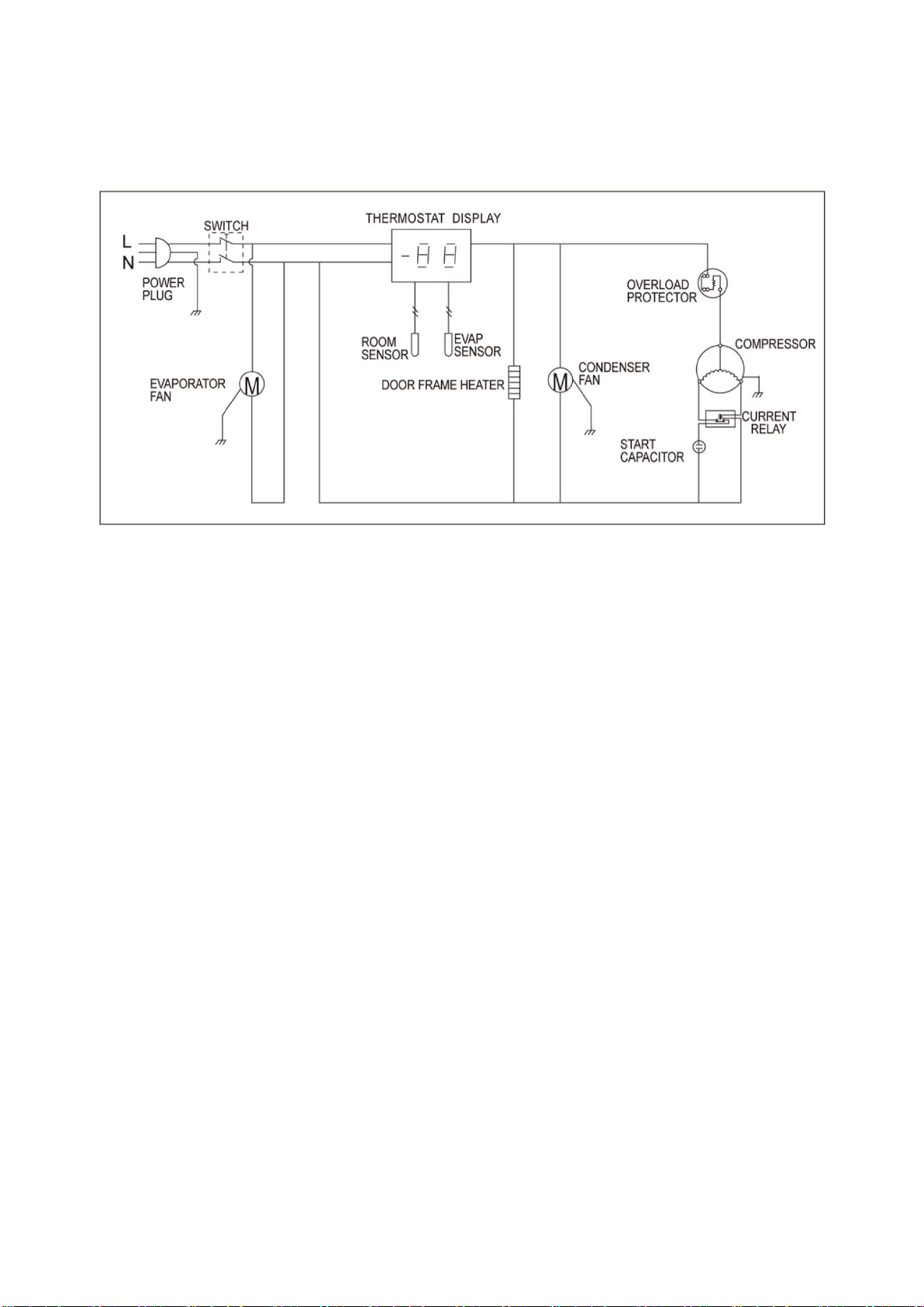
2. WIRING DIAGRAM
2-1. REFRIGERATOR: PSU28-8
3. PARTS DETAILS
3-1. BOTTOM PANEL
3-2. REFRIGERATION COMPARTMENT
3-4. DOOR
3-5. COOLING COMPARTMENT
4. MAIN COMPONENTS
4-1. COMPRESSOR
4-2. COMPRESSOR RELAY
4-3. CONDENSER DRYER
4-4. CAPACITOR
4-5. EVAPORATOR FAN MOTOR
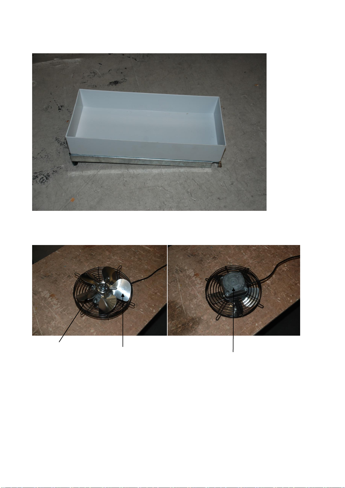
4-6. CONDENSER FAN MOTOR
4-7. EVAPORATOR DEFROST HEATER
4-8. LAMP
4-9. THERMOSTAT
5. ELECTRONIC CONTROLLER INSTRUCTION
5-1. REFRIGERATOR CONTROLLER
5-1-1. DIXELL PARAMETER FOR REFRIGERATOR
5-1-2. HOW TO USE THE CONTROLLER
6. REPLACEMENT OF MAIN COMPONENTS
6-1. FRONT PANEL PARTS
6-2. DOOR CHANGING
6-3. REFRIGERATION COMPARTMENT PARTS
6-4. CONDENSING UNIT