Sauder Orchard Hills 418649 User manual

NOTE: THIS INSTRUCTION
BOOKLET CONTAINS IMPORTANT
SAFETY INFORMATION.
PLEASE READ AND KEEP FOR
FUTURE REFERENCE.
English pg 1-26
Français pg 27-29
Español pg 30-32
Lot # 371267 04/10/15
Purchased: __________________
Be sure to give us a ring before
making any returns. 1-800-523-3987
Computer Desk with Hutch
Orchard Hills Collection | Model 418649
Need help? Visit Sauder.com to view video assembly tips or chat with a live rep.
Prefer the phone? Call 1-800-523-3987.
Share your journey!
sauder.com
For things 'n such.

Table of Contents Assembly Tools Required
2-3
4-5
6-26
27-29
30-32
33-34
35
Part Identification
Hardware Identification
Assembly Steps
Français
Español
Safety
Warranty
Hammer
Not actual size
No. 2 Phillips Screwdriver
Tip Shown Actual Size
Skip the power trip.
This time.
418649 www.sauder.com/servicesPage 2
Part Identification
åWhile not all parts are labeled, some of the parts will have a label or an inked letter on the edge
to help distinguish similar parts from each other. Use this part identification to help identify similar parts.
A RIGHT END (1)
B LEFT END (1)
C HUTCH RIGHT END (1)
D HUTCH LEFT END (1)
E UPRIGHT (1)
F HUTCH UPRIGHT (1)
G TOP (1)
H HUTCH TOP (1)
I MODESTY PANEL (1)
J BOTTOM (1)
K UPPER BACK (1)
L LOWER BACK (1)
M ADJUSTABLE SHELF (1)
N SMALL ADJUSTABLE SHELF (2)
O KEYBOARD SHELF (1)
P DOOR (1)
Q DRAWER FRONT (1)
V TOP MOLDING (1)
W DESK END MOLDING (1)
X HUTCH END MOLDING (2)
Y MOLDING (1)
Z BASE (1)
D16 RIGHT DRAWER SIDE (1)
D17 LEFT DRAWER SIDE (1)
D152 DRAWER BACK (1)
D956 DRAWER BOTTOM (1)

Part Identification Now you know
our ABCs.
418649www.sauder.com/services Page 3
A
B
C
D
E
F
G
H
I
J
K
L
M
N
O
P
Q
V
W
X
Y
Z
X
N
D17
D152
D956 D16

Hardware Identification
åScrews are shown actual size. You may receive extra hardware with your unit.
418649 www.sauder.com/servicesPage 4
35GA CABINET RIGHT - 1 35GB CABINET LEFT - 1 35GC DRAWER RIGHT - 1 35GD DRAWER LEFT - 1
35AW CABINET RIGHT - 1 35AY DRAWER RIGHT - 1 35AZ DRAWER LEFT - 1
35AX CABINET LEFT - 1
HIDDEN CAM - 16
1F CAM DOWEL - 16
2F ANGLE BRACKET - 14
27G
HINGE - 2
5H
RAIL BRACKET - 2
45G
CORD CLIP - 1
4P
KNOB - 1
116K BACKPLATE - 1
120K
10A SLIDE CAM - 2
CAM COVER - 4
12P
FELT DISC CARD - 1
1M
METAL PIN - 17
1R RUBBER SLEEVE - 12
2R
PULL - 1
123K121K PULL MOUNT- 2 NAIL - 49
1N

Hardware Identification
åScrews are shown actual size. You may receive extra hardware with your unit.
418649www.sauder.com/services Page 5
BLACK 1-7/8" FLAT HEAD SCREW - 8
2S
SILVER 1-1/8" FLAT HEAD SCREW - 4
10S
BLACK 1-1/8" MACHINE SCREW - 1
21S
18S BROWN 1" FLAT HEAD SCREW - 4 SILVER 3/4" MACHINE SCREW -2
20S
GOLD 9/16" LARGE HEAD SCREW - 40
5S
3S GOLD 5/16" FLAT HEAD SCREW -12
30S BLACK 1-9/16" FLAT HEAD SCREW - 4

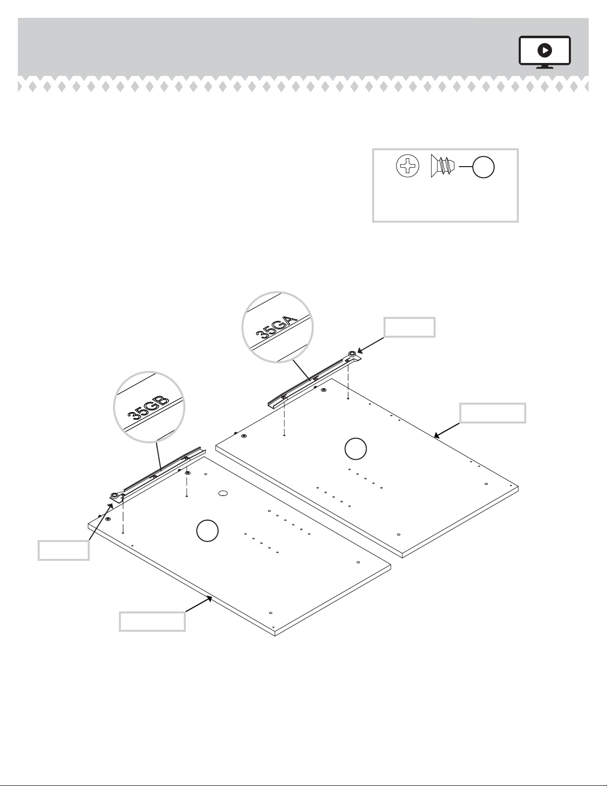
Step 1 Look for this icon. It means a
video assembly tip is available at
www.sauder.com/services/tips
å Assemble your unit on a carpeted floor or on the empty carton
to avoid scratching your unit or the floor.
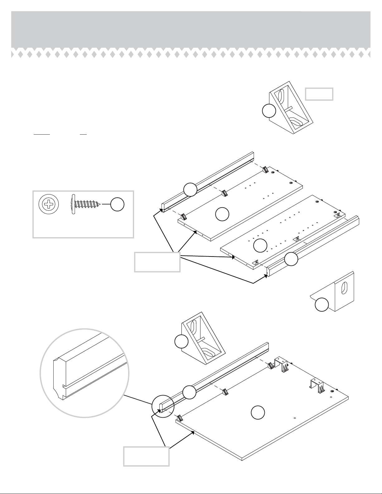
å Push sixteen HIDDEN CAMS (1F) into the ENDS (A and B),
HUTCH ENDS (C and D), UPRIGHT (E), MODESTY PANEL (I),
and BOTTOM (J). Then, insert the metal end of a CAM
DOWEL (2F) into each HIDDEN CAM.
418649 www.sauder.com/servicesPage 6
Arrow
1F
2F
(16 used)
Arrow
1F
2F
Insert the metal end of the CAM
DOWEL into the HIDDEN CAM.
Arrow
Do not tighten the HIDDEN CAMS in this step.
A
B
C
D
E
I
J

å Fasten the RAIL BRACKETS (45G) to the LEFT END (B).
Use four GOLD 9/16" LARGE HEAD SCREWS (5S).
Step 2
418649www.sauder.com/services Page 7
GOLD 9/16" LARGE HEAD SCREW
(4 used in this step)
5S
45G
B

Step 3
å Fasten the TOP MOLDING (V) to the HUTCH TOP (H).
Use four SILVER 1-1/8" FLAT HEAD SCREWS (10S).
å NOTE: Do not overtighten the SCREWS.
418649 www.sauder.com/servicesPage 8
V
H
Curved edge
SILVER 1-1/8" FLAT HEAD SCREW
(4 used in this step)
10S

å Fasten nine ANGLE BRACKETS (27G) to the LEFT END (B)
and HUTCH ENDS (C and D). Use nine GOLD 9/16" LARGE
HEAD SCREWS (5S).
å Fasten the MOLDINGS (W and X) to the ENDS (B, C, and D).
Use nine GOLD 9/16" LARGE HEAD SCREWS (5S) through
the ANGLE BRACKETS and into the MOLDINGS.
å NOTE: There are no pre-drilled holes in the MOLDINGS. The
SCREWS will tighten into the grooves.
Step 4
418649www.sauder.com/services Page 9
B
X
W
C
D
X
GOLD 9/16" LARGE HEAD SCREW
(18 used in this step)
5S
(9 used)
27G
27G
27G
These edges
should be even.
These edges
should be even.

Step 5
å Fasten the CABINET RIGHT (35GA) to the RIGHT
END (A) and the CABINET LEFT (35GB) to the
UPRIGHT (E). Use four GOLD 5/16" FLAT HEAD
SCREWS (3S) through holes #1 and #3.
418649 www.sauder.com/servicesPage 10
1
2
3
1
2
3
Roller end
Roller end
GOLD 5/16" FLAT HEAD SCREW
(4 used in this step)
3S
A
E
Finished edge
Finished edge
Surface with
HIDDEN CAMS
Surface with
HIDDEN CAMS

å Fasten the CABINET RIGHT (35AW) to the UPRIGHT (E)
and the CABINET LEFT (35AX) to the LEFT END (B). Use
four GOLD 5/16" FLAT HEAD SCREWS (3S ).
Step 6
418649www.sauder.com/services Page 11
Roller end
Finished edge
Roller end
GOLD 5/16" FLAT HEAD SCREW
(4 used in this step)
3S
B
E
Surface with
HIDDEN CAMS Surface without
HIDDEN CAMS

Step 7
å Insert two METAL PINS (1R) into the holes in the
HUTCH TOP (H).
å Push the HUTCH UPRIGHT (F) onto the METAL PINS in
the HUTCH TOP (H).
å Fasten the HUTCH ENDS (C and D) to the HUTCH
TOP (H). Tighten four HIDDEN CAMS.
418649 www.sauder.com/servicesPage 12
Start Tighten
Arrow
Minimum
190 degrees
Caution
Risk of damage or
injury. HIDDEN CAMS
must be completely
tightened. HIDDEN
CAMS that are not
completely tightened
may loosen, and parts
may separate. To
completely tighten:
Arrow
Maximum
210 degrees
D
H
F
C
V
Finished edge
1R
Surface with
HIDDEN CAMS
Surface without
HIDDEN CAMS

å Fasten the TOP (G) to the HUTCH ENDS (C and D) and
HUTCH UPRIGHT (F). Use six BLACK 1-7/8" FLAT
HEAD SCREWS (2S).
Step 8
418649www.sauder.com/services Page 13
D
G
F
C
Curved edge
BLACK 1-7/8" FLAT HEAD SCREW
(6 used in this step)
2S
Surface with
more holes
Do not stand the unit upright without the
BACK fastened. The unit may collapse.
Caution

Step 9
å Insert a METAL PIN (1R) into the hole in the TOP (G).
å Fasten the RIGHT END (A) to the TOP (G). Tighten two
HIDDEN CAMS.
å NOTE: Be sure the METAL PIN in the TOP inserts into the
RIGHT END.
å Fasten the BOTTOM (J) to the RIGHT END (A). Tighten
two HIDDEN CAMS.
418649 www.sauder.com/servicesPage 14
1R
G
A
J
Surface
with
HIDDEN
CAMS
Finished edge
This hole must be here.
Arrow
Minimum
190 degrees
Maximum
210 degrees

å Insert a METAL PIN (1R) into the hole in the TOP (G).
å Fasten the UPRIGHT (E) to the TOP (G). Tighten two
HIDDEN CAMS.
å NOTE: Be sure the METAL PIN in the TOP inserts into
the UPRIGHT.
å Fasten the BOTTOM (J) to the UPRIGHT (E). Tighten two
HIDDEN CAMS.
Step 10
418649www.sauder.com/services Page 15
1R
GEJ
Finished edge
Arrow
Minimum
190 degrees
Maximum
210 degrees

Step 11
å Fasten five ANGLE BRACKETS (27G) to the RIGHT END (A), UPRIGHT (E),
and BOTTOM (J). Use five GOLD 9/16" LARGE HEAD SCREWS (5S).
å NOTE: Be sure the edges of the ANGLE BRACKETS are even with the
edges of the RIGHT END, UPRIGHT, and BOTTOM.
å Fasten the MOLDING (Y) to the RIGHT END (A) and UPRIGHT (E). Use
two GOLD 9/16" LARGE HEAD SCREWS (5S) through the ANGLE
BRACKETS and into the MOLDING.
å Fasten the BASE (Z) to the RIGHT END (A), UPRIGHT (E), and
BOTTOM (J). Use three GOLD 9/16" LARGE HEAD SCREWS (5S)
through the ANGLE BRACKETS and into the BASE.
418649 www.sauder.com/servicesPage 16
GOLD 9/16" LARGE HEAD SCREW
(10 used in this step)
5S
27G
A
J
Z
Y
E
27G
27G
27G
27G

å With someone's help, carefully turn your unit over.
å Insert a METAL PIN (1R) into the hole in the TOP (G).
å Fasten the LEFT END (B) to the TOP (G). Tighten two
HIDDEN CAMS.
å NOTE: Be sure the METAL PIN in the TOP inserts into
the LEFT END.
Step 12
418649www.sauder.com/services Page 17
1R
G
B
Arrow
Minimum
190 degrees
Maximum
210 degrees
W

Step 13
å Fasten the MODESTY PANEL (I) to the LEFT END (B).
Tighten two HIDDEN CAMS.
å Fasten the MODESTY PANEL (I) to the UPRIGHT (E). Use
two BLACK 1-7/8" FLAT HEAD SCREWS (2S).
418649 www.sauder.com/servicesPage 18
Arrow
Minimum
190 degrees
Maximum
210 degrees
BLACK 1-7/8" FLAT HEAD SCREW
(2 used in this step)
2S
E
B
I
Notch
Surface with
HIDDEN CAMS

å Unfold the UPPER BACK (K) and lay both BACKS (K and L) over
your unit. The notches in the UPPER BACK (K) should fit into the
notches in the LOWER BACK (L).
å Make equal margins along all four edges of the BACKS (K and L).
Push on opposite corners of your unit if needed to make it "square".
å Fasten the BACKS (K and L) to your unit using the NAILS (1N).
å NOTE: Be sure to tap NAILS into the holes that line up over the
HUTCH UPRIGHT (F).
å NOTE: Perforations have been provided for access through the
BACK. Carefully cut out the holes needed.
Step 14
418649www.sauder.com/services Page 19
Do not stand the unit upright without the
BACK fastened. The unit may collapse.
Caution
Unfinished
surface
These holes must line up over
the HUTCH UPRIGHT (F).
NAIL
(49 used in this step)
1N
K
L
Notch

Step 15
å Fasten the HINGES (5H) to the DOOR (P). Use four GOLD
9/16" LARGE HEAD SCREWS (5S).
418649 www.sauder.com/servicesPage 20
GOLD 9/16" LARGE HEAD SCREW
(4 used in this step)
5S
P
5H