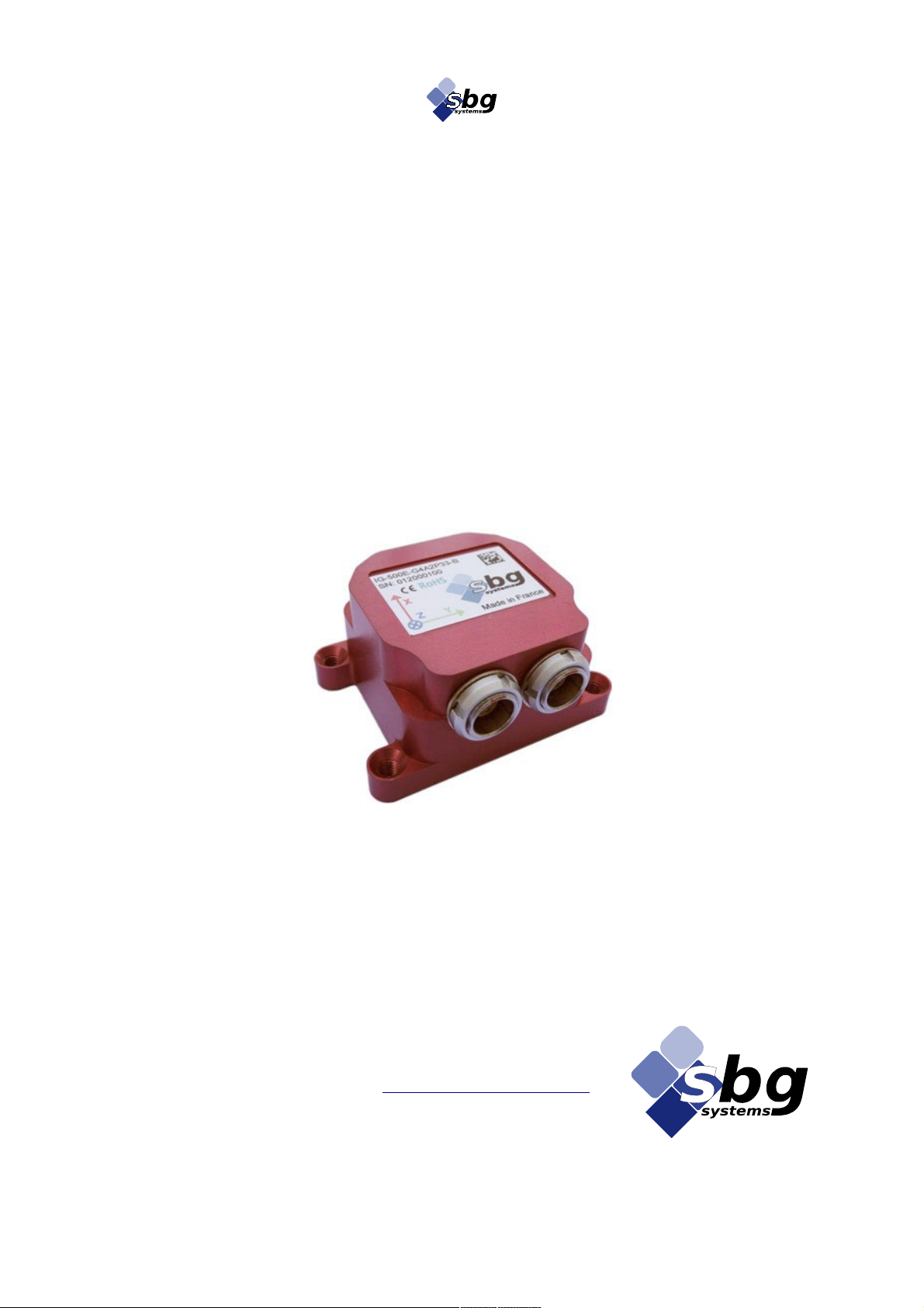
IG-500E IG Device Integration Manual
5. IG-500E specific settings an behaviors with IG-Devices
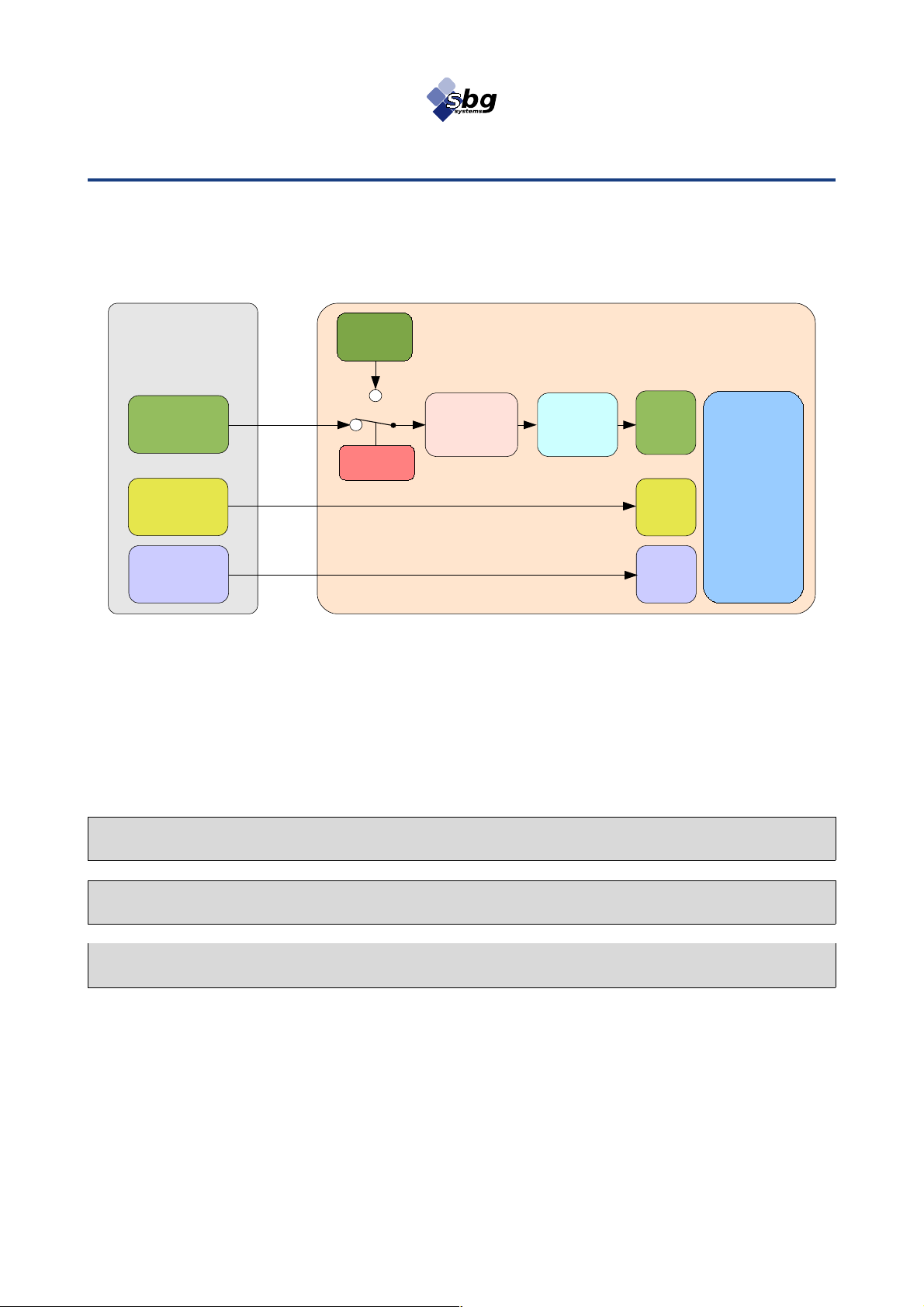
When you configure the IG-500E to accept ai ing ata from an IG-Device, some specific settings,
only relate to IG-Devices, become available.
For more etails, please have a look at the Appen ix: Low level comman s efinitions.
.1. Magnetometers management
When the remote magnetometers are use as a hea ing source, all internal magnetometer outputs
are replace by remote magnetometer outputs.
This behavior affects all outputs linke to the magnetometers:
•Magnetometers Raw Data (if the remote evice oes not output magnetometers Raw ata,
this output is set to 0).
•Calibrate magnetometer values
•Mag Calib. Data. : These ata are use for magnetometers calibration.
Therefore, when you run a har an soft iron calibration, the result store in the IG-500E
correspon s to the remote magnetometer calibration.
Note: When the magnetic source is changed, the magnetic calibration present in IG-500E
memory becomes inconsistent ith the actual magnetometer used and must be performed again
for proper operation.
.2. GPS altitude reference
The IG-Device integration oes not allow you to configure irectly the GPS altitu e reference
(height above ellipsoi or above mean sea level). Instea of that, user shoul configure the remote
IG-Device to output the esire altitu e format.
.3. IG-Device orientation offset
To work correctly, both the IG-500E an the attache IG-Device shoul use the same coor inate
frame.
When you know exactly the orientation offset between the IG-500E an the remote IG-Device,
then, you shoul use this feature.
SBG Systems 8/11 IG500EIIDG.3