SBS CM4 User manual

Artisan Technology Group is your source for quality
new and certied-used/pre-owned equipment
• FAST SHIPPING AND
DELIVERY
• TENS OF THOUSANDS OF
IN-STOCK ITEMS
• EQUIPMENT DEMOS
• HUNDREDS OF
MANUFACTURERS
SUPPORTED
• LEASING/MONTHLY
RENTALS
• ITAR CERTIFIED
SECURE ASSET SOLUTIONS
SERVICE CENTER REPAIRS
Experienced engineers and technicians on staff
at our full-service, in-house repair center
WE BUY USED EQUIPMENT
Sell your excess, underutilized, and idle used equipment
We also offer credit for buy-backs and trade-ins
www.artisantg.com/WeBuyEquipment
REMOTE INSPECTION
Remotely inspect equipment before purchasing with
our interactive website at www.instraview.com
LOOKING FOR MORE INFORMATION?
Visit us on the web at www.artisantg.com for more
information on price quotations, drivers, technical
specications, manuals, and documentation
Contact us: (888) 88-SOURCE | sales@artisantg.com | www.artisantg.com
SM
View
Instra
Rev F
Preliminary
Edition
Artisan Technology Group - Quality Instrumentation ... Guaranteed | (888) 88-SOURCE | www.artisantg.com

CM4 User’s Guide—SBS Technologies ii
Preliminary
Copyright
Copyright © 2005 - SBS Technologies, Inc. All rights reserved.
CM4 User's Manual - Rev. F
This document and its contents are provided as is, with no warranties of any kind, whether express or implied, includ-
ing warranties of design, merchantability, and fitness for a particular purpose, or arising from any course of dealing,
usage, or trade practice.
The content of this manual is furnished for informational use only and is subject to change without notice. Reverse
engineering of any SBS product is strictly prohibited.
In no event will SBS be liable for any lost revenue or profits or other special, indirect, incidental and consequential
damage, even if SBS has been advised of the possibility of such damages, as a result of the usage of this document
and the product that this document describes.
SBS shall have no liability with respect to the infringement of copyrights, trade secrets, or any patents by this docu-
ment or any part thereof.
SBS and the SBS logo are trademarks of SBS Technologies.
Intel is a trademark of Intel Corporation.
IBM and PowerPC are trademarks of International Business Machines (IBM).
CompactPCI is a trademark of the PCI Industrial Computer Manufacturers Group.
VxWorks is a trademark of WindRiver Systems, Inc.
SBS Technologies
7401 Snaproll
Albuquerque, NM 87109-4358
Tel 505.875.0600 Fax 505.478.1400
Document #:70000340-800 Rev. E and 70000345-800 Rev. E
Conventions
The following conventions are used in this user’s guide:
• Signal names are designated with all capital letters (e.g. SYSEN#)
• Signal names followed by the pound sign (#) are active-low (e.g. SYSEN#)
• Data addresses written in hexadecimal are designated with the prefix 0x (e.g. 0xF000_0000)
Artisan Technology Group - Quality Instrumentation ... Guaranteed | (888) 88-SOURCE | www.artisantg.com

CM4 User’s Guide—SBS Technologies iii
Preliminary
Table of Contents
Chapter 1: Introduction
1.1 Overview ...............................................................................................................1-1
1.2 Specification .........................................................................................................1-3
1.3 Block Diagram ......................................................................................................1-4
1.4 Technical Support .................................................................................................1-5
1.5 Related Documents ...............................................................................................1-5
Chapter 2: Getting Started
2.1 What is included ...................................................................................................2-1
2.2 Equipment Needed ................................................................................................2-1
2.3 Power ....................................................................................................................2-2
2.4 Installation ............................................................................................................2-3
Chapter 3: Board Description
3.1 Physical Description .............................................................................................3-1
3.2 Power ....................................................................................................................3-1
3.3 Connector Locations .............................................................................................3-2
3.4 Front Panel ............................................................................................................3-2
3.5.1 CompactPCI Connectors ...........................................................................3-3
3.5.2 PMC Connectors ........................................................................................3-5
3.5.3 JTAG/COP Port (P1100) ...........................................................................3-7
3.6 Memory/X-bus ......................................................................................................3-8
3.7 Memory Map ......................................................................................................3-10
3.7.1 I/O Devices ..............................................................................................3-11
3.8 PCI Arbitration ...................................................................................................3-11
3.9 PCI IDSEL ..........................................................................................................3-12
3.10 Serial I/O Communications ................................................................................ 3-12
3.11 Digital I/O Communications ............................................................................... 3-14
Artisan Technology Group - Quality Instrumentation ... Guaranteed | (888) 88-SOURCE | www.artisantg.com

iv CM4 User’s Guide—SBS Technologies
Preliminary
3.12 Ethernet I/O Communications ............................................................................3-16
3.13 System Controller vs. Peripheral Operation .......................................................3-16
3.14 Reset Circuitry ....................................................................................................3-17
3.14.1 Hard Resets ..............................................................................................3-17
3.14.2 Soft Resets ...............................................................................................3-20
3.14.3 PCI Resets ................................................................................................3-20
3.14.4 Watchdog Timer ......................................................................................3-21
3.15 Interrupt Circuitry ...............................................................................................3-22
3.15.1 PCI Interrupts ...........................................................................................3-22
3.15.2 On-board Interrupts ..................................................................................3-25
3.16 Clock Circuitry ...................................................................................................3-26
3.16.1 24MHz and 14.318MHz Clocks ..............................................................3-26
3.16.2 Real-Time Clock ......................................................................................3-26
3.16.3 Tsi107 Clock Distribution .......................................................................3-27
3.16.4 PCI 6254 PCI Bridge Clock Operation—Transparent Mode ..................3-29
3.16.5 PCI 6254 PCI Bridge Clock Operation—Non-Transparent Mode ..........3-29
Chapter 4: Components
4.1 Component Location .............................................................................................4-1
4.2 Processors .............................................................................................................4-2
4.3 Tsi107 Host Bridge ...............................................................................................4-3
4.3.1 System Bus Interface .................................................................................4-3
4.3.2 Memory Controller and Bus Interface .......................................................4-3
4.3.3 PCI Bus Interface .......................................................................................4-3
4.3.4 Interrupt Controller ....................................................................................4-3
4.4 PCI 6254 PCI Bridge ............................................................................................4-4
4.5 SDRAM ................................................................................................................4-4
4.6 Flash Memory .......................................................................................................4-4
4.6.1 Boot Flash ..................................................................................................4-4
4.6.2 Extended Flash ...........................................................................................4-4
4.7 Decoder CPLD ......................................................................................................4-5
4.8 82559ER Ethernet Controller ...............................................................................4-5
4.9 ST16C2550 Dual Channel UARTs .......................................................................4-5
4.10 STK14C88 NVSRAM ..........................................................................................4-6
4.11 DS1685 Real-Time Clock .....................................................................................4-6
Chapter 5: CPLD Registers
5.1 Watchdog Control Register ..................................................................................5-1
Artisan Technology Group - Quality Instrumentation ... Guaranteed | (888) 88-SOURCE | www.artisantg.com

CM4 User’s Guide—SBS Technologies v
Preliminary
5.2 MCP Ticker Control Register ...............................................................................5-2
5.3 MCP Ticker Reset Register ..................................................................................5-2
5.4 Interrupt Status Register .......................................................................................5-3
5.5 Interrupt Mask Register ........................................................................................5-4
5.6 Status Input Port Register .....................................................................................5-5
5.7 Status Output Port Register ...................................................................................5-6
5.8 CPLD Version Register ........................................................................................5-6
5.9 Digital I/O Registers .............................................................................................5-7
5.9.1 DOUT Register ..........................................................................................5-7
5.9.2 DOUTEN Register .....................................................................................5-8
5.9.3 DINQ Register ...........................................................................................5-8
5.10 DI/O Interrupt Status Register ..............................................................................5-9
5.11 DI/O Interrupt Mask Register .............................................................................5-10
Chapter 6: Customer Service
6.1 Introduction ...........................................................................................................6-1
6.2 Updated User Guides and Data Sheets .................................................................6-1
6.3 Customer Service ..................................................................................................6-2
6.4 Warranty Information ...........................................................................................6-2
6.4.1 Warranty ....................................................................................................6-2
6.4.2 Non-Warranty Terms and Conditions ........................................................6-3
6.5 Return Material Authorization (RMA) .................................................................6-3
6.6 Documentation Feedback Form ............................................................................6-5
Index
Artisan Technology Group - Quality Instrumentation ... Guaranteed | (888) 88-SOURCE | www.artisantg.com

CM4 User’s Guide—SBS Technologies vii
Preliminary
List of Figures
Figure 1-1 Convection-cooled configuration.............................................................................1-2
Figure 1-2 Conduction-cooled configuration ............................................................................1-2
Figure 1-3 CM4 Block diagram.................................................................................................1-4
Figure 2-1 Power regulation recommendations.........................................................................2-2
Figure 3-1 Connector locations (convection-cooling version)..................................................3-2
Figure 3-2 Front panel (convection-cooled configuration)........................................................3-2
Figure 3-3 JTAG/COP port (P1100)..........................................................................................3-7
Figure 3-4 Memory/X-bus network...........................................................................................3-9
Figure 3-5 Serial port circuitry ................................................................................................3-13
Figure 3-6 Digital I/O circuit (digital port 0)...........................................................................3-15
Figure 3-7 Ethernet circuitry....................................................................................................3-16
Figure 3-8 PCI 6254 PCI Bridge in transparent and non-transparent mode............................3-17
Figure 3-9 Power-up reset circuitry.........................................................................................3-18
Figure 3-10 Reset circuitry........................................................................................................3-19
Figure 3-11 PCI reset when CM4 is a system controller...........................................................3-21
Figure 3-12 PCI reset when CM4 is a peripheral card ..............................................................3-21
Figure 3-13 Interrupt circuitry...................................................................................................3-23
Figure 3-14 Decoder CPLD PCI interrupt circuitry ..................................................................3-24
Figure 3-15 Decoder CPLD interrupt circuitry..........................................................................3-25
Figure 3-16 CPU interrupt circuitry...........................................................................................3-26
Figure 3-17 Primary clock circuitry...........................................................................................3-27
Figure 3-18 PCI clock circuitry.................................................................................................3-28
Figure 3-19 cPCI clock circuitry ...............................................................................................3-30
Figure 4-1 CM4 components (front view).................................................................................4-1
Artisan Technology Group - Quality Instrumentation ... Guaranteed | (888) 88-SOURCE | www.artisantg.com

CM4 User’s Guide—SBS Technologies viii
Preliminary
Figure 4-2 CM4 components (back side)...................................................................................4-2
Artisan Technology Group - Quality Instrumentation ... Guaranteed | (888) 88-SOURCE | www.artisantg.com

CM4 User’s Guide—SBS Technologies ix
Preliminary
List of Tables
Table 3-1 Processor voltages.................................................................................................... 3-1
Table 3-2 CompactPCI connector P7201 pin assignments ...................................................... 3-3
Table 3-3 CompactPCI connector P7202 pin assignments ...................................................... 3-4
Table 3-4 PMC connectors P7101 and P7102 pin assignments............................................... 3-5
Table 3-5 PMC-P7103 pin assignments................................................................................... 3-6
Table 3-6 JTAG/COP port pin assignments............................................................................. 3-7
Table 3-7 Tsi107 memory map—processor view .................................................................. 3-10
Table 3-8 Tsi107 memory map—PCI bus master view......................................................... 3-11
Table 3-9 X-bus I/O address map........................................................................................... 3-11
Table 3-10 PCI bus arbitration ................................................................................................. 3-11
Table 3-11 PCI IDSEL configuration registers........................................................................ 3-12
Table 3-12 Serial port addresses............................................................................................... 3-12
Table 3-13 Rotated PMC interrupt connections....................................................................... 3-22
Table 3-14 Processor system clocks......................................................................................... 3-27
Table 4-1 Processor parameters................................................................................................ 4-2
Table 4-2 Real-Time Clock time, calendar and alarm data modes .......................................... 4-7
Artisan Technology Group - Quality Instrumentation ... Guaranteed | (888) 88-SOURCE | www.artisantg.com

CM4 User’s Guide—SBS Technologies 1-1
Preliminary
Chapter 1: Introduction
1.1 Overview
The CM4 is a 3U CompactPCI Single Board Computer (SBC) designed for network switching,
routing, and front-end processing applications. It is available with multiple processor options and
offers the flexibility of functioning as a system controller or peripheral card. The CM4 is available
in configurations for convection-cooled or conduction-cooled environments.
The CM4 offers two PowerPC Reduced Instruction Set Computer (RISC) processor options:
• MPC755—400MHz
• MPC7410—500MHz
Each processor includes 32KB L1 instruction and 32KB L1data caches. The MPC755 comes with
1MB of backside L2 cache; the MPC7410 processor comes with 2MB of backside L2 cache.
The CM4 implements the Tsi107 Host Bridge (replacing the MPC107 PCI Bridge chip) that
includes a 64-bit 100MHz system bus interface, a memory controller with a 64-bit 100MHz mem-
ory interface, and a 32-bit 33MHz PCI interface. The memory interface accesses up to four 16M x
16 SDRAM chips for a total on-board system memory of 128MB to 512MB. Error Checking and
Correction (ECC) is also included. It also accesses four 64Mb StrataFlash devices for a total
on-board flash memory of 64MB. The memory bus also connects with the X-bus to access the
8MB StrataFlash boot flash, 32KB NVSRAM, Real Time Clock, and Decoder CPLD.
The Tsi107 Host Bridge also provides a 32-bit PCI bus interface that connects with the
10/100Mbps 82559ER Ethernet Controller, PCI 6254 PCI Bridge, and a single PMC site.
The 82559ER Ethernet Controller with integrated Medial Access Control (MAC) and physical
layer (PHY) provides a 10Base-T and 100Base-TX network communications interface through
the cPCI P7202 (P2) connector to the backplane or an optional CM4 Transition Module (TM),
which provides either a RJ-45 connector mounted on a rear panel or a surface-mounted connector.
The CM4 includes two ST16C2550 Dual Channel UART Transceivers that provide two RS-232
serial ports and two RS-422/485 serial ports. All four channels operate in full-duplex mode and
include 16 bytes of FIFO transmit and 16 bytes of FIFO receive memory.
In addition to serial and Ethernet I/O, the CM4 offers four programmable digital I/O channels that
can be used for manufacturing process control lines.
The PCI 6254 PCI Bridge connects the PCI bus (bus 0) to the cPCI backplane (bus1). Because the
CM4 can function as a system controller or a peripheral card, the PCI 6254 PCI Bridge (formerly
Artisan Technology Group - Quality Instrumentation ... Guaranteed | (888) 88-SOURCE | www.artisantg.com

1-2 CM4 User’s Guide—SBS Technologies
Introduction
Preliminary
HB6) must change how it handles data and PCI signals according to the mode in which the CM4
is operating. When the CM4 is a system controller, the PCI 6254 is in transparent mode, which
means the PCI host—the Tsi107 Host Bridge—looks through the PCI 6254 to the backplane, to
the PCI devices on other peripheral cards throughout the system. When the CM4 is a peripheral
card, the PCI 6254 PCI Bridge is in non-transparent mode, which means that it sees the Tsi107
Host Bridge as PCI device, but cannot look past it to the backplane. This affects how the PCI
6254 handles interrupts and reset signals.
The CM4 incorporates additional flexibility with a PMC site for adding additional I/O capability
with over 30 user-defined I/O lines.
The CM4 offers configurations for either convection-cooled or conduction-cooled environment.
Figure 1-2 Conduction-cooled configuration
Figure 1-1 Convection-cooled configuration
Artisan Technology Group - Quality Instrumentation ... Guaranteed | (888) 88-SOURCE | www.artisantg.com

CM4 User’s Guide—SBS Technologies 1-3
Introduction
Preliminary
1.2 Specification
Processor
• MPC755 (400MHz)
• MPC7410 (500MHz)
• On-chip L1 cache (32KB instruction,
32KB data, all processors)
Power Requirements
• +3.3V
•+5V
• ±12V (for installed PMC only)
Software
• BSP with VxWorks O/S
L2 Cache
• MPC755—1MB
• MPC7410—2MB
Environmental Requirements*
Tsi107 Host Bridge
• 64-bit 100MHz system bus interface
• 32-bit 33MHz PCI bus interface
• Memory controller with 64-bit
100MHz memory interface
• 2 DMA controllers
Memory
• 72-bit (w/ECC)100MHz SDRAM
128–512MB supported
• 64-bit 64MB flash memory
• 8-bit 8MB boot flash
• 32kB non-volatile SRAM
automatic data transfer to and from
EEPROM
Communications
• Serial ports—asynchronous
full-duplex 16550-compatible
UARTs
2 RS-232 ports
2 RS-422/485 ports
• Fast Ethernet—82559ER
10Base-T
100Base-TX
Auto-negotiation
•DigitalI/O
4 register-controlled ports
Warranty
• Two year warranty
• Operating temperature
Standard:
Extended: 0° to +70°C
-40° to +85°C
• Storage temperature:
Standard:
Extended: -40° to +85°C
-55° to +105°C
• Humidity: 5–95% @40°C
• Altitude:
Operating:
Storage: 15,000 ft. (4.5Km)
40,000 ft. (12Km)
• Shock:
C-style:
R-style:
N-style:
12g/6ms
20g/6ms
100g/6ms
• Vibration:
C-style:
R-style:
N-style:
2g rms/5 to 100Hz
2g rms/5 to 2KHz
14g rms/5 to 2KHz
(N-style: 30 min-
utes each axis)
* All values under typical conditions w/o
PMC module installed.
Artisan Technology Group - Quality Instrumentation ... Guaranteed | (888) 88-SOURCE | www.artisantg.com
1-4 CM4 User’s Guide—SBS Technologies
Introduction
Preliminary
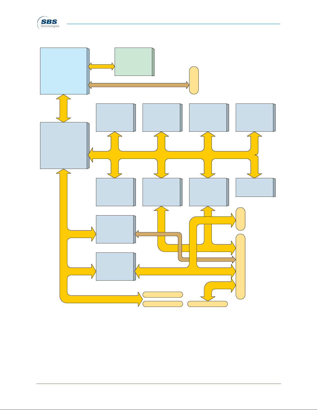
1.3 Block Diagram
Figure 1-3 CM4 Block diagram
NOTE: The Memory/X-bus represents a network of buses shown in greater detail in “Mem-
ory/X-bus” on page 3-8.
Processor
PPC 755
PPC 7410
Tsi107
Host Bridge
L2
Cache
SDRAM
4 pcs.
StrataFlash
4 pcs.
Boot
Flash
RTCST16C2550
UART
Serial I/O
Decoder
CPLD
82559ER
Ethernet
PCI 6254
PCI
Bridge
P7102
P7101
PCI bus
CPCI_P7201
CPCI_P7202
PMC Site
P7103
ST16C2550
UART
Serial I/O
Memory/X-bus
JTAG/COP
P1100
STK14C88
NVSRAM
PCI bus
Artisan Technology Group - Quality Instrumentation ... Guaranteed | (888) 88-SOURCE | www.artisantg.com

CM4 User’s Guide—SBS Technologies 1-5
Introduction
Preliminary
1.4 Technical Support
Most issues can be resolved by referring to this manual. If any problems cannot be resolved,
please contact SBS Technical Support by:
• Telephone: (919) 851-1101 (ask for technical support)
• Fax.: (919) 851-2844
For more information, refer to “Customer Service” on page 6-2.
1.5 Related Documents
For more information on CM4 components, refer to the following documents:
Components
• MPC755 RISC Processor Hardware Specification—Motorola, Inc., MPC750EC/D
Rev. 6, September 2002
• MPC7410 RISC Microprocessor Hardware Specification—Motorola, Inc.,
MPC7410EC/D Rev. 0.3, April 2001
• MPC107 PCI Bridge/Memory Controller User’s Manual—Motorola, Inc.,
MPC107UM/D Rev. 0, November 2000
• Tsi107™ PowerPC™ Host Bridge User’s Manual—Tundra Semiconductor Corpora-
tion,80C2000_MA001_03, January 2004
• PCI 6254 (HB6) Dual Mode Universal PCI-to-PCI Bridge DataBook—PLX Tech-
nology, Inc., Version 2.0, May 2003
• 3Volt Synchronous Intel StrataFlash® Memory Data Sheet—Intel® Corporation,
Order number 290737-004, February 2002
• 82559ER Fast Ethernet PCI Controller Data Sheet—Intel® Corporation, Order num-
ber 714682-002, Revision 1.3, March 2001
• XC95144XL High Performance CPLD—Xilinx, Inc., Preliminary Production Speci-
fication - Version 1.2, November 1998
• STK14C88 32K x 8 AutoStore™ nvSRAM QuantumTrap™ CMOS Nonvolatile
Static RAM—Simtek Corporation, Document Control # ML0014 rev. 0.0,
December 2002
• ST16C2550 3.3V and 5V DUART with 16-bit FIFO—EXAR Corporation, Rev. 4.1,
March 2002
• DS1685/DS1687 3V/5V Real-Time Clock—Dallas Semiconductor Corporation,
DS1685/DX1687
Artisan Technology Group - Quality Instrumentation ... Guaranteed | (888) 88-SOURCE | www.artisantg.com

1-6 CM4 User’s Guide—SBS Technologies
Introduction
Preliminary
Specifications
• PowerPC Reference Platform Specification—IBM Corporation, Version 1.1
• PICMG 2.0 CompactPCI Specification—Rev 3.0, October 1999
• PICMG 2.3 PMC on CompactPCI—Rev. 1.0, August 1998
• PCI Local Bus Specification—PCI Special Interest Group, Revision 3.0
• Draft Standard for Common Mezzanine Card Family—CMC, IEEE Standards
Department, P1386/Draft 2.0
• Draft Standard Physical and Environmental layers for PCI Mezzanine Cards—PMC,
IEEE Standards Department, P1386/Rev 1.0
1. PICMG Specifications are available to PICMG members only. SBS Technologies is not authorized to dis-
tribute copies of these specifications. More information can be found at http://www.picmg.org.
2. Data sheets from hardware components can be downloaded from individual vendors web sites.
Artisan Technology Group - Quality Instrumentation ... Guaranteed | (888) 88-SOURCE | www.artisantg.com
CM4 User’s Guide—SBS Technologies 2-1
Preliminary
Chapter 2: Getting Started
2.1 What is included
The CM4 is shipped with the following items:
• CM4 SBC printed circuit board
2.2 Equipment Needed
The following items are needed to install and operate the CM4:
• Host computer with terminal/console program
• CompactPCI-compatible chassis with system controller card installed
• CM4 Transition Module (optional) (recommended for convection-cooled applica-
tions)
• Ethernet cable
• 1:1 Serial cable
E.S.D
Caution! Always use proper Electrostatic Discharge (ESD) protection when han-
dling printed circuit boards to avoid seriously damaging components. Product han-
dlers must always be properly grounded.
Artisan Technology Group - Quality Instrumentation ... Guaranteed | (888) 88-SOURCE | www.artisantg.com

2-2 CM4 User’s Guide—SBS Technologies
Getting Started
Preliminary
2.3 Power
The CM4 is designed for +3.3V operation but will tolerate +5V. The MIC2903 DC/DC Converter
taps the +3.3V rail to provide a +2.5V line. The LTC1727 Power Monitor monitors the +3.3V and
+2.5V line.
Caution! Processor manufacturers recommend the following power restrictions for
long term product reliability.To comply with these power restrictions, it is recom-
mended the CompactPCI chassis use a dual power supply that complies with the
ATX Power Supply Design Guide, Version 1.2.
Figure 2-1 Power regulation recommendations
NOTES:
1. VCC3 (+3.3V) must not exceed VCC (+5V) by more than +0.6V for
more than 20ms at any time including power-up and power-down.
2. VCC5 (+5V) must not exceed VCC3 (+3.3V) by more than +3.6V for
more than 20ms at any time including power-up and power-down.
VCC5
VCC3
1
2
Artisan Technology Group - Quality Instrumentation ... Guaranteed | (888) 88-SOURCE | www.artisantg.com

CM4 User’s Guide—SBS Technologies 2-3
Getting Started
Preliminary
2.4 Installation
This installation procedure is a sample bootup scheme that assumes the CM4 will boot from a
CM4 BSP VxWorks image located on a network or host computer.
1. Copy the BSP from the CD ROM to a permanent storage location either on a network or
the host computer.
At a minimum the VxWorks image must be available in an FTP server location for the
CM4 during bootup.
2. Remove the CM4 from the static-safe envelope.
3. Install the CM4 in a 3U 32-bit CompactPCI-compliant chassis.
Caution! The CM4 is not compatible with a 64-bit backplane.
Convection-cooled Configuration
4. Slide the CM4 into the slot guide, applying even pressure to the front panel and lower
ejector handle. Be careful not to bend connector pins.
5. Push up on the lower extraction handle to seat the CompactPCI connectors in the back-
plane connectors. The red tab on the extraction handle should “click” when the board is
locked into the chassis.
6. Tighten the large screw on the front panel, then tighten the smaller screw embedded in the
extraction handle to secure the CM4 to the chassis.
Conduction-cooled Configuration
7. Slide the CM4 into the slot guide, applying even pressure to the upper and lower extrac-
tion levers. Be careful not to bend connector pins.
8. Use a 3/32-inch hex torque driver to tighten the top and bottom hex screws to 117-inch
ounces (0.8-newton meters).
All Configurations
9. When the CM4 has been installed in the chassis, install a serial cable from the host com-
puter to the CM4 through either the optional CM4 Transition Module or other serial port
connected to the backplane.
10. Install a Ethernet cable from the host computer or network connection to the CM4 through
either the optional CM4 Transition Module or other Ethernet port connected to the back-
plane.
11.Apply power to the chassis.
NOTE: CM4 can be installed in a system controller or peripheral slot. If the CM4 is not installed
in a system slot, a system controller card must be installed in the system slot to supply a PCI ref-
erence clock to CM4.
Artisan Technology Group - Quality Instrumentation ... Guaranteed | (888) 88-SOURCE | www.artisantg.com
2-4 CM4 User’s Guide—SBS Technologies
Getting Started
Preliminary
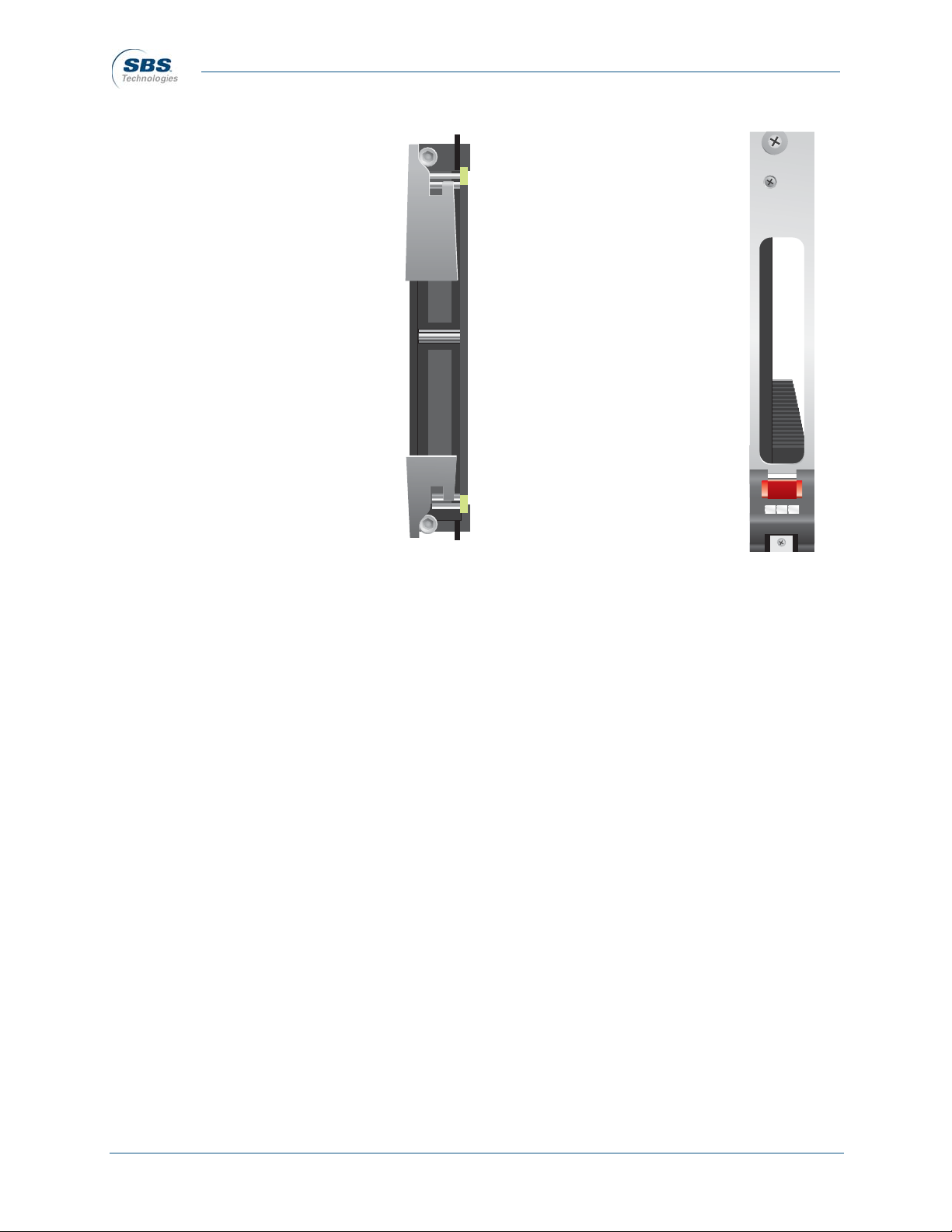
Figure 2-3 Convection-cooled
configuration
Figure 2-2 Conduction-cooled
configuration
Artisan Technology Group - Quality Instrumentation ... Guaranteed | (888) 88-SOURCE | www.artisantg.com

CM4 User’s Guide—SBS Technologies 3-1
Preliminary
Chapter 3: Board Description
3.1 Physical Description
* Highest achievable operating temperature depends on processor type, speed, and
ambient conditions (card edge temperature). Also, all temperature values are typical
conditions without PMC module installed.
3.2 Power
The CM4 inputs two voltage rails: +5V and +3.3V (see “Cau-
tion” on page 2-2). A linear regulator taps the +3.3V line and
outputs a +2.5V line. VI/O is taken from either the +3.3V for
the MPC755 processors or +2.5V for the MPC7410 processor.
The LTC1727 power monitor tracks these voltages (+3.3V and
+2.5V) within a specified range. If the +3.3V supply drifts
above or below its specified range, the power monitor will assert an interrupt (INT3V) to the
Decoder CPLD. If it is out of range for longer than 50µs, the power monitor asserts the reset out-
put (BOARD_RST#), which resets the CM4. If the +2.5V supply drifts outside its specified range,
the power monitor will assert the VCC2.5OK signal that disables the LM2636 Buck Controller,
which provides the processor core voltages. If the +2.5V supply is out of specification for longer
than 50µs, the power monitor will assert the reset output (BOARD_RST#), which resets the CM4.
BOARD_RST# will remain asserted for 200ms even if the +3.3V or +2.5V supply returns to the
specified range.
Configuration resistors on the input of the LM2636 Buck Controller set processor core voltages
(VCCP) according to the installed processor as listed in Table 3-1.
Height: 100mm (3.9 inches)
Length: 160mm (6.3 inches)
Operating temperature: -40° to 85° C (ambient)*
Storage temperature: -40° to 85° C (N-style: -55° C to 105° C)
Humidity: 10% to 95% (non-condensing)
Cooling: Forced air 200 LFM (min.)
Power (+3.3VDC ±5%): normal—1.3A (4.29W)
Power (+5VDC ±5%): normal—1.9A (9.5W)
Table 3-1 Processor voltages
Processor Core Voltage
MPC755 +2.0V
MPC7410 +1.8V
Artisan Technology Group - Quality Instrumentation ... Guaranteed | (888) 88-SOURCE | www.artisantg.com
Table of contents
Other SBS Motherboard manuals


 manual")


