SCAD TM1 User manual
SCAD TM1 and TM2 Tank Monitor Manual
Introduction
The monitor can be used with SCAD’s electronic external stick-on or internal rod sensors
for water and holding tanks and standard 240-33 Ohm or 10-180 Ohm float sensors.
Additional related information is available at www.scadtech.com/TMHelp
Included Parts
1. Monitor display
2. Wire harness
3. Inline 1 Amp fuse
4. Electronic external
sensor module
5. 60 inches of aluminum
sensor tape
6. 5 self tapping
mounting screws
Required Tools and Materials
1. Drill with 1/2 inch (13mm) drill bit.
2. 22-18 AWG butt-splice terminations (preferably
waterproof with heat shrink adhesive) and wire
termination tools
3. 22 AWG stranded wire in 3 colors preferably 3-
conductor with red blue or green and black. Must
span from the display to each sensor.
4. Isopropyl alcohol to clean any residue off the tank.
5. #1 Phillips screwdriver
Installation
Display Mounting
1. Choose a location for the monitor display that is away from weather or spilled fluids.
Be sure there is sufficient access behind the panel to route the wires.
2. Hold the display with the face toward the mounting surface and mark the location of
each of the four screw holes. Draw an X connecting the screw hole marks to
determine the center. Measure down 5/16” from the center mark and Drill a 1/2” hole.
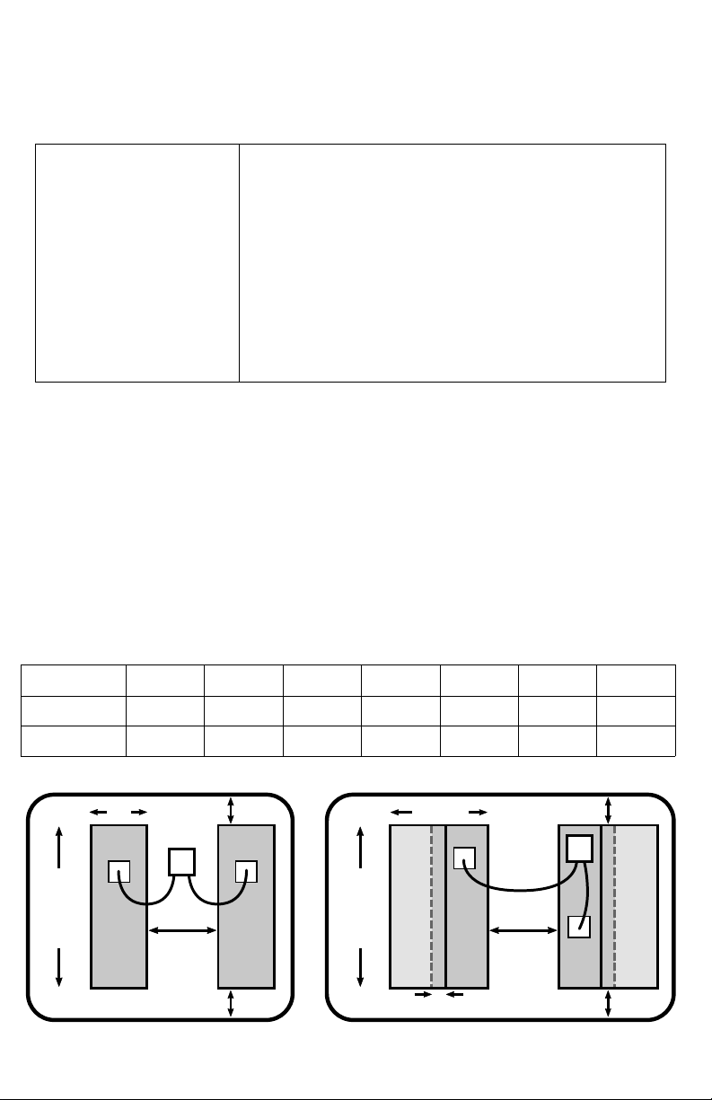
External Sensor Foil Placement for Plastic & Fiberglass Tanks
Use the table and illustration below to determine the placement of the sensor components.
Avoid areas near conductive objects. Clean all surfaces with isopropyl alcohol before
component placement. Press firmly when adhering components.
Component Placement Based on Foil Height (inches
Foil Height 6-8 8-10 10-12 12-14 14-20 20-24 >24
Width 3-3.5 3 2 2 2 2 2
Gap 1-1.5 1.5-1.75 1.5 1.75 2 2.5 2.5-3
Foil hieght 10" or less
sensor
module
gap
1/2"
1/2"
1/2" overlap
width
height
more
than
10"
height
10"
or
less
Foil height more than 10"
sensor
module
gap
1/2"
1/2"
2"
Bottom of Tank Bottom of Tank

System Wiring (For float sensors see scadtech.com/TMHelp)
1. See figure below. BLACK wires are interchangeable. Power off when wiring. Make
twist or wire nut connections initially and then butt-splice after successful setup. A
color diagram of the wiring can be found at www.scadtech.com/TMHelp
2. Route 3-conductor #22 AWG wire (not supplied see Required Tools and Materials)
to each of the sensor modules. Pull the wire through the 1/2 inch hole you drilled in
the Display Mounting instructions. Leave enough slack to strip and splice to the wire
harness that plugs into the monitor display.
3. Strip about 5/16 inches from the wires and connect the wires as described in Figure
1. We suggest using 22-18 waterproof heat shrink butt splice crimp connectors for
your connections.
4. Plug the wire harness into the monitor with the power off. Check for proper plug
alignment. WARNING: Plug misalignment can cause damage to the monitor!
5. Carefully screw the panel to the wall with the supplied #2 sheet metal screws. Hint:
While not recommended if using in a wet location place a bead of silicone around
the back edge of the monitor before screwing it to the wall to create a seal.
Software Setup
Overview
The software setup involves selecting options for parameters including sensor type tank
shape and alarm function. Each parameter has several options which are sequentially
displayed as a flashing light (selectable option) or constant light (selected option) for 5
seconds before proceeding to the next option. Options are selected by tapping the
touchpad. If you make a mistake wait for the setup to complete and repeat the process.
Setup also includes a tank calibration step that must be set for both empty and full when
the tank is actually at those levels. Setup options are stored in memory even when power
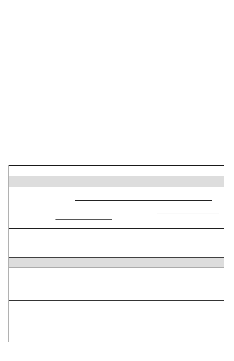
is removed. The following table is a reference for the Setup Instructions below:
ENTER SETUP: Touch pad until lights turn on from 1/8 through 7/8 then release.
E 1/8 1/4 3/8 1/2 5/8 3/4 7/8 F
SENSOR
TYPE
Diagnos
tic mode
10-180
Ohm
240-30
Ohm
Ext < 8”
Int < 12”
Ext >= 8”
Int >= 12”
TANK
SHAPE
Horizontal
Cylinder
Severe
taper
Mild
taper Rectangle
Alarm on
empty
ALARM
TYPE
No
alarm
External
alarm wire
Alarm on
full
ENTER CALIBRATION: Touch pad while middle three lights are flashing.
Empty CALIB-
RATION Full
Power positive to inline fulse to +12-2 VDC
Power ground to battery negative
Sensor power to Red wire(s) on sensor(s)
Tank 1 sensor signal to Blue wire on sensor
Tank 2 sensor signal to Blue wire on sensor
Sensor ground to Black wire(s) on sensor(s)
Alarm power to external device (1 amp max)
Align red wire on
bottom left pin
Red
White
Brown
Black
Blue
Black
Orange

Setup Instructions
1. ENTER SETUP MODE: Press and hold touchpad 1 until lights illuminate from 1/8
through 7/8 after which the lights will turn off indicating the monitor is in setup mode.
Remove your finger from the touchpad. Repeat the setup instructions for tank 2 on
model TM2 using touchpad 2.
2. PARAMETER OPTION SELECTION: The setup mode sequentially advances to
each option for each parameter every 5 seconds and advances to the next
parameter. Tap the touchpad to select a desired option if its light is flashing.
Parameters and options are presented as follows:
a. E light on = SENSOR TYPE parameter is active
i. F light = SCAD sensors: external 8” or longer internal 12” or longer
ii. 7/8 light = SCAD sensors: external less than 8” internal less than 12”
iii. 3/4 light = 240–30 Ohm resistor type float sensor option
iv. 5/8 light = 10-180 Ohm resistor type float sensor option
v. 1/2 light = Diagnostic mode: raw sensor signal voltages. Ignore during
setup. (more information at www.scadtech.com/TMHelp)
b. 1/8 light on = TANK SHAPE parameter is active
i. F light = Rectangular
ii. 7/8 light = Mild taper
iii. 3/4 light = Severe taper (almost triangular shape)
iv. 5/8 light = Horizontal cylinder
c. 1/4 light on = ALARM TYPE parameter is active
i. F light = Alarm on full
ii. E light = Alarm on empty
iii. 1/2 light = No alarm
iv. 3/4 light = External alarm wire energized on alarm condition. This is
selectable if “Alarm on full” or “Alarm on empty” were previously selected.
When the 3/4 light is flashing the wire will not energize on alarm condition.
Tap the touchpad to turn this option on. The 3/4 light will stop flashing.
3. EXIT / RE-ENTER PARAMETER OPTION SELECTION: All lights will turn off
then on again for five seconds. If you want to re-enter the parameter option
selection setup again tap the touchpad. If you do not tap the touchpad the
monitor will proceed to calibration setup.
4. ENTER CALIBRATION SETUP: Next the three top center lights will flash (3/8 1/2
and 5/8) for five seconds. To enter the calibration setup tap the touchpad while
the lights are flashing. To skip the calibration setup do nothing and the monitor
will proceed to normal operation.
5. CALIBRATION: The 1/2 light will stay on to indicate the monitor is in calibration
setup mode. Empty and full calibrations can be set at any time in any order. For
example if the monitor is in normal operating mode and you need to set an empty
or full calibration enter setup mode wait for the parameters and options to
sequence through and then enter calibration mode as described above. Then
calibrate as follows:
a. EMPTY Calibration – With an empty tank while the E light is flashing tap the
touchpad to record the empty level. Do not tap the touchpad if you don’t want
to set the empty calibration.
b. FULL Calibration – With a full tank while the F light is flashing tap the
touchpad to record the full level. Do not tap the touchpad if you don’t want to
set the full calibration.
6. EXIT CALIBRATION SETUP: All lights will turn off after full calibration and the
monitor will return to normal operation.
Operation
When power is applied to the monitor each light will quickly turn on and off as it boots up
then the firmware version will be displayed (See Troubleshooting) after which it will be in
normal operation. The monitor will automatically check for an alarm condition every few
minutes. To see the level of a tank tap the touchpad. If monitor detects and error an error
code will be displayed (see Troubleshooting). For extended level display (approximately 20
minutes) tap the touchpad again within the 3 seconds. This feature is for monitoring the
level while filling or pumping out a tank. The TM2 model will indicate the tank being
monitored by a light next to the number 1 or 2. To exit extended read mode touch the pad.
Alarm Function
If the tank was set to alarm on full the F light will flash if the level is over 7/8. If the tank
was set to alarm on empty the E light will flash if the tank is below 1/8. On model TM2
lights 1 or 2 will indicate which tank is alarming.
External Alarm
During an alarm condition the orange external alarm wire is energized with the battery
voltage level capable of current up to 1 amp which can be used to power an indicator light
audible alarm or relay.
Troubleshooting (Additional help at scadtech.com/TMHelp
Firmware version 3.1 and higher displays fault codes as blinking lights after touching the
pad during normal operation. When the monitor is powered all lights will cycle through
then turn off followed by the firmware version which is determined by counting lights to the
left and right of the 1/2 light which represents the decimal point. For example three lights
to the left of 1/2 and one light to the right is firmware version 3.1.
Blinking Lights Symptom: Possible causes. Action
SENSOR FAULTS
1/2 Sensor signal too low: 1) No sensor connected. 2) No power to
sensor. Put monitor in extended read mode and look for flashing
lights at sensor. If not blinking check wiring and connections. 3) No
signal returning from blue wire on sensor. Check crimp connections
from sensor blue wire. 4) White wires not connected to external
sensor foil strip. 5) Faulty float sensor.
1/2+5/8 Sensor signal too high: 1) Metal object bridging external sensor
foil strips. 2) Black ground wire disconnected or blue signal shorted
to white power wire. 3) Float sensor wiring open or faulty sensor. 4)
Faulty monitor.
CALIBRATION FAULTS (Displayed after sensor faults.)
1/8 (tank 1)
7/8 (tank 2)
Empty calibration too low. See sensor fault too low.
1/8+1/4 (tank 1)
7/8+3/4 (tank 2)
Full calibration too high. See sensor fault too high.
1/8+1/4+3/8
(tank 1)
5/8+3/4+7/8
(tank 2)
Difference between empty and full too small. 1) Full is calibrated
before empty which will be fixed once empty is calibrated. 2)
Calibrated with no signal from sensor. See sensor fault signal too
low. 3) Empty and full calibrated at the same signal level. 4) Short
tank less than 7”. See foil placement section . 5) Full and empty
calibrations are reversed.
▲SCAD Technologies • (336)793-2003 • www.scadtech.com/TMHelp • Firmware 3.3
This manual suits for next models
1
Table of contents


