SCALE-TEC REVA 7900050 User manual

7900050 REVA
JOHN DEERE
750/1560/1590 15FT
GRAIN DRILL
Scale System
Instructions

TABLE OF CONTENTS
7900050 REVA Page 2
Anamosa, Iowa USA
TABLE OF CONTENTS
INTRODUCTION............................................................................................................................................. 3
Charging Battery and Welding .................................................................................................................. 3
SCALE BRACKET AND LOAD CELL MOUNTING INSTALLATION...................................................................... 4
Scale Installation ....................................................................................................................................... 4
JUNCTION BOX MOUNTING.......................................................................................................................... 7
Four Hole Junction Box ............................................................................................................................. 7
INDICATOR MOUNTING ................................................................................................................................ 8
RAM MOUNT............................................................................................................................................. 8
TESTING AND TROUBLE SHOOTING.............................................................................................................. 9
Inaccurate weights? .................................................................................................................................. 9
Erratic weights?......................................................................................................................................... 9
OPERATING THE SCALE ............................................................................................................................... 10
Filling the Central Fill...............................................................................................................................10
Monitoring your seed population...........................................................................................................10
REPAIR PARTS.............................................................................................................................................. 11
LICENSE AGREEMENT.................................................................................................................................. 14

INTRODUCTION
7900050 REVA Page 3
INTRODUCTION
Congratulations on the purchase of your new Digi-Star Grain Drill Scale System. This scale system is
specifically designed to weigh the seed hopper on a 15FT 750/1560/1590 Grain Drill. The scale kit can be
used to record and monitor seed weight going into or out of the seed hopper.
This scale system is covered by the following US patents: 6732667, 7059258 and 7273017. The single-
use license is included with this document (see page 12).
This SAFETY ALERT SYMBOL indicates important safety messages in the manual. When you see
this symbol, be alert to the possibility of PERSONAL INJURY and carefully read the message that follows.
NEVER OPERATE WITHOUT ALL COVERS, SHIELDS AND GUARDS IN PLACE.
KEEPHANDS, FEET AND CLOTHING AWAY FROM MOVING PARTS. FAILURE TO HEED MAY RESULT
INSERIOUS PERSONAL INJURY OR DEATH.
Some covers and guards have been removed for illustrative/photographic purposes only in this manual.
For information on ordering repair parts, refer to Parts Section in this book.
This supersedes all previous published instructions.
IMPORTANT!
Charging Battery and Welding
Disconnect all cables from the weighing indicator before charging the battery or welding on the
machine. If cables are left connected, the weighing indicator and connected load cells could be
damaged.
Important: Do not weld near indicator, load cells or cables; remove from area to be welded. Place
ground close to area to be welded to prevent current from passing through electronic parts.

Scale Bracket and Load Cell Mounting
7900050 REVA Page 4
SCALE BRACKET AND LOAD CELL MOUNTING INSTALLATION
Scale Installation
1. On the right side, as you are facing forward looking at the tractor, loosen the four 7/16
bolts that hold the seed bin to the frame.
2. On the left side, remove the 7/16 bolts that hold the seed bin to the frame.
3. On the inner frame on the left side (that runs under the seed bin) place a jack between the
frame and seed bin. Lift the seed bin up about 2-1/2” on the left side.
t is recommended the hopper be supported by two methods when attaching the load cells
and brackets. In addition to lifting the hopper with a chain or nylon strap, the hopper should
be supported in the middle with a hydraulic jack or stands.
4. Install the middle bracket under the seed bin. Reuse 7/16 hopper bolts (do not tighten
bolts yet).
The hopper can be lifted by
wrapping a nylon strap or chain
around the hopper end (left side of
hopper).
Important. The lifting chains, bucket attachments, loader/skid steer or winch must be
capable of lifting and controlling 1000 lbs.
Location of secondary hopper
support using the middle frame and
a hydraulic jack. The jack must
support the body, not the fluted
wheel drive.

Scale Bracket and Load Cell Mounting
7900050 REVA Page 5
5. Install the front and back weigh-bar with the 2-1/4” x 3/8” pins (make sure the arrow
sticker on the end of the weigh-bar is pointing up). Weigh-bars with 16 ft cords to the rear,
and 11 ft cords 4 ft to the front (long cords go on back of drill, short cords go on front of
drill).
6. Let the seed bin down to about 1” and slide the rear bracket on. Use the 5/8” x 8” bolts in
the front 2 holes. On the rear bracket there is a 2” box tubing with a 1/2” hole. Use the 2-
1/2” x 3/8” clevis pins with a washer on each side; make sure the clevis pin is in the center
of the hole. (Note: the rear step grip is installed between the rear bracket and the step
bracket already on the grain drill. Do not tighten the bolts.)
7. Install the front bracket with new 5/8 x 8” bolts. Use the 2-1/2” x 3/8” clevis pin to go
through weigh bar and bracket. The clevis pin should be in the center of the 1/2” hole.
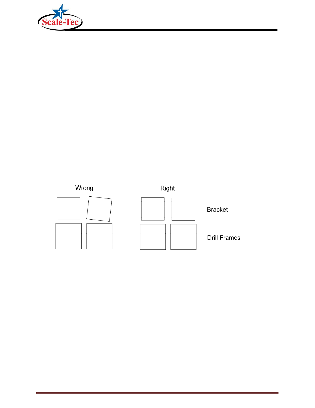
8. Make sure the middle, front and rear brackets are straight with each other. Tighten the
middle bracket first, then the front and back brackets.
9. Remove the bolts on the right side that hold the seed bin to the frame. Remove the drive
chain and clutch drive arm (1” x 1/4” flat steel) attached to the seed hopper and clutch
drive.
10. Repeat steps 3 to 8 on the right side of the drill.
11. When both sides are complete, all the brackets should stand straight.
12. Lengthen the drive chain with chain links provided. Do not over tighten chain. Leave the
chain loose enough so it is not pulling down on the seed bin.
13. Attach the new clutch arm. Drill a hole so the clutch is disengaged when the drill is up, and
engaged when the drill is down. The length extended on the clutch arm is approximately
1”, the same distance the seed bin was raised from the scale system. NOTE: Make sure
the clutch arm is mounted on the back side of the clutch.

Scale Bracket and Load Cell Mounting
7900050 REVA Page 6
John Deere Grain Drill Scale Kit

JUNCTION BOX MOUNTING
7900050 REVA Page 7
JUNCTION BOX MOUNTING
Four Hole Junction Box
The junction box is water resistant, not water-proof. It should be mounted to avoid submersion during
wet weather and to avoid physical abuse. The junction box can be mounted on the front or rear of the
drill, planter or seeder. All load cell cables must reach the J-Box. Install by removing the double sided
tape backing and apply to cleaned surface.
Connect Load Cell and Junction Box Cable
1. Route front and rear load cell cables of to J-box location.
Make sure they are not bound or pinched. Cable tie
(Customer provided) load cell cables in place.
2. Insert load cell and J-box cables through each of the
water-tight strain-reliefs.
3. Remove each terminal block from the J-box.
4. Connect wires of the same color to the same terminal
block as shown above. See instructions below.
5. Install terminal block into the J-box as shown (location
not important).
6. Tighten nuts on the water-tight strain-reliefs.
7. Assure that gasket is properly installed in the cover.
8. Attach cover using 4 screws (provided).
Installing Wires into Terminal Block
1. Open levers 90º to locked position.
2. Insert individual wires into terminal.
3. Close lever.
4. Tug wire to assure solid connection.
Note: Wire strip length is 7/16” (11mm).
Fig.

Indicator Mounting
7900050 REVA Page 8
INDICATOR MOUNTING
RAM MOUNT
The scale indicator can be mounted in the tractor cab or on the drill with swivel mounting pack
(406081). Two cables must be connected to the indicator bottom panel, J-Box and power cables.
Refer to Indicator Manual D3831-US for details of indicator mounting options and connection of
power cord.
INDICATOR MOUNTINGS
PLANTER MOUNTING TRACTOR CAB MOUNTING
1. Bolt the readout in the cab with the bracket, or mount the bracket in the front of the lift
cylinder.
2. Install power cord to a 12-volt negative ground battery.
3. Route J-box cable to indicator and install to indicator bottom panel.
4. Program indicator with set-up #145015 and calibration #14000 (see Indicator Manual)
Power Connection:
The power cable should be connected directly to a vehicle battery or regulated power supply. The scale
end of the power cable is attached to the J901 connector located on the bottom panel of the indicator.
Connect the RED wire from the power cable to +12 VDC and the BLACK wire to GROUND. The indicator is
fused internally at 4 amps.
Power Cable Connections:
Wire Color
Wire Function
Red
Battery (+12 VDC)
Black
GROUND

Testing and Trouble Shooting
7900050 REVA Page 9
TESTING AND TROUBLE SHOOTING
IMPROTANT All bars need to weigh accurately before it will be beneficial to recalibrate your
indicator
Inaccurate weights?
1) Measure the same person, or a 200 pound bag of seed, on each of the weigh bars.
If one weighs negative, turn that weigh bar over. (An upside down bar will weigh negative.)
If one side is weighing 20% light, check for an obstruction. Is anything binding or any metal
rubbing?
Could be a faulty weigh bar
If they are all even weights, but are weighing light or heavy, you need to adjust the calibration.
If your scale is more than 5% off, call us for help, as your scale may have had the wrong
calibration number put in it from the factory. 1-888-962-2344.
The hopper being weighed needs to be at least ¾ full for us to adjust calibration.
Check operator’s manual or give us a call at 1-888-962-2344.
Erratic weights?
The following process needs to occur in an effort to eliminate one part at a time in an effort to find the
problem! When you reconnect the faulty part you will have erratic readings again.
1) Disconnect the junction box cord from the indicator marked “load cells”. The indicator should
stabilize after 45 seconds. Try to zero out the indicator. IF the indicator won’t zero out, the indicator is
the problem.
IF it will zero out:
2) Connect the junction box back to the indicator. And then disconnect all of the load cells from the
junction box.
3) Zero out the indicator. IF the indicator won’t zero out the problem is the junction box or the junction
box cable.
IF it will zero out:
4) Reconnect the load cells ONE AT A TIME, zeroing out the indicator each time. When you reconnect
the faulty load cell, you will have erratic readings again.

Operating the Scale
7900050 REVA Page 10
OPERATING THE SCALE
Filling the Central Fill
NOTE: The example given uses 2000 lbs of seed evenly filled in both hoppers. There is 25 lbs of seed left
from the last fill.
1. Push the "Start" button. The screen will show zero, and the arrow is now pointing to "Net" on the
screen. This is a temporary zero point to start loading the planter with seed. You will now fill 1000lbs of
seed into the left hopper.
2. Push the "Stop" button, the readout will display 1025 lbs of seed inventory.
3. Push the "Start button again. The screen will say zero again. Load another 1000 lbs of seed into the
right side.
4. Now push "Stop" and the screen will read 2025 lbs of seed. As planting occurs the weight displayed
will decrease.
Monitoring your seed population
NOTE: This procedure assumes all hoppers have been filled to some degree and you are ready to plant.
1. Prior planting stop the implement in relatively level location.
2. Ensure the planter is raised to the full up position.
3. Let the scale stabilize, after stabilization, press the "start" button.
4. Lower the planter and begin planting seed.
5. Plant 5-10 acres and come to a stop in a relatively level location.
6. Raise the planter to the full up position.
7. Let the scale stabilize, after stabilization note the weight displayed on the indicator. The weight
displayed is the weight that was planted over the 5-10 acre area.
8. To determine your seed population follow the formula given:
Acres / Weight = Population

Repair Parts
7900050 REVA Page 11
REPAIR PARTS

Repair Parts
7900050 REVA Page 12
KEY
QTY.
PART NO.
DESCRIPTION
1
1
405763
Weld –Front Brkt RH (JD750-15’)
2
1
405763
Weld –Front Brkt LH (JD750-15’)
3
1
405761
Weld –Rear Brkt RH (JD750-15’)
4
1
405760
Weld –Rear Brkt LH (JD750-15’)
5
2
405764
Weld –Middle Brkt (JD750-15’)
6
4
405854
SCR –1/2-13 x 2-1/4 HHCS ZP Grd 5
7
8
405863
SCR –5/8-11 x 8-1/2 HHCS ZP Grd 5
8
8
171610
Wash - 3/8 Flat Narrow ZP
9
4
405053
Wash –1/2 Flat Wide ZP
10
16
405858
Wash –5/8 Flat Wide ZP
11
4
406085
Nut –1/2-13 Ser Flange ZP
12
8
406070
Nut –5/8-11 Top-Lock Flange ZP
13
8
405859
Pin –Cotter 5/32 x 1.5 ZP
14
4
405861
Pin –Clevis 3/8 x 2.5 ZP
15
4
405860
Pin –Clevis 3/8 x 2.25 ZP
16
3
405862
Link –Offset #40
17
1
405838
Bar –26.125” Clutch (JD1590750)
18
2
400400
Cell –1.5 DB –16FT
19
2
400373
Cell –1.5 DB –11FT
20
1
406232
J-Box Lever Nut 4PT (Planter)
21
1
141837
Cable –30FT J-Box
22
1
405072
Cable –Power 6FT 2-Wire
23
1
405512
GT400 Indicator

Repair Parts
7900050 REVA Page 13
406081
406385
406081
KEY
QTY.
PART NO.
DESCRIPTION
1
1
403980
Brkt –Robo Mtg
2
2
406086
Brkt –Swivel Cast (JD H161618)
3
2
406087
Gasket –1.813OD x 1.218 ID x .313 WID
4
2
400036
Scr –1/4-20 x 3/4 HHCS ZP
5
2
400038
Washer –Lock 1/4 ZP
6
2
400035
Nut –1/4-20 ZP
7
2
405989
Scr –3/8-16 x 3.0 HHCS ZP Grd 5
8
2
404292
Nut –3/8-16 Nyloc ZP
9
2
405612
GT400 Indicator (Not included in kit 406081)
406385
KEY
QTY.
PART NO.
DESCRIPTION
1
1
404230
Ram Suction Cup with Twist Lock
2
2
403180
Assembly –1” Ram Mount
3
2
403779
Scr - #10 x 5/8 PHSTS 48-2 Blk ZP

License Agreement
7900050 REVA Page 14
LICENSE AGREEMENT
IMPORTANT NOTICE: Acceptance and use of the enclosed
electronic scale products (hereinafter referred to as
“Purchased Product”) constitutes your agreement to the
following terms and conditions. Please carefully read the
following terms and conditions before using or reselling the
Purchased Product.
1. Limited License. Digi-Star, LLC, a Wisconsin limited
liability company (“Owner”) is the owner of the following U.S.
Patents related to grain drills: 6,732,667, 7,059,258,
7,273,017, 7,357,087, 7,448,335, 7,523,710 and any other
patents which result from continuation applications thereof
(“Patents”). Owner hereby grants to the customer
(“Customer”) a non-exclusive, non-transferable, revocable,
limited license to use the technology described in the
Patents to use the Purchased Product to assemble a seed
planter product covered by the Patents (“Licensed Product”),
and to sell and offer for sale one (1) unit of the Licensed
Product in accordance with the terms and conditions set
forth herein. Alternatively, Customer may resell the
Purchased Product to another entity for the purpose of that
entity assembling one (1) unit of a Licensed Product under a
permitted sublicense from the Customer with the same terms
as this Agreement. If Customer would like to assemble, use,
sell or offer for sale more than one (1) Licensed Product,
or resell more than one (1) Purchased Product, Customer
understands and agrees that it must purchase another
Purchased Product from Owner or acquire a separate
license by requesting and purchasing another unit
of the same SKU number that resulted in this purchase.
2. Acceptance of Terms and Conditions. Customer warrants
that it has the authority to enter into this binding agreement.
If Customer does not accept the terms and conditions,
Customer shall not use the Purchased Product. Customer
understands and agrees that if it uses the Purchased
Product as permitted herein, it will be deemed to have
accepted these terms and conditions and they shall become
a binding agreement.
3. Limitations on Use. Customer agrees that it will use the
Licensed Product only as expressly authorized in this
Agreement, and that any use not expressly authorized in this
Agreement is prohibited. Customer agrees that it will not: (i)
loan, rent, lease, assign, sublicense, distribute
or otherwise transfer its rights under this Agreement to a
third party, other than to resell the Purchased Product to
another entity for the purpose of that entity assembling one
unit of a Licensed Product; (ii) copy or reproduce the
Licensed Product; or (iii) grant any sublicenses
other than to an end user of the Licensed Product, or to
another entity for the purpose of that entity assembling one
unit of a Licensed Product.
Customer agrees to use reasonable efforts to prevent any
unauthorized use or copying of the Licensed Product and will
notify Owner immediately upon learning of any such
unauthorized use or copying. Customer’s obligations under
this section shall survive any termination of this Agreement
or the license granted hereunder. Any unauthorized
use of the Licensed Product will result in, among other
things, the immediate termination of this license.
4. Ownership of Proprietary Rights. Customer acknowledges
that the Licensed Product is covered intellectual and/or
proprietary rights, and that all such intellectual and
proprietary rights are owned by Owner.
Customer hereby acknowledges that it has no rights in the
foregoing except as expressly granted herein.
5. NO WARRANTY. Customer agrees to fully test and
evaluate
the Purchased Product and Customer acknowledges and
agrees that Owner will not assume any product liability or
any other liability for the Purchased Product or the Licensed
Product. The Purchased Product is furnished to Customer
“AS IS.” Except as otherwise provided by separate
documentation, OWNER MAKES NO WARRANTIES,
EITHER EXPRESS OR IMPLIED, WITH RESPECT TO THE
PURCHASED PRODUCT. Customer agrees that Owner
shall have no liability resulting from Customer’s use of the
Purchased Product for any indirect damages including
consequential, incidental or special damages for loss of
profit, good will or otherwise. Customer shall indemnify and
hold Owner harmless from any and all losses, expenses,
damages, costs or expenses of any kind, including but not
limited to reasonable attorneys’ fees, incurred by Owner
resulting from Customer’s use of the Purchased Product. NO
ORAL OR WRITTEN STATEMENTS MADE BY
OWNER OR ITS EMPLOYEES INCLUDING BUT NOT
LIMITED TO STATEMENTS REGARDING CAPACITY,
SUITABILITY FOR USE, OR PERFORMANCE OF THE
PURCHASED PRODUCT SHALL BE DEEMED A
WARRANTY OR REPRESENTATION BY OWNER FOR
ANY PURPOSE NOR GIVE RISE TO ANY LIABILITY OR
OBLIGATION OF OWNER.
6. Remedies for Violations. Owner reserves the right to seek
all remedies available at law and in equity for violations of
this Agreement, including but not limited to the right to
recover the Licensed Product.
7. Fees. In consideration for the rights granted under this
Agreement, Customer has paid a license fee that was
included in the amount invoiced to the Customer for the sale
of the Purchased Product.
8. Entire Agreement. Except as expressly stated herein to
the contrary, this Agreement constitutes the entire
agreement between the parties regarding the subject matter
hereof, and no verbal or written prior statements or
representations of any sort made by any party shall be
effective or valid for any purpose whatsoever. This
Agreement may be amended only upon the mutual consent
of all parties in writing.
9. Severability. If any provision of this Agreement shall be
held to be invalid, illegal or unenforceable, the validity,
legality and enforceability of the remaining provisions shall
not in any way be affected or impaired thereby. The failure of
any party to enforce any provision of this Agreement shall
not be considered a waiver thereof, nor shall such failure
prevent the future enforcement of any such provision.
10. Governing Law. This Agreement and the relationship
between the parties shall be governed in all respects by the
laws of the State of Wisconsin and the United States of
America. The parties consent to the jurisdiction and venue of
the Wisconsin and United States courts located in Wisconsin
for resolution of any dispute under to this Agreement.
Use or sale of the Licensed Product or of Purchased Product shall bind Customer to all terms
and conditions herein without the necessity of signatures on this Agreement.
This manual suits for next models
4
Table of contents