Scheibe Aircraft SF 25 C-FALKE Technical specifications

........
·-·--..--~-
·-·--=---
SCHEIBE
AIRCRAFT
GMBH
D - 73540 Heubach,
Am
Flugplatz 5
Tel.:
(0)7173/184
286 Fax:
(0)7173/185
587
e-ma
il:
info@scheibe-aircraft.de
F L I G H T M A N U A L and Maintenance Manual
Serial no:
SF 25 C - F A L K E
motorglider
ROTAX 912 A
()
or
ROTAX 912 5 (2)
maximum all-up weight 680
kg
(604
kg
•11ith
Folding
Wings)
610
kg
(634
kg
with
Folding
Wings)
650
kg
(674
kg
with
Folding
Wings)
690
kg
(714
kg
with
Folding
Wings)
MARCH 1997
Registration no:
44662
G-FLKS .,
Owner: London Gliding Club
~
I/
'
//
f
1£;/f"
/i.::
European Aviation Safety
Age
r
~,
PeulHATTCN
Edition March 1997 Rev.
9,
10.04.2014 Project
CeT1ffiCOlioo
Manager
Pages 1-30
of
this Flight manual are EASA approved
EASA.A.C.10048806
This manual is to be keet
on
board
at
all times.
' '
l
I
i
I
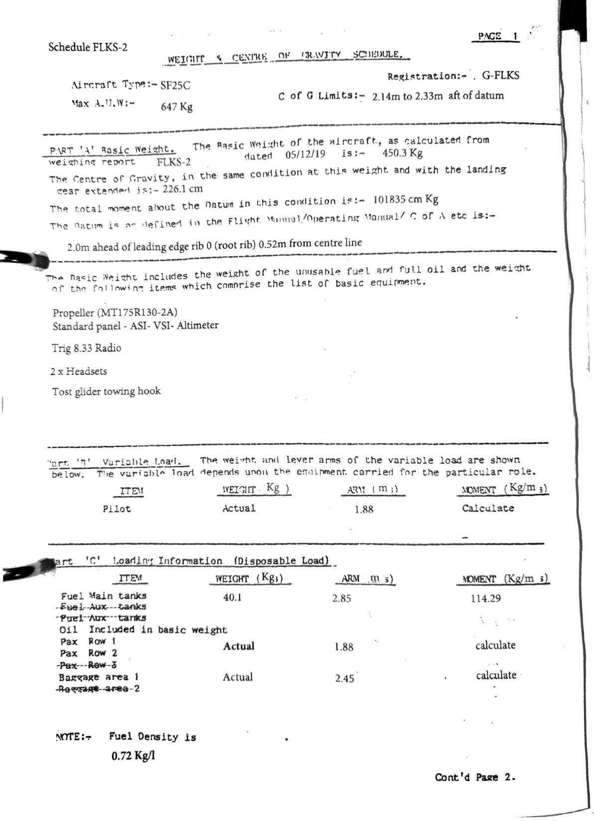
Schedule
FLKS-2
P
.
t\C~
WElC~trr
\
C~~·mi.;
<W
r;n,\VJ'rV SOll!l>Ul.E•
...
_.
-
--
----
----
--
:\i
rr.rart
iy~
:-
SF25C
Re.(i~tration:-
·.
G-FLKS
'fax A. !J.
\V:
-C
of
0
Llmlts
:-
2.14m to 2.33m aft
of
datum
64
7
Kg
~---------~--------------
---1
·~~
~------------------
P:\PT 'A'
~osic
\~ei
.
t?ht.
ThP.
R~!=.ic
WP.i
:.t
ht
or
the
1'\lrcrnft
.,
as
calculaterl
from
i:1ute<1
05/12/19
is:-
450.3
Kg
wei~
hiM:
report
FLKS
-2
ThP.
r.entre
of
r.ru
v
ity,
in
the
· same
con<\ition
r\t
t.hi1=
wel~ht.
and
with
the
landing
t!~ar
e'<t~l"trlP•\
j
~
~
-226.l
cm
ThP.
to
tal
"'IOment
ahout
the
naturn
in
this
condition
l!=
:-
101835
cm
Kg
The
1
atn
ni
ic: ;'\ r
<I
P.finer!
in
t.hP.
Flit{ht
.
'':1111
.
1u1
.
lnperntin~
\l<J111Jl-\l
/
~
of
,\
etc
.is-:-
2.0m ahead
ofleading
edge rib 0 (root rib) 0.52m from centre line
---------·---·---
.~~~--~-----------------------·--~-
Tl°'"' n::i.c:ic
;
v~ictlt.
includes
the
wei~ht
of
the
unusaol~ fu~l
::irY1
ful.l
oil
and
the
wei$t
l')f
t
~
ft'll
l
nw;
n~
itP.m.c:
which
cnmnrise
the
list
of
basic
e
Q"ui
pcnP.nt.
Propeller (
MTl
75R130-2A)
Standard panel -ASI- VSI- Altimeter
Tri
g 8.33 Radio
2 x Headsets
Tost glider towing
hook
·~
rt:~
Vuri::ihl~
t.o_a•I.
Th~
wei<rht.
and
lP.ver
arms
of
the
variable
load
are
shown
bP.
low. T
l1
e
vari
~hl"
1
naii
rlepenrls
UM1\
th~
e
!i
1,
li
fl1'11ent.
carr
1·
e'.~
fo
..
the
1 •
particu
l
ar
role.
lVEI'.;!IT
.
Kg
)
Pilot
Actual
rt
t.oarlin·r
Infonnatlon
(Dis
sable
Load)
ITE\f
WEIGHT
(Kg;)
Fuel
~a.in
tanks
-
$"1&1
--
Aux.-
--
.t.anks
-
1"tre'1
--
Aax---
tal"lb
40.1
Oil
Included
in
basic
weight
Pax
Jlow
I
Pax
Row
2 Actual
-Pax---Aew-d
BaJ?'{a~
area
1
-R-e~..a.r-ea
-
2
~OTE:~
Fuel Density
is
0.72
Kg/I
Actual
A.T'l\1
( m ;)
1.88
2.
85
1.88
2.45
~tJMENT
(
Kg/m
:;
)
Calculate
~f)MENI'
(Kg/m
;)
114.29
calculate
calculate ·
Cont'd
Pue
2.
'
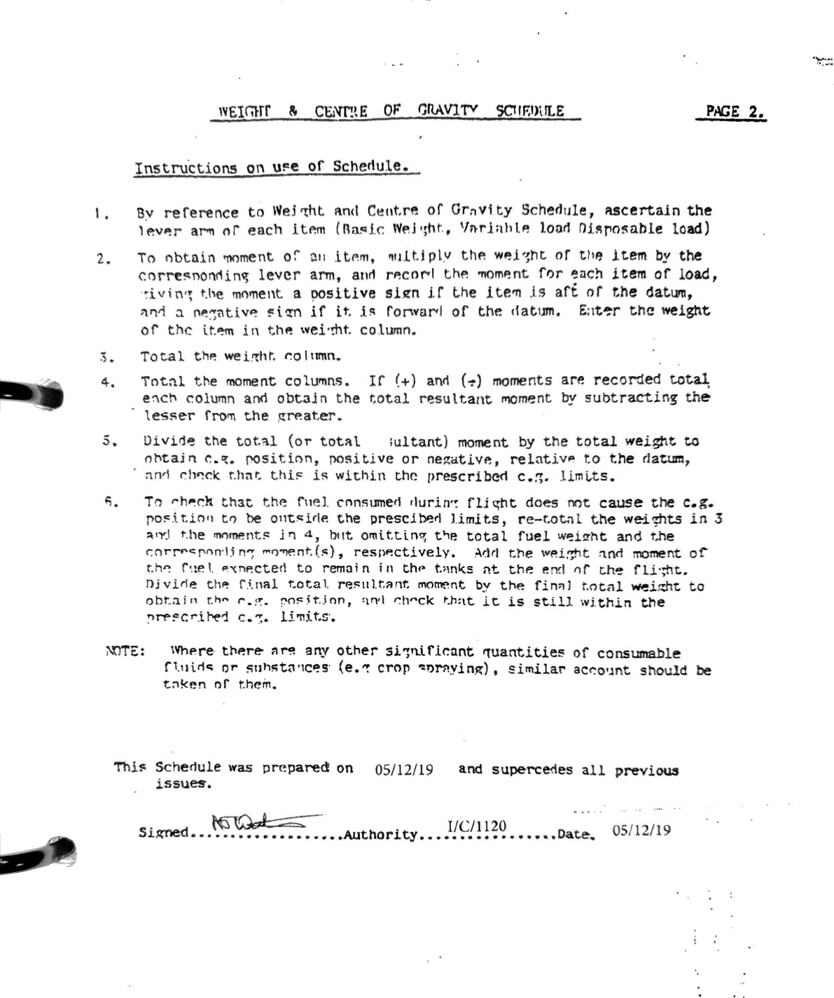
wE1rnrr
~
CENT!~E
OF
CRAVl'f'V
SCtlF,1)\ILE
PAGE
2.
Instru
'
ctions
on
ui=e
of
Schedule.
1•
By
reference
to
We5
rcht
A.n<I
Cent.rft
of
Grnvity
Schedule,
ucert.aln
the
l~v~r
ar-n
nr
each
itP.m
(Rac:ik
\'t'~J
c;ht
.
,
Vn-rl:thlP.
loot!
rHllltio~ahle
load)
2.
To
obtain
mment
or'
a11
.itP.rn, 1
u11t.i
pl
.v thP.
WP.i
-~nt
of
t!IP,
item
by
t~
cnrre~nonrlin~
lever
arm,
arn1
rP.cor<I
th~
'YIOmP.nt
fl)r
l!!nch
item
or
load,
·
~iv
i
tv~
t.
he
moment a
!)OSiti
ve
slsm
H
the
i
te'TI
J.s
aft
or
the
datum,
:vl'i
:i
l'\P.~ntiv"?
~i~n
if
it
.
.i~
ro~varl
of
the
cfatum.
Eat~r
t.hc
weight
or
the
lt.~
in
thP. wei·mt.
column.
:;.
Total
thP.
wei.~ht.
~olnmn.
4,
iot~l
the
moment
colu~ns.
If
(+)
anri
(~)
moments are recorded
total:
e:"lcl°'
column and
obtaln
the
total
resultant
l"IOment
by
subtracting
th
e
tes~er
fro~
the
~~ater.
5.
Divid~
the
total
(or
total
iultant)
moment
by
the
total
weight
to
nl°'tajn
~-~·
f'OSition,
positive
or
ne~ativP.,
relat
iv
P
to
the
rJa~um,
nn'\
~h~r.k
r.har:
thii::
iR
within
the
prescribeci
c.:;.
limi.,ts.
~-
Tn
rh~dl
that
thP.
rnel.
cnn!'iumert
rlurin'~
fli
~ht
does
not
cause
the
e.g.
po!=
.
i.tio11
trJ be 011tc:;i<IP.
the
presci~rl
limits,
re-r.ot
;}l
the
we-ic;hts
in
3
~
·
YJ
t.
he
rMrnent~
j
l'l
d.,
b11t ornittin-;r,
t'ie
total
fuel
w~izht
and
the
<:nr!f'c:f'nn
·
l.in~
""fJ~nt
.
(~),
respP.ctlvely,
Adrl
ttie
wP.i~t
:in<l
moment
of'"
th~
r•.te
I.
P"(nP.ctecl
to
rem:ii
n
in
th(>
t~ml<s
nt.
thP.
en~!
nf
t.h'!
fli·;ht.
njvirle
th~
f .
i.nal
total
rP.~111.t.~nt
morrent
by
the
fin;il
t.ntnl
~i~t.
to
obt
.
:iin
t.h"'
r.rr:.
f'O~~t
.
.inn,
<\ri•I
~h,,ck
t-.h:\t
it.
is
still
within
the
'.'l~~cr.it-e1
C.";.
li'l'!HS.
;\tlTE: WhP.re· tl"IP.re-
:ir~
any
other
:si-;rtlfkant
'lUantitie5
of
consumable
fl.u\rlc:;
or
s11h!itn
·1
c~s
·
(e.~
crop
-:oNwin~),
similar
ac~o·.mt
should
be
t~!<en
or
t.hein.
Thi~
Scher1ule was prc!paredi
on
05/12/19 and
superc~es
all
previous
iSSUe!t.
.
~~
-
. l/C/1120 -·- . 05/12/19
Si,ctned
•••••••••••••••••••
Authority
•••••••••••••••
,.Date.
.
.,..._
.
......

FLUGHANDBUCH SF 25 C (Beiblatt: Austohrung)
This SF 25 C
Equipmen
t:
1.
E
ng
ine:
2. Propeller:
Se
ri
al N
°:
Ca
ll
Sign:
ROTAX
91
2 A 2)
.
:i'.·
ROTAX
91
2 S(2)
''
44662
G-FLKS
ROTAX 912 A 3)
x
ROTAX
912 S
3)
has following
ROTAX
912
A(4
ROTAX
912 S 4
Only
for ROTAX
91
2 A(1) , A(2)
or
A(4)
HO
11
AHM
-1
65130
Onl
y
for
ROTAX
91
2 A(1) , A(2) or A(4)
MT
165 R 130-
2A
Only
for ROTAX 912
$(2
) or S(4) MT 170 R 135-
2A
~
n1v
·
f~
fttta
'i·'f
a~l!8
tf
.
JW
'
d
s
$
:
~s
o
/"69"0~~
\
~
~?4•
1t:
~
;~W~t~;
MT 175 R 130- 2A x
O
nly
for ROTAX 912 A(2) and A(4) or 912
$(2)
and
$(4)
MTV
1A/
175-
05
~1
ftit®'tfx
.
'
:fa'k
e
~
'&W'ffi
at:l
~l3
·
q
7
t(o
t
(~t);(
.}
rco1
;~*~"5\1~<'~i-:'21i
.:z~f
~·:;
{0i'J/'.
3. Spacer for
fi
xed pitch Propeller: SF 653 C- 71- S1.4 E1
MT A 548
Limbach 20
1.
032. 070
4. Prope
ll
erdome for fixed pitch Propeller: .
MT
B-
030
(ALU)
MT
B-
030/1 {GFK)
Hoffmann- Prope
ll
e
r:
VP
30-63
Toqether with VP
30-
64
5.
Take-off mass:
650
k *
490 k
7. Version
of
landing gear: Sinqle Main wheel (fixed) 8.00x 4
Sinqle Main wheel (spruno) 6.00 x 6
Two wheel
ma
in
landing gear 5.00x 5
with tailwheel 21
0x
65
Two wheel main landing gear 5.00x 5
with nose wheel 330x 130
360°- tailwhe
el
210x
65
8. Wings: of ailerions
9. Fuel capacity: 441
551
80 I
Fixed Aerotow device with TOST- Noselaunching hook
x
x
x
x
x
C:\MSOFFICE\WINWORD\TECHN\FHBWHB25\BEIBL
_25.D
OC
10
.
02.2
0
15
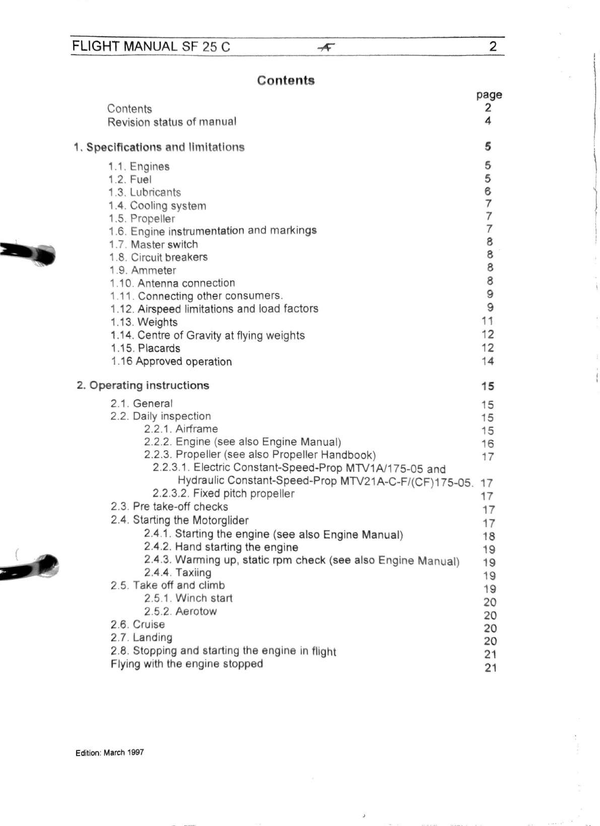
FLIGHT MANUAL SF 25 C
Contents
Revision status
of
manual
1.
Speciflcati n
nd
limitation
1.1. Engine
1.2. Fuel
1.
3.
Lubricants
1.4. Cooling system
1.
5.
Propeller
C n n
1.
6.
Engine instrumentation and
markings
1.7. Master switch
1.8. Circuit breakers
1.9. Ammeter
1.10. Antenna connection
1.11. Connecting other consumers.
1.12. Airspeed limitations and load factors
1.13. Weights
1.14. Centre
of
Gravity at flying weights
1.15. Placards
1.16 Approved operation
2.
Operating
instructions
2.1. General
2.
2.
Daily
in
spection
2.2.
1.
Airframe
2.2.2. Engine (see also Engine Manual)
2.2.3. Propeller (see also Propeller Handbook)
2.2.3.1. Electric Constant-Speed-Prop
MTV1A/175-05
and
Hydraulic Constant-Speed-Prop
MTV21A-C-F
/(CF)175-05.
2.2.3.2. Fixed pitch propeller
2.3. Pre take-off checks
2.4.
St
arting the Motorglider
2.4
.1
. Starting the engine (see also Engine
Manua
l)
2.4.2. Hand starting the engine
2.4.
3.
Warming up, static rpm
check
(see also
Engine
Manual)
2.4.4. Taxiing
2.5. Take off and climb
2.5.1. Winch start
2.5.2. Aerotow
2.
6.
Cruise
2.7. Landing
2.
8.
Stopping and starting the engine in flight
Flying with the engine stopped
Edition
:
March
1997
2 J
~
' i
"
page
2
4
5 '
'
\
5
5 I
6 1
7
7 I
7 I
8 I
!
8
8
8
9
9
11
12
12
14
15
15
15
15
16
17
17
17
17
17
18
19
19
19
19
20
20
20
20
21
21
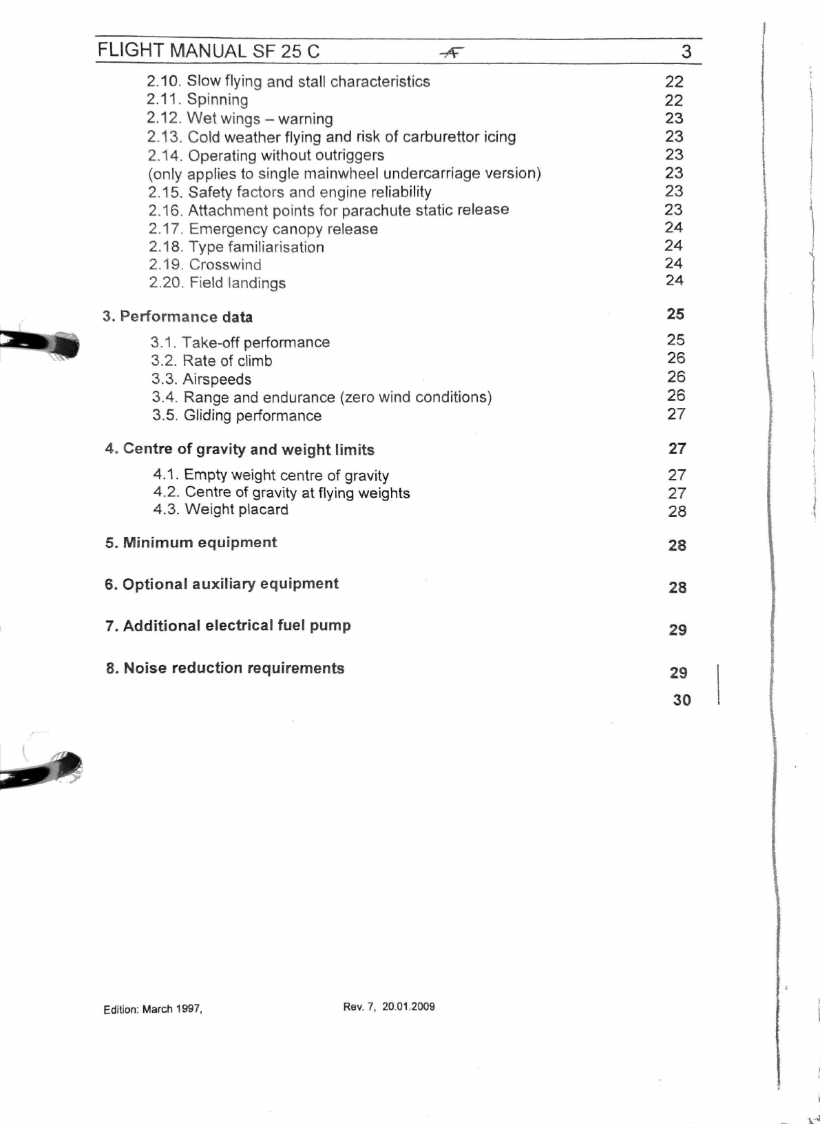
FLIGHT MANUAL SF 25 C
2.10. Slow flying and stall characteristics
2.11. Spinning
2.12.
Wet
wings -warning
2.13. Cold weather flying and risk of carburettor icing
2.14. Operating without outriggers
(only applies
to
single mainwheel undercarriage version)
2.15. Safety factors and engine reliability
2.16. Attachment points for parachute static release
2.
17
. Emergency canopy
re
lease
2.18. Type familiarisation
2.19. Crosswind
2.20. Field landings
3. Performance data
3.1 . Take-off performance
3.
2.
Rate of climb
3.3. Airspeeds
3.4. Range
and
endurance (zero wind conditions)
3.5. Gliding performance
4. Centre of gravity and weight limits
4.1 . Empty weight centre of gravity
4.2. Centre of gravity at flying wei
gh
ts
4.3. Weight placard
5. Minimum equipment
6. Optional auxiliary equipment
7. Additional electrical fuel pump
8. Noise reduction requirements
Edition: March 1997,
Rev.
7,
20.01.2009
3
22
22
23
23
23
23
23
23
24
24
24
24
25
25
26
26
1
26
27
l
27
I
27
l
27
28
,,
28
28
29
29
30
FLIGHT
MANUAL
SF
25 C 4
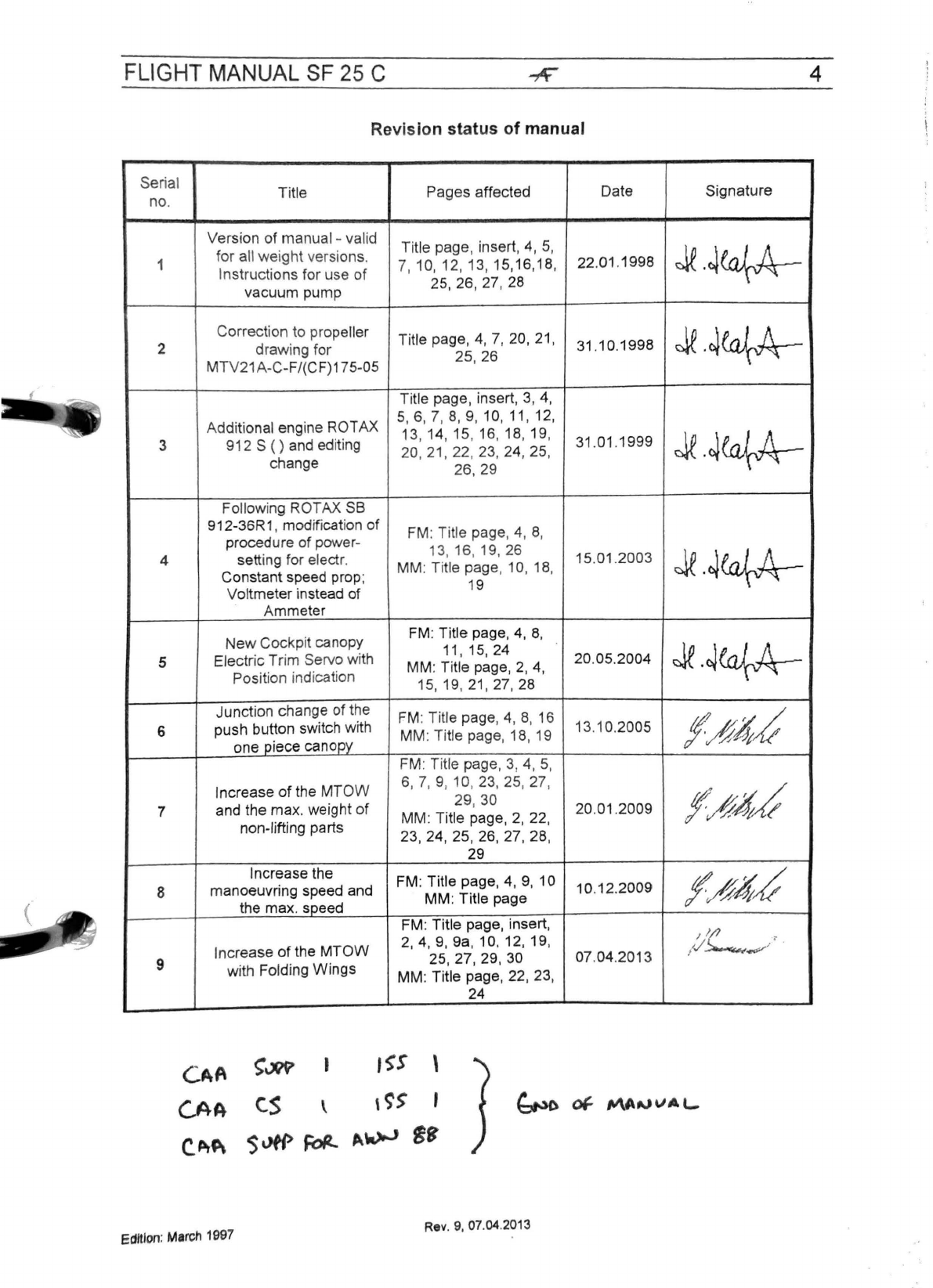
Revision status of manual
Serial Title Pages affected Date Signature
no.
Version
of
manual -valid Title page, insert, 4, 5,
Je.~ea{-A--
1 for all
weight
versions.
7,
10, 12, 13, 15,16,18, 22.
01
.1998
In
st
ructions for use
of
25, 26, 27, 28
vacuum pump
Correction to propeller Title page,
4,
7, 20,
21
, 31.10.1998
Je.~ea{-A--
2
draw
ing for 25, 26
MTV21A
-C-F/(CF)175-05
Title page, insert, 3, 4,
Add
itional engine ROTAX
5,
6, 7,
8,
9, 10,
11
, 12,
13, 14, 15, 16, 18, 19,
31
.
01
.1999
Je.~ea{-A--
3 912 S
()
and editing 20,
21
, 22, 23,
24,25,
change 26, 29
Following ROTAX SB
912-36R1, modification
of
FM: Title page, 4, 8,
procedure
of
power- 13, 16, 19, 26 15.
01
.2003
Je.~ea{-A--
4 setting for electr. MM: Title page, 10, 18,
Constant speed prop; 19
Voltmeter instead of
Ammeter
New
Cockpit canopy FM: Title page,
4,
8,
Je.~ea{-A--
11, 15, 24 20.05.2004
5 Electric Trim Servo with MM: Title page,
2,
4,
Position indication 15, 19,
21
, 27, 28
Junction change
of
the FM: Title page, 4, 8, 16 13.10.2005
f~~~
6 push button switch with MM: Title page, 18, 19
one piece canoov FM: Title page, 3, 4, 5,
Increase
of
the
MTOW
6, 7, 9, 10, 23, 25, 27,
f~%~
29, 30 20.
01
.2009
7 and the
max
. weight
of
MM: Title page,
2,
22,
non-lifting parts
23,24,
25, 26,
27,28,
29
Increase the FM: Title page, 4, 9, 1O
10
.12.2009
f/f4~
8 manoeuvring speed and MM: Title page
the max. speed FM: Title page, insert,
'L
,
Incr
ease
of
the
MTOW
2,
4,
9,
9a, 10, 12, 19, 07.04.2013
;/
._-
' .
25,
27,29,
30
9 with Folding
Wings
MM: Title page, 22, 23,
24
~vw
1
1~s
\
c.s
\
'~>
'
$~
~
~_,..,
~'
Edition
:
Mmrch
1997
Rev
.
9,
07
.
04.2013
FLIGHT MANUAL SF 25 C 5
The pilot
is
responsible for ensuring that the aircraft is operated
in
accordance with the
Flight Manual.
The SF25C is authorised to carry a maximum of two adults.
The seating is side by side: the pilot sits
on
the port side.
The SF25C
is
ideal for training. For training purposes the instructor (P1) may sit on either
side. All regulations must be observed.
The starboard control column may
be
removed for passenger flying.
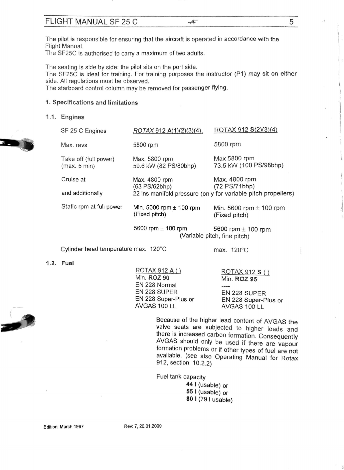
1.
Specifications
and limitations
1.1. Engines
SF 25 C Engines
Max. revs
Take off (full power)
(max. 5 min)
Cruise at
and
additionally
Static rpm at full power
ROTAX912
A(1)(2)(3)(4), ROTAX 912 5(2)(3)(4)
5800 rpm 5800 rpm
Max.
5800 rpm Max 5800 rpm
59.6 kW (82 PS/80bhp) 73.5
kW
(100 PS/98bhp)
Max.
4800
rpm
Max. 4800 rpm
(63 PS/62bhp) (72
PSn1
bhp)
22
ins manifold pressure (only
for
variable pitch propellers)
Min. 5000 rpm ± 100 rpm
(Fixed pitch) Min. 5600 rpm ±
100
rpm
(Fixed pitch)
5600 rpm ± 100
rpm
5600 rpm ± 100 rpm
(Variable pitch, fine pitch)
Cylinder head temperature
max.
120°C max.
120°c
1.2. Fuel
Edition:
March
1997
ROTAX 912 A
()
Min.
ROZ
90
EN
228 Normal
EN
228 SUPER
ROTAX 912 S
()
Min. ROZ 95
EN 228 SUPER
EN
228 Super-Plus or
AVGAS 100 LL EN 228 Super-Plus
or
AVGAS 100 LL
Because
of
the higher lead content
of
AVGAS
the
valve seats are subjected to higher loads and
there
is
increased carbon formation. Consequently
AVGA~
should only be used
if
there are
vapour
forn:iat1on
problems or
if
other types
of
fuel are
not
ava
il
ab
le. (see also Operating Manual
for
Rotax
912, section 10.2.2)
Fuel tank capacity
Rev
: 7,
20
.
01
.
2009
44 I (usable)
or
55
I (usable) or
80
I (79 I usable)
\.
) '
\
J
FLIGHT MANUAL SF 25 C
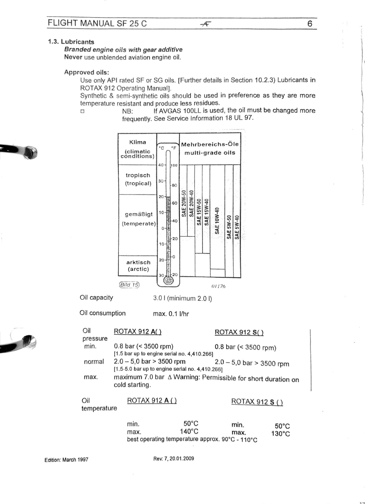
1.
3.
Lubricants
Brande
d engine
oils
wi
th gear additive
Never
use unblended aviation engine oil.
Appro
ved o
ils
:
6
Use only API rated SF or SG
oil
s.
[Further details in Section
10
.2.3) Lubricants in
ROTAX 912 Operating M
an
ual].
Synthetic & semi-synthetic oils should be used in preference as they are
more
temperature resistant and produce less residues.
o NB:
If
AVGAS 100LL
is
used, the oil
must
be changed
more
frequently. See Service Information 18 UL 97.
Klima
Mehrbereichs-Ole
·c
°F
(climatic
~
multi-grade
oils
con
d
itions)
40
100
tr
op
i
sch
(tropical)
30 ·
80
0 0
""
..,
20
.
11
~
3::
0 0
~
60
0 0
Ll>
~
N
<'I
~
UJ w 0
g
em
anigt
10
<(
<(
Ll>
Ll>
l
.
......
,_
en
<n
w w 0 0
40
<(
<(
0
Ll>
"'1'
(tem
pe
rat
e)
'1
<n
en
,...
~
3:
w ·
0 j ·.
<(
.,, .,,
l
20
<n
w w
,____
<(
<(
<n
en
.
10
~
-
$
~
0 --
arktisch
20
~·
~
{a
retie)
•
,_
30
i'20
(Bifd,
_-i_®
-~
-~
-
(J//7(
i
Oil capacity 3.0 I (mini
mum
2.0
I)
Oil consumption max.
0.1
l/hr
Oil ROTAX 912 A
()
ROTAX 912
S()
pressure
min. 0.8
bar(<
3500 rpm) 0.8
bar(<
3500
rpm)
(1
.5
bar
up to engine serial
no
. 4,410.
266]
normal 2.0 -5,0
bar>
3500 rpm 2.0 - 5,0 b
ar
>
3500
rpm
(1
.5-5.0
bar
up to engine serial
no
. 4,410.266]
max. maximum 7.0 bar
t1
Warning: Permissible
for
short
duration
on
cold starting.
Oil ROTAX 912
A()
ROTAX
912
S
()
temperature
Edition: March 1997
min. 50°C min.
max
. 140°C max.
best
operating
temperature approx. 90°C -
110°c
Rev:
7,20.01.2009
50°C
130°C
FLIGHT MANUAL
SF
25 C 7
1.4.
Cooling
system
Sealed cooling system with expansion and overflow vessel.
The
expansion
vessel
is sealed with a pressure cap (with excess pressure and
blow
valve).
Coolant: 50% antifreeze with anti-corrosion additives and 50% water,
for
all
year
round operation.
(see also ROTAX 912 Operating Manual, Section 10.2.1.)
1.5.
Propeller
1) 2 blade fixed pitch a)
Hoffmann
H011AHM-165130for
ROTAX
912
A(1), A(2)
and
A(4)
b)
MT-Propeller MT165R130-2A for
ROTAX
912
A(1), A(2)
and
A(4)
c)
MT-Propeller MT170R135-2A for
ROTAX
912
5(2) and 5(4)
d) MT-Propeller MT175R130-2A for
ROTAX
912
S(2) and 5(4)
2) 2 blade variable pitch a) MT-Propeller MTVtA/175-05 for ROTAX 912A(2), A(4), S(2), S(4)
b)
MT-Propeller MTV21A-C-Fl(CF)175-05 for ROT
AX
912A(3), S(3)
(factory
setting
of
fine
pitch
for
912
A=
12°± 0.2°
for
· .
..
.
912
5 = 14°± 0.2°,see propellercard)
Li
ROTAX
912
A+varia'bie
pitch
propeller:
Not'tof'max:
·':
AtJW.
;
ol
5iiiFitg1
.E
'>.
~~:.'.~~
.
.1
RO
TAX
912 S
+fixed
or
variable
pitch
propeller:'.
On/Vfor
max
'.
AUW~fil5
'
{l/369<fkciYa
~
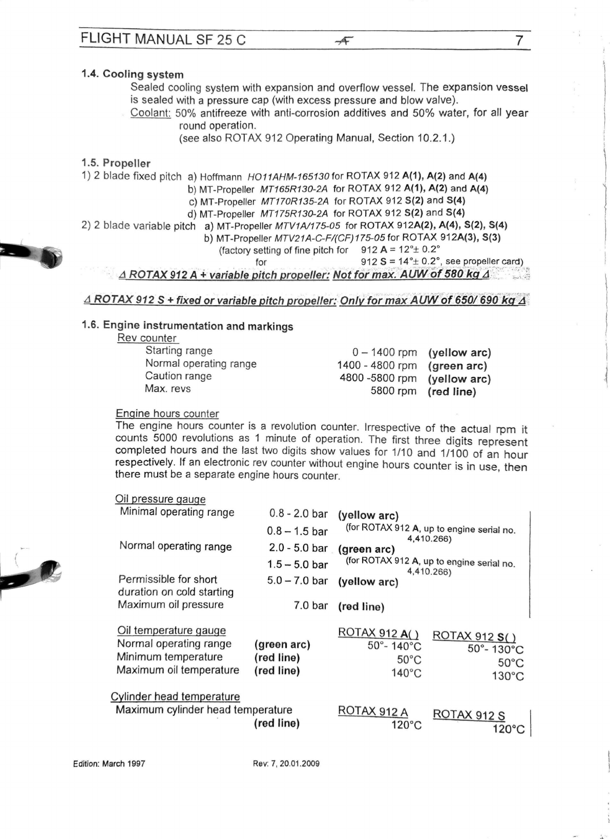
1.6.
Engine
instrumentation
and
markings
Rev
counter
Starting range
Normal operating range
Caution range
0 - 1400
rpm
(yellow
arc)
1400 -4800
rpm
(green
arc)
4800 -5800
rpm
(yellow
arc)
5800
rpm
(red
line)
Max. revs
Engine hours counter
The
engine hours counter is a revolution counter. Irrespective
of
the
actua
l rpm
it
counts 5000 revolutions as 1 minute
of
operation. The first
three
digits
represent
completed hours and the last two digits show values
for
1/10 and 1/100
of
an
hour
respectively.
If
an electronic rev counter without engine hours
counter
is
in u
se
then
there
must
be a separate engine hours counter. '
Oil pressure gauge
Minimal operating range
Normal operating range
Permissible for short
duration on cold starting
Maximum
oil pressure
Oil temperature gauge
Normal
operating range
Minimum
temperature
Maximum
oil temperature
Cylinder
head temperature
0.8 - 2.0 bar
(yellow
arc)
0 8 1 5 b
(for
ROTAX
912 A, up to engine serial
no
.
. - .
ar
4,410.266)
2.0 -5.0 bar .
(green
arc)
1 5 5 0 b
(for
ROTAX
912 A, up to engine serial no.
· - ·
ar
4.410.266)
5.0 -7.0 bar
(yellow
arc)
7.0 bar
(red
line)
(green
arc)
(red
line)
(red
line)
ROTAX
912
A{)
50°- 140°C
50°C
140°C
ROTAX
912
SO
50°-130°C
50°C
130°C
Maximum
cylinder head temperature
ROTAX
912 A
ROTAX
912 s I
· (red line) 12ooc 12ooc
Edition
:
March
1997
Rev:
7,
20
.
01.2009

F
LI
GHT MANUAL SF 25 C 8
1.
7.
Master
sw
itch
The master switch isolates the battery from the aircraft wiring. It is switched
on
at the
start
of
the flight
and
off after the flight
is
completed. It may also be switched off
whilst soari
ng
eng
i
ne
-off. With engine running
only
switch
off
in
case
of
eme
rgency
(e
.g. short circuit,jammed starter relay or similar).
With the option "
one
p
ie
ce co
ckpit
ca
nopy":
(up
to factory SIN 44709)
If
ca
nopy lock
mechani
sm
is
op
en, master switch
is
out of function. Engine is not to start, electric
equipment doesn't work.
1.8.
Circui
t breakers
Except for the starter circuit the aircraft wiring system is protected from overload and
short circuit
by
automatic circuit breakers.
Circ
ui
t breakers Battery
Gene
ra
to
r 25A
20A
A short circuit or overload wi
ll
trip t
he
button of the circuit breaker affected, causing it
to protrude. After correction of
th
e
fa
ult
th
e button
is
pressed
in
again to restore
the
circuit. As the circuit breakers get hot
when
they trip, they should not be pushed in
again
im
med
i
ate
ly
.
If the battery is subject
to
heavy discharge (e.g. lengthy starting attempts in the
wi
nte
r)
the alte
rn
ator
tri
p
may
pop
out
when
the engine
is
running (e.g. in flight).
If
this occurs, push it
in
aga
in after about 2 minutes or the battery will not be charged.
The 20 A generator fuse is
in
the
form
of a fuse switch and located next to the
master switch (which
is
ola
tes
the
battery from the aircraft wiring system, so that it
can
be
isolated from
all
power sources
in
case of emergency. This means
the
alternator
ca
n be is
ol
a
te
d fr
om
the
aircraft wiring system
in
case
of
emergency
by
tripping the fuse switch.
1.9.
Ammeter
When the engine
is
running, it
do
es n
ot
usually indicate a charging current, which
means that the battery is fully
ch
ar
ged.
If t
he
battery charge is low it will i
nd
icate the
battery charge (the
po
inter will
ind
icat
e+
o
r-
).
If a large number of consumers
are
in operation or
if
there are no consumers in
operation, but the engine is not running, the ammeter will indicate battery discharge
(the pointer will indicate
-).
A continuous reading
of
over + 1OA indicates that the
battery
is
no
longer able
to
hold a charge or that the generator regulator is faulty.
Instead
of
this ammeter a Voltage indicator
can
be
used together with a low voltage
lamp (see
MM,
wiring diagram)
1.10.
Antenna
connection
A radio antenna
is
incorporated inside the
fin.
The antenna coax cable is routed from
the fin to a position under the luggage compartment where the remaining length is
coiled and secured. From there it
can
be
routed to the radio. The appropriate
regulations must be observed when fitting the radio.
Edition: March 1997 Rev: 6, 13.
10
.2005
'
l
I
\
I
FLIGHT
MANUAL
SF
25
C 9
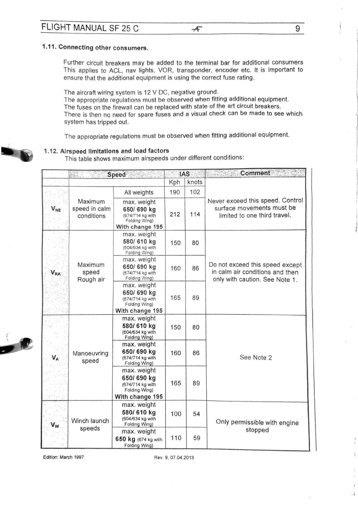
1.11. Connecting other consumers.
Further circuit breakers may be added to the terminal bar for additional consumers
This applies to ACL, nav lights, VOR, transponder, encoder etc. It is important to
ensure that the additional equipment
is
using the correct fuse rating.
The aircraft wiring system is 12 V DC, negative ground.
The appropriate regulations must be observed when fitting additional equipment.
The fuses
on
the firewall can be replaced with state of the art circuit breakers.
There is then no need for spare fuses and a
vi
sual check can be made to see which
sy
stem has tripped out.
The appropriate regulations must be observed when fitting additional equipment.
1.12. A
ir
speed
limitations
and
load
factors
This table shows maximum airspeeds under different conditions:
~\~j:{~:'
···-~-~;~:~~;·t~
~
s
:
p(teCt
~~~0~ff'.:\l~St~~~;.:;:-_
:.;<
·f:_\
1AS
/:.·£
1
~i·1
Sifi
-
'.={&~7;~f:~~;..:;~
ccl~tne~n
~
1
~:~r:~z-~1tz
Kph knots
: All weights 190 102
.··
·- Maximum max. weight Never exceed this speed. Control
V~i
speed in calm 650/ 690 kg surface movements must be
conditions (674/714 kg with 212 114 limited to one third travel.
Folding Wing)
-.
With chanqe
195
max. weight
5801 610 kg 150 80
(6
04
/6
34 kg with
Folding
Win!'.l)
Maximum max. weight
Do
not exceed this speed
exce
pt
.. 650/ 690 kg 160 86
'
VRK
:'.
speed (674/714 kg with
in
calm air conditions and then
-
..
Rough air FoldinQ
Win!'.l)
only with caution. See Note 1.
..
-
--
max.weight
·-
650/ 690 kg
--(674
171
4 kg with 165
89
> Folding Wing)
, -· -With chanQe 195
max. weight
5801610 kg 150 80
(604/634 kg with
. , Foldin!'.l Wino)
max. weight
v,.,
.·
Manoeuvring 650/ 690 kg 160 86
speed (6741714 kg with See Note 2
Folding Win!'.l)
max. weight
650/ 690 kg 165
89
(674/714 kg with
Folding Wing)
-With
chan~e
195
" max. weight
: -580/ 610 kg 100 54
-Winch launch (604/634 kg with Only permissible with engine
·.
·
-vw
speeds Foldlno Wino)
: max. weight stopped
-·
650
kg
(674 kg with 110 59
Folding
Winol
Edition: March 1997 Rev. 9,
07
.04.2013
'.
~
'
I
j
. j
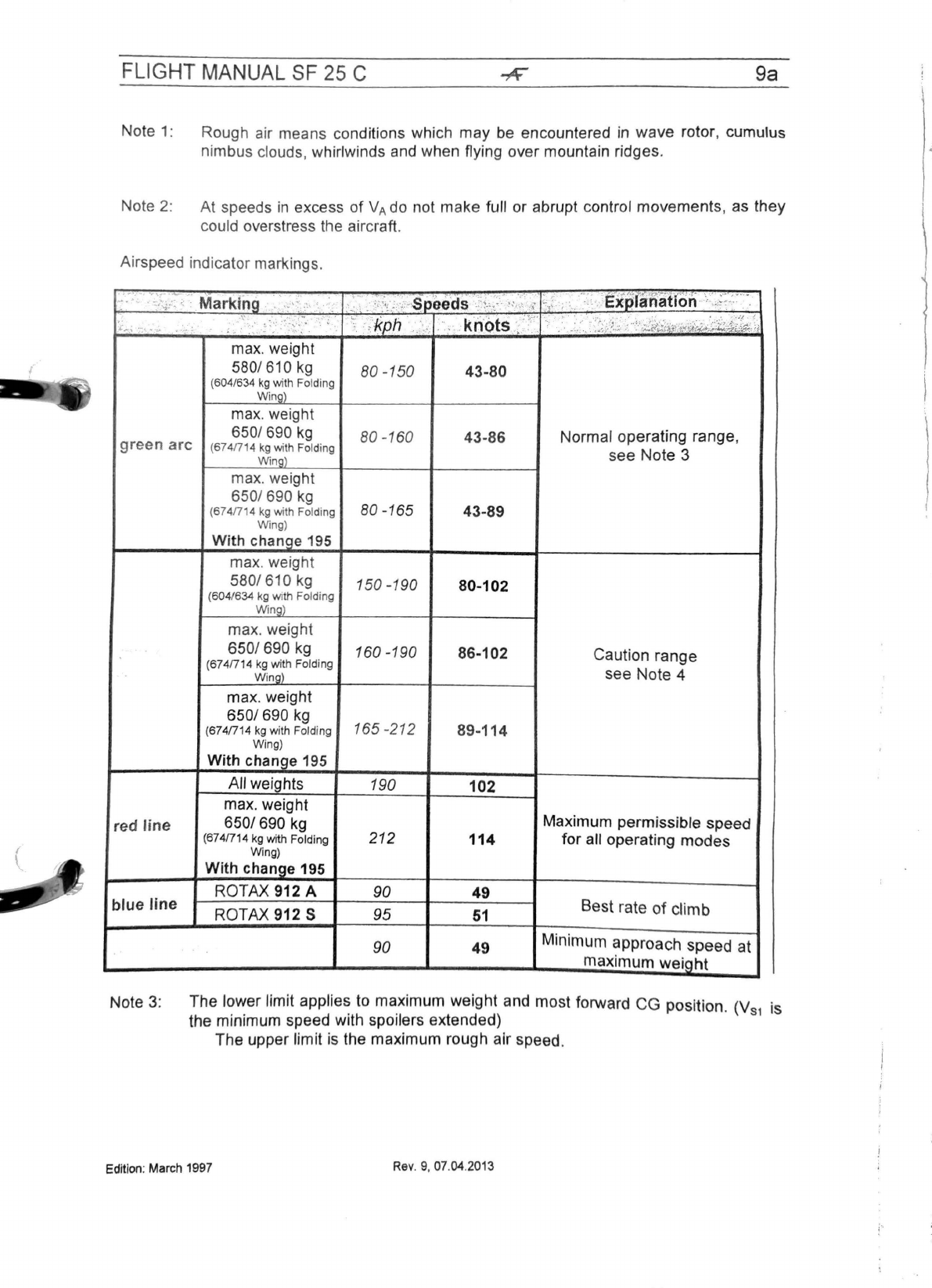
FLIGHT MANUAL SF 25 C 9a
Note 1: Rough air means
co
nditions which may be encountered
in
wave
rotor, cumulus
nimbus clouds, whirlwinds and when flying over mountain ridges.
Note 2: At speeds
in
excess
of
VA
do not make full or abrupt control movements, as they
could overstress the aircraft.
Airspeed indicator markings.
.
:.-:-·;-c\;,-:;2-;
Markfog
.·'
·
:.
, ,
<.
·
:·
_
;:\_,
,-
~peeds
..
'!
.,··
··,_.,::,
-.,.:
:.,
.
·:•,
..
exs)fan
·
atfon
·<,
;~-:::··
·
.
~
...
\
:·:·.
:.~>
. ;
~
\':
:'
.
,·~:
::·:,,
:. ' ; \.·,
kph
·-..·
.·
krl'ots
.,\·
...
.•
'.):·,·.:
..
?···"'
...
>::. ·
:."'
I
v'i-';;
...
-·
ma
x.
weight
580/ 610
kg
80 -150 43-80
(604/6
34
kg
with Folding
Wing)
max. weight
650/ 690
kg
80
-1
60 43-86 Normal operating range,
green
arc
(6741714
kg
with Folding
see
Note 3
Wing)
max. weight
650/ 690
kg
80-165
(674/714
kg
with Folding 43-89
Wing)
With change 195
max. weight
580/ 610 kg 150 -190 80-102
(604/634
kg
with Folding
Wing)
max. weight
6501690
kg
160 -190 86-102 Caution range
(6741714
kg
with Folding
W
in
g)
see Note 4
max. weight
6501690
kg 165 -212
(674/714
kg
with Folding 89-114
Wing)
With change 195
All weights 190 102
max. weight
red
line
6501690
kg
Maximum permissible speed
(6741714
kg
with Folding 212 114 for all operating
modes
Wing)
With change 195
ROTAX 912 A 90 49
blue line ROTAX 912 S 95
51
Best rate
of
climb
90 49 Minimum approach speed at
maximum
weight
Note 3: The lower limit applies to maximum weight and most forward
CG
position. (V is
the minimum speed with spoilers extended) s1
The upper limit is the maximum rough air speed.
Edition:
March
1997
Rev
. 9,
07
.
04
.2
013

FLIGHT MANUAL SF
25
C 10
Note 4: In this range manoeuvres must be conducted with caution and only in calm
air conditions.
.1
Warning: The following
lo
ads must not be exceeded when flying accurately:
With spoilers closed
at manoeuvring speed: +5.3g
at maximum speed +4
.0g
With spoilers extended +3.5g
1.13.
Weights
Empty weight (dependent
on
type
of
undercarriage and
equipment)
Permissible load
in
cluding fuel
Maximum permi
ss
ible AUW (all up weight)
Maximum weight of non-lifti
ng
components
approx.
400kg-450kg
approx
. 200kg
*) 580 kg (with Folding Wings 604 kg)
610
kg (with Folding Win
gs
634 kg)
650
kg
(wi
th
Folding Wings 674 kg)
690
kg (with
Fc;>ld
ing Wings 714 kg)
*
)430
kg/
450kg/490kg/
See Maintenance Manual
pp
. 24 and 25 .
".;.·"
'<·~·
~
·
~~
~
~!L(~t~~~l~
.•
n
.
~~~~J~:!
.
_g)
~~
:~:·:2·
·~a
...
'
4~i
§
fi'\.'8'.!i
::.
~p
p
t~pfi.f~
i.
~
~;'.>~
Edition
:
March
1997
Rev
.
9,
07
.
04.2013
),
I
:
\
FLIGHT MANUAL
SF
25
C
11
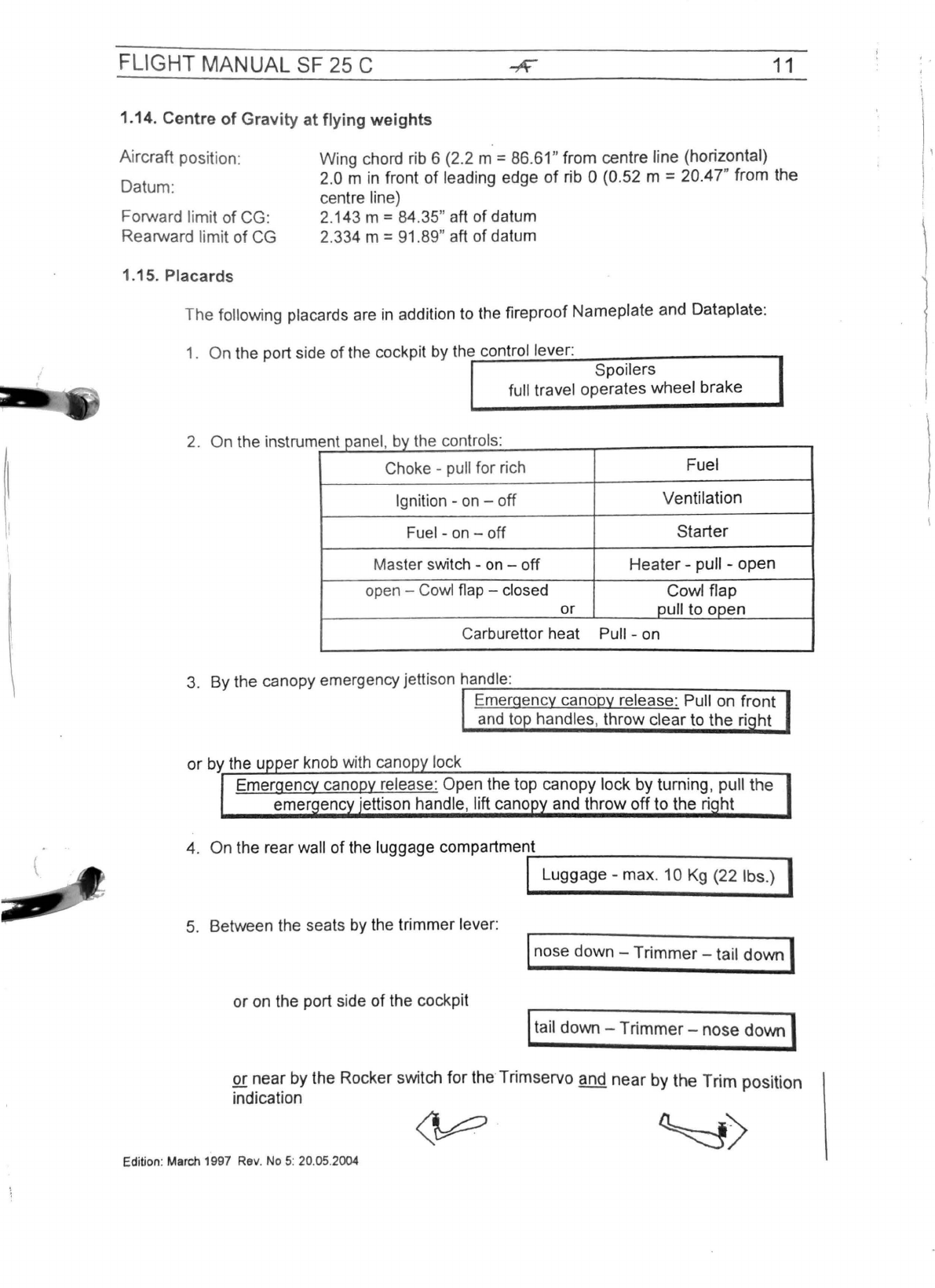
1.14. Centre
of
Gravity
at
flying
weights
Aircraft position: Wing chord rib 6 (2.2 m =86.
61
" from centre line (horizontal)
Datum: 2.0 m
in
front
of
leading edge
of
rib O(0.52 m = 20.47" from the
centre line)
Forward limit
of
CG: 2.143 m =
84
.
35
" aft of datum
2.334 m = 91.89" aft of datum
Rearward limit
of
CG
1.15. Placards
The following placards are
in
addition
to
the fireproof Nameplate and Dataplate:
1. On the port side
of
the cockpit by
the;..c~o::.:.n.:.::tr:..::o:..:..l
.:.:;le:.:.v.::.e:.:.r:
_________
_,
Spoilers
full travel operates wheel brake
2. On the instrum I b h t I
ent pane ,
lV
t e con
ro
s:
Choke -pull for rich Fuel
Ignition -
on
-off Ventilation
Fuel -
on
-off Starter
Master switch -
on
-off
Heater
-pull -open
open -Cowl flap -closed Cowl flap
or oull to ooen
Carburettor heat Pull -on
3. By the canopy emergency jettison
hra-::n:--d_le_
:
____________
_
Emergency canopy release: Pull on
front
and
to handles, throw clear to the
ri
ht
or
by the u
er
knob with cano lock
Emergency canopy release: Open the top canopy lock by turning, pull the
emer enc ·ettison handle, lift cano and
throw
off
to the
ri
ht
4. On the rear wall of the luggage compartmenr-t
___________
_
ILuggage -max. 10
Kg
(22 lbs.) I
5. Between the seats by the trimmer lever: lnose down -
Trimmer
-tail
down
I
or on the port side of the cockpit ltail down -
Trimmer-
nose
down
I
or near by the Rocker switch
for
the Trimservo and
near
by the
Trim
position
indication
~
·
~>
Edition:
March
1997
Rev
.
No
5:
20
.
05
.
2004
'.'
r
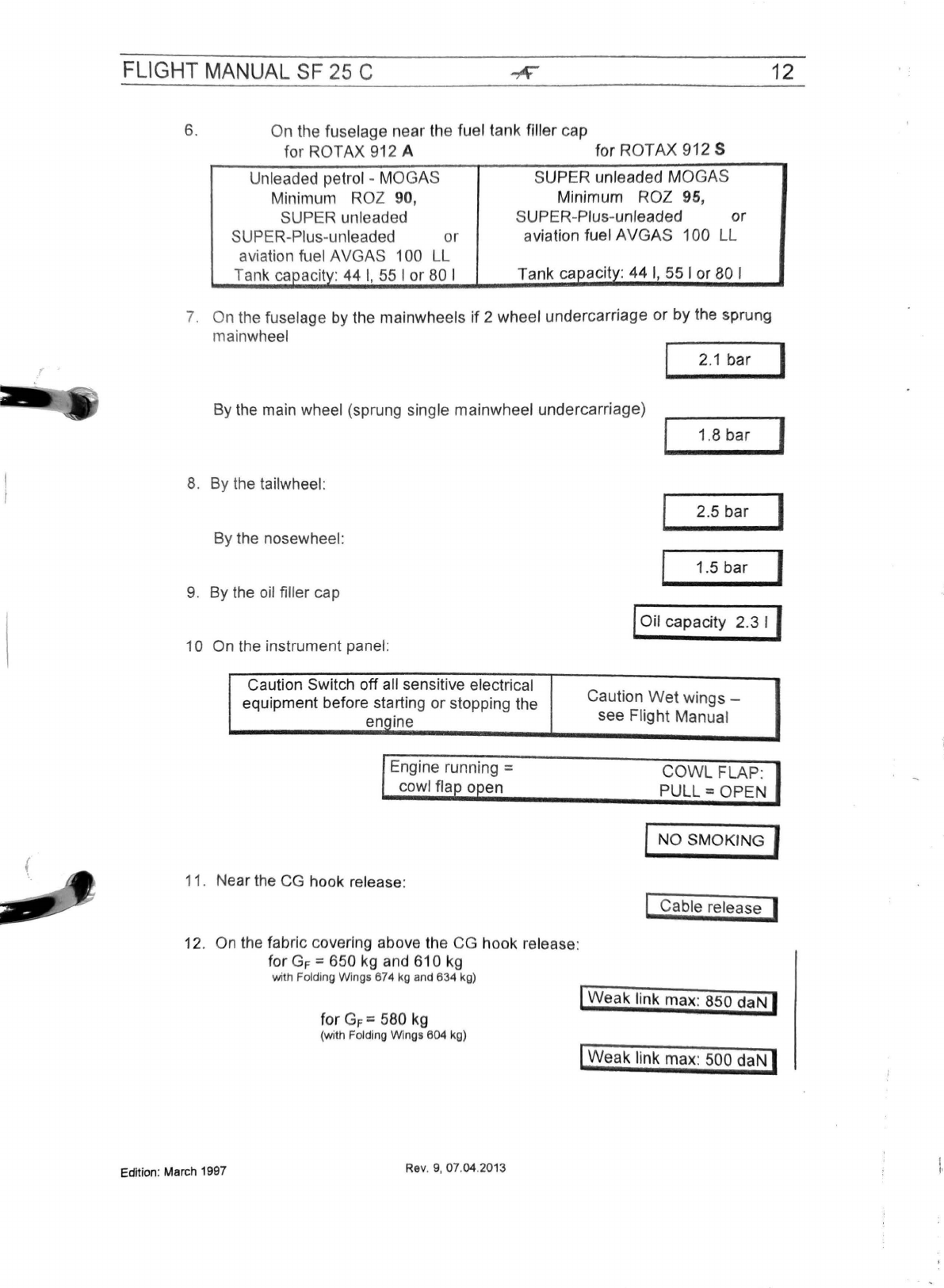
FLIGHT MANUAL SF 25 C
6. On the fuselage near the fuel tank filler cap
for
ROTAX
912 A for
ROTAX
912 S
Unleaded petrol -
MOGA
S
Minimum ROZ 90,
SUPER unleaded
SUPER-Plus-unleaded
or
aviation fuel
AVGAS
100 LL
Tank caoacitv: 44
I,
55 I
or
80 I
SUPER
unleaded
MOGAS
Minimum
ROZ
95,
SUPER-Plus-unleaded
or
aviation fuel
AVGAS
100 LL
Tank
capacitv:
44
I,
55
I or 80 I
7.
On the fuselage by the mainwheels
if
2 wheel undercarriage
or
by
the sprung
mainwheel
12
2.1
bar
I
By the main wheel (sprung single mainwheel undercarriage)
1.8
bar
I
8.
By the tailwheel:
By the nosewheel:
9. By the oil filler cap
1O On the instrument panel:
Caution Switch off all sensitive electrical
equipment before starting
or
stopping the
engine
Engine running =
cowl fla o en
11. Near the
CG
hook release:
12
.
On
the fabric covering above the CG hook release:
for
GF
=650
kg
and
61
O
kg
with
Folding
Wings
674
kg
and
634
kg)
for
GF
=580 kg
(with
Folding
Wings
604
kg)
Edition:
March
1997
Rev
.
9,
07.04.
2013
2.5
bar
I
1.5
bar
f
lOil capacity 2.3 I f
Caution
Wet
wings -
see Flight Manual
COWL
FLAP:
PULL=
OPEN
INO SMOKING I
l Cable release J
I
Weak
link
max
: 850
daN
I
I
Weak
link
max
: 500
daN
I
FLIGHT
MANUAL
SF
25 C
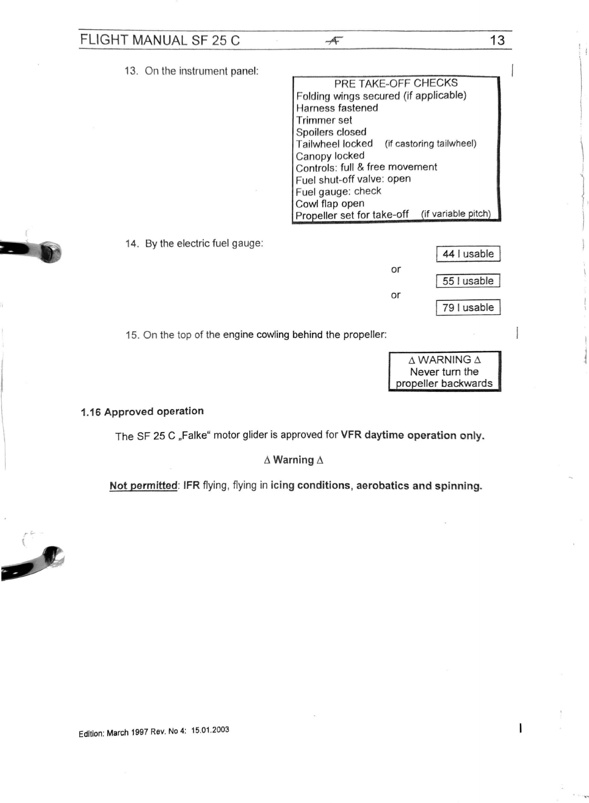
13.
On
the instrument panel:
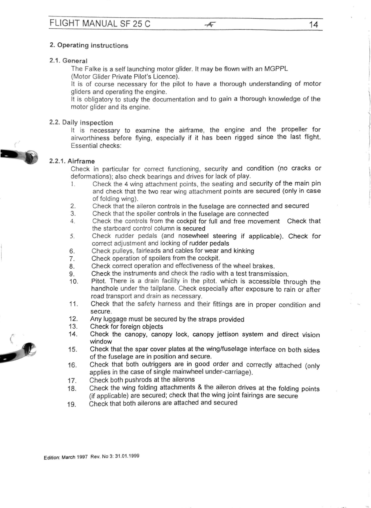
14. By the electric fuel gauge:
PRE
TAK
E-OFF
CH
E
CKS
Folding wings s
ecur
ed
(if
applicable)
Harness fastened
Trimmer
set
Spoil
er
s closed
Tailwheel locked (if castoring
ta
il
wheel)
Canopy locked
Controls: full & free
movement
Fuel shut-
off
valve:
open
Fuel gauge: check
Cowl flap open
Propeller set
for
take-off
(if vari
ab
le pitch)
13
or
or
I
44
I
usab
le I
I55 I
usab
le I
I
79
I
usab
le I
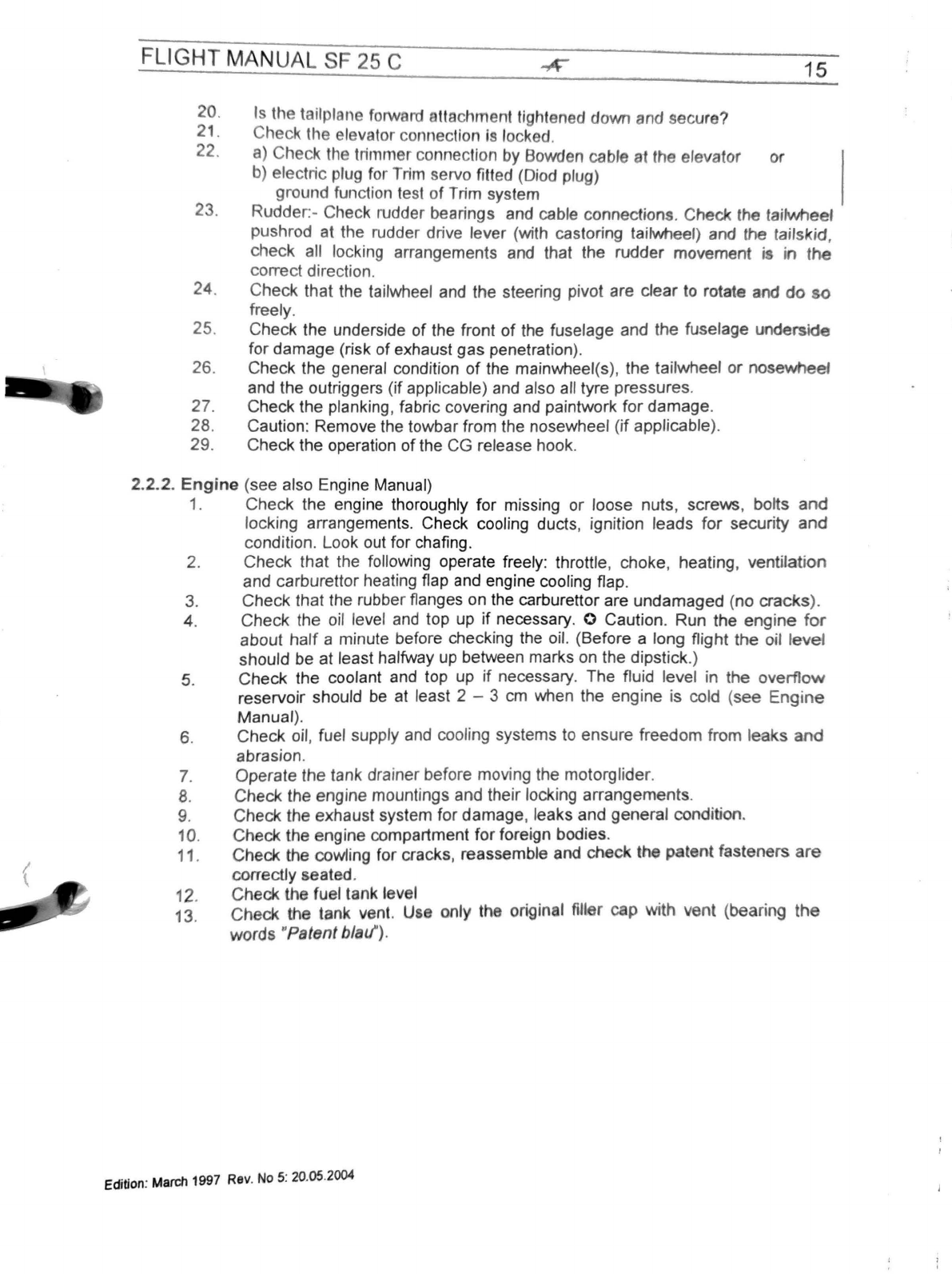
15.
On
the top of the engine cowling behind the propeller:
1.16 Approved operation
~WARNING~
Never
tum
the
propeller
backwa
r
ds
Th
e
SF
25 C
,,
Falke"
motor
glider is approved
for
VFR daytime operation only.
/l.
Warning
/1
Not permitted: IFR flying, flyi
ng
in icing conditions, aerobatics and spinning.
Edition:
March
1997 Rev.
No
4:
15
.
01
.2003
I
; j
\
\
i
(
)
I
.l
FLIGHT MANUAL
SF
25 C
2. Operating
instructions
2.1. General
The Fal
ke
is a self launching motor glider. It may
be
flown with
an
MGPPL
(Motor
Gl
ider Private Pilot's Licence).
14
It is
of
course necessary for the pilot
to
have a thorough understanding
of
motor
g
li
ders and operating the engine.
It is
ob
li
gatory to study the documentation and to gain a thorough knowledge
of
the
motor g
li
der
and
its engine.
2.2. Daily ins
pection
It
is
necessary
to
examine the airframe, the engine and the propeller
for
ai
rworthiness before flying, especially if it has been
ri
gged since the last flight.
( Essential checks:
2.2.1.
Airframe
Check
in
particular for correct functioning, security and condition
(n
o cracks
or
deformations);
also
check bearings
and
drives for lack
of
play.
I. Check
the
4
wing
attachment points, the seating and security
of
the main pin
and check that
the
two
rear
wing
attachment points are secured (only in case
of
fo
lding wing).
2. Check that the aileron contro
ls
in
the fuselage are connected and sec
ur
ed
3. Check that the spoiler
co
nt
ro
ls in
the
fu
selage are connected
4. Check
th
e
co
ntrols from
th
e
cockp
it for full
an
d free movement Check
th
at
the starboard control column is secured
5. Check rudder pedals
(and
nosewheel steering if app
li
cable
).
Check
for
correct
ad
j
us
tment
and
locking of rudder pedals
6.
Check pulleys,
fa
irleads
and
cables
fo
r wear and kinking
7.
Check operation of spoilers from the cockpit.
8.
Check correct operation
and
effectiveness of the wheel brakes.
9. Check the instruments
and
check the radio with a test transmission.
1O. Pitot. There
is
a drain facility
in
the pitot. which
is
accessible through
the
handhole under the tailplane. Check especially after exposure to rain or after
road transport and drain
as
necessary.
11.
Che
ck
that the safety harness
and
their fittings are
in
proper condition and
secure.
12. Any luggage must
be
secured
by
the straps provided
13. Check for foreign objects
14. Check the canopy, canopy lock, canopy jettison system and direct vision
window
15. Check that the spar cover plates
at
the wing/fuselage interface on both sides
of
the fuselage are
in
position
and
secure.
16
. Check
tha
t both outriggers
are
in
good order and correctly attached (only
applies
in
the case of single
ma
i
nwh
ee
l
un
der-carriage).
17. Check both pushrods at
th
e a
il
e
ron
s
18. Check the wing
fo
l
di
ng att
ac
hm
e
nt
s &
th
e
ai
leron drives at the folding points
(if applicable)
are
secured; check
th
at the wing joint fairings are secure
19. Check that both
ai
lerons are att
ac
hed and secured
Edition: March 1997 Rev. No 3:
31
.
01
.1999
FLIGHT
MAN
UAL
SF
25
C 15
20.
21.
22.
23.
24
.
25.
26
.
27.
28.
29.
Is
the tailplane forward ttachment tightened down and secure?
Check
the
elevator connection
is
locked.
a)
Check
the
trimmer connection
by
Bowden cabl
a1
the elevator or
b) electric plug for Trim servo fitted (Diod plug)
ground function test
of
Trim system
Rudder:- Check rudder bearings and cable connections. Check the taifwf'leel
pushrod at
the
rudder drive lever (with castoring tailwheel) and the tailskid,
check all locking arrangements and that the rudder movement ·
in
the
correct direction.
Check
that the tailwheel and
the
steering pivot are clear to rotate and
do
so
freely.
Check the underside
of
the front
of
the fuselage and the fuselage underside
for
damage
(risk
of
exhaust
gas
penetration).
Check the general condition
of
the mainwheel(s),
the
tailwheel
or
nosewheef
and
the
outriggers
(if
applicable) and also all tyre pressures.
Check the planking, fabric covering and paintwork
for
damage
.
Caution: Remove the towbar from the nosewheel (if applicable).
Check the operation
of
the
CG
release hook.
2.2.2.
Engine
(
see
also Engine Manual)
1.
Check
the engine thoroughly
for
missing
or
loose
nuts
, screws, bolts and
locking arrangements. Check cooling ducts, ignition
leads
for
secur
ity and
condition. Look out for chafing.
2.
Check
that
the following operate freely: throttle, choke, heating,
ve
ntilation
and carburettor heating flap and engine cooling flap.
3.
Check
that the rubberflanges on the carburettor are
undamaged
(
no
cracks
).
4.
Check
the oil level and top up
if
necessary. 0 Caution. Run
the
eng
ine
for
about
half
a minute before checking the oil. (Before a long flight
the
oil
level
should
be
at least halfway up between marks on the dipstick.)
s.
Check
the
coolant and top up
if
necessary.
The
fluid level in
the
overflow
reservoir should be at least 2 - 3 cm when the engine is cold (
see
Engine
Manual).
6.
Check
oil, fuel supply and cooling systems to
ens
ure
freedom
from
leaks
and
abrasion.
7. Operate the tank drainerbefore moving
the
motorglider
.
B.
Check the
engine
mountings and their locking
arrangeme
nt
s.
9. Check
the
exhaust system
for
damage
, leaks
and
genera
l condition.
10. Check
the
engine compartment
for
foreign bodies.
11
.
Check
the
cowling for cracks, reassemble and
check
th
patent
fasteners
are
correct
ly
seated.
12
.
Ch
eck
the fuel tank level
13.
Check
the tank vent.
Use
only
thi
origin I fll r P
with
vent
(bearing
the
words
"Patent
bla
l/).
Edition:
March
1997
Rev
.
No
5:
2-0
.
05.2004
' j
FLIGHT MANUAL SF 25 C
16
2.2.3.
Propeller
(see also Propeller Handbook)
2.2.3.1.
Electric
Constant-Speed-Propell
er
MTV1A1175-05
and
Hydraulic
Constant-Speed-Propeller MTV21A-C-F/(CF)175-05.
1. Check the condition of the blades and the spinner (no cracks).
2. Check for play at the propeller tips (up
to
3 mm
is
permissible).
3. Check for play
in
pitch
at
the prope
ll
er tips (up to 2° is permissible).
4. Check propeller blades for cracks and that the leading edge protective tape is
intact.
5. Propeller hydraulics: operating pressure 125
~si
(9.? bar). Check every
50
hours
and
top
up
as
necessary (using nitrogen
1f
possible). Only for MTV
1A
6. Check propeller pitch movement with master switch on and
~ngme.
~ff.
7. Check the commutators
and
brushes together with the electrical wmng.
2.2.3.2. Fixed pitch propeller . .
1. Check condition of the blades. (no indentations or sphntenng)
2.
Check the spinner for cracks.
3.
Is
the leading edge protection intact?
2.3. Pre
take-off
checks
1. Folding wings secured (if ap
pl
icable)
2.
Canopy closed
and
locked
3.
Safety harness secure
4.
Trimmer set for take off
5.
360° tailwheel locked (if applicable)
6.
Spoilers closed
and
locked
7.
Check for full
and
free movement of the controls
8.
Fuel shut-off valve
open
9. Sufficient fuel
in
tank
10. Cowl flap open
11. P
ro
pe
ll
er set to take-off pitch (if applicable)
2.4.
Starting
th
e
Motorglider
Has
th
e pre-flight inspection been completed? Move the throttle to full power,
check
for freedom
of
movement
and
full travel
and
return
to
idle position.
ti Caution: Wheelbrake on,
ignition
off
In
cold weather conditions turn the propeller several times by hand before starting*
and check for
un
usual noises
and
stiffness
in
the motor a
nd
al
so
for
even
compression. (See also E
ng
i
ne
Manual: Check the mechanical components) Before
starting the engine, close the
ca
nopy. Before startin
g,
check that all the electrical
trips (but not those
of
sensitive electronic equipment such
as
radio, transponder,
Avionics master switch etc.)
are
pressed hom
e.
After the pilot has confirmed that
the
propeller area
is
clear, start the engine.
With the option "one piece cockpit canopy" (starting from factory serial number
44710): If canopy lock mechanism is open,
th
e push button for the engine starter is
out
of
function. Engine
is
not
to
start
NEVER turn t
he
prope
ll
er backwards
ti Also ifthere is a vacuum pump for gyroscopic instruments (or damage
to
the pump blades will result).
Ed
ition: March 1997 Rev. 6:
13
.
10
.2005
)
I
l
I
j
Table of contents


