Helio HT-295 User manual

HELIO
AIRCRAFT
COMPANY
HELlO MODEL
HT-295
OWNERS
MAN’UAL

SEcTLcm
x
Gemma
Description of Airplane
PAGE
c
Descriptfon
af
Structure
-
-
-
*
-
”
-
-
*
-
-
-
-
-
-
-
-
-
-
1
Ailerons
and
Interce$tore-
-
-
-
-
-
-
-
-
-
-
-
-
-
-
-
-
-
-
2
2
2
2
SECTION
XI
Flight And Operating xastructions
--
I
Flight
Controls
c
(I)
0
a
II,
e
I,
e
I
e
m
a
L
a
m
*
m
e
w
m
a
m
Ir
Pre-Flfght
Inspection
a
m
e
a
a
a
a
m
m
-
c
w
m
m
.
r
m
m
w
o
Operation
a
-
-
m
0
a
m
a
-
-
-
a
a
-.
a
a
a
a
-
a
a
-.
.
w
General Operating
Instructfom
And
Lintitations-
-
-
-
-
-
-
-
Pilot
Check
List-
Ir
a
lit
m
m
a a a a
a
a
c
a a
I
a
a
a
m
a
m
a
Pilot Emergency Check
List---
-
-
-
-
-
-
-
-
-
-
-
-
-
-
-
-
Summary
of
Operational
Afrspeab-
-
-
-
-
-
-
-
-
-‘-
-
-
-
-
Take-Off,
Cruise
and Landing
Technfques
-
-
-
-
-
-
-
-
-
-
-
Cross-Wind Take-Off
md
Landing
Techniques-
-
-
-
-
-
-
-
-
-
Mi8cellaneoua
Provisions
-
*
-
-
-
-
-
-
-
-
-
-
-
-
*
-
-
-
Brake System
Schmatic -
-
-
-
-
-
-
-
-
-
-
-
-
-
-
-
-
-
Fuel System SePtematic
-
-
*
-
-
-
-
-
-
-
*
-
-
-
v
-
-
-
2
2
3
4
6
7
10
12
13
13
21
24
25
26
i

f
. SECTION I
General Description of
Airplane
‘i
The
W-295
is a high wing monoplane.
The wing is fully cantilever and
of all metal construction. The fuselage cabin section is a metal
covered tubular structure and the aft section is all metal
semi-
monocoque.
The tail surfaces are of all metal construction. Power
is supplied as follows:
Model
I-IT-295
Engine
Propeller
Is-
Lycoming (295hp) GO-480-GlA6 Hartzell
Constant speed
96" dia.
The
Model
WT-295 is a six place plane, The occupants are seated
in two individual adjustable front seats, two individual middle
seats with two reclining posftians, and a two place rear seat,
Entrance to the front seat is through a left front door. Entrance
to the rear seats
fs
through a rear right door, the sill of which
is at
floor
level height for easy
loadbg
and unloading, The rear
seat is easily removable
i'or
added cargo space.
'
Surface control
is
by conventional wheel and rudder pedals.
Provisi
are made for wheel, rudder pedals and brakes on the right
sfde,
Toe
brakes are provided on the left side. (Brakes for the right side are
optional*) The flaps are actuated by an electric motor on the 1700
series.
Longitudinal trim is by an elevator trim tab actuated by an
electric motor on the 1700 series.
The airplane is equipped with long span slotted flaps and full span
leading edge slats for high lift operation. Lateral control is
obtained by short span Frieze ailerons operated in conjunction with
leading edge interceptors, The latter are provided for low-speed
control,
Pitch change is obtained with an all-moving horizontal
tail.
Directional control is obtained with a conventional type rudder.
The engine
section
is composed of the engine installatfan, oil cooler,
carburetor,
ram air filter screen, oil system piping, fuel
system
piping,
electrical system, cowl flap system and the necessary mechanical
control units* The engine section is completely enclosed by
aluminum wrap-around cowl. The engine mount is a welded steel tube
structure bolted to the forward end of the fuselage. The engine is
suspended on the engine mount by four vibration isolators.
The
fire-
wall is of stainless steel.
Description of Structure
-
WING PANEL. The wing is a two-panel full-cantilever unit and all metal
construction.
Ribs are formed 2024
alclad
members.
The main spar
consists of 2024
alclad
web and 2024 extruded angle capstrips.
The
rear spar is a 2024
alclad
formed channel.
The wings are attached
to the fuselage through a welded steel truss.
l
1
c
AILERQNS
AKD
INTERCEPT0RS.t
The ailerons are the Frieze type, of
2024
alclad
diagonal rib truss structure, fabric covered,
They
are
hinged at both ends and operated by a push-pull tube at the
ce&ex,
The interceptors consist of heavy aluminum alloy curved plates (inboard)
and forward of each
aileron).
They emerge from the wings
incon-
junction with the ailerons.
FLAPS.
The flaps are of a single spar all-metal
constructfon,
They
are supported to the wing structure by three flap tracks and are
actuated by push-pull tubes at the center and outboard tracks,
TAIL
GROUF.
The tail group is composed of a vertical fin and rudder,
and an all-movable horizontal surface equipped with an anti-balance
and
t&n
tab.
All tail surfaces are of aluminum alloy construction.
FIN:
Two-spar construction,
RUDDER:
Single-spar construction
STABILATUR: Sfngle-spar
construction
FUSELAGE. The forward fuselage structure is a welded steel tube
truss.
It is covered with
alclad
sheet in the cabin section; the
remaining portion is semi-monocoque.
LANDING GEAR.
-
The main landing gear is the Spring Steel type mounted
in a box
section
of the fuselage structure.
The Nose Wheel is the
air-oil shock strut type and is attached to the engine mount.
§PECXFZCATECMS
Gross Weight
Empty Weight
Wing Span
Wing Chord
Wing Area
(Slats retracted)
Overall Length
Aileron Area
(Each Surface)
3400
lbs,
Fuel Capacity (Useable)
2023 lbs.
Octane Rating
39 ft.
Oil Capacity
72 in.
Power
Plant
231
sq.
ft,
Take-off Horsepower
30 ft. 4 in. Normal Rated Horsepower
10135
sq. ft.
Flap Area (Each Surface)
Slat Span (Each Wing) 203.93 in.
Stabilator Area
Rudder and Fin Area
24.40 sq. ft. Wheel Tread
58,s
gals.
100 (Min.)
12 qts. (Max.)
10 qts. (Desired)
GO-480-GlA6
Lycoming
295
280
19.05
sq*
ft.
37.50
sq,
ft.
102.00
in.
2
SECTION
II+F&IGHT,AND
OPERATING
INSTRUCTTONS
c
The
HT.295
incsrporates
flight control devices to insure safe
flight at slow air speeds without detriment to high-speed flight.
The cockpit
contmls,
however,
are
conventional and their operation
is the same as in any
ather
fixed-wing airplane. The exceptional
degree of control is obtained by the use of
reading
edge slats,
large flaps,
interceptors and a fully movable
horimntal
tail
surface with its anti-balance tab.
Each
contml
is described in
detail
in
the following discussions.
AILERONS.
The ailerons are operated in a
conventionaL
manner by
efther
of the dual control wheels.
In
addition to the
ailerms,
the control wheels actuate interceptor blades which extend through
the upper surface of the wing directly behind the outboard slat,
The ailerons are
csnventional
and they provide the
nomal
corrective
forces at high speeds. The interceptors provide the extremely
positive lateral control at
the
slowest speeds obtainable, This
-
control is so effective that it
is
possible to overcame the effect
of full rudder in a stall by use of the aileron-interceptor
control and roll into a turn
in
the opposite
direc3tion.
The aileron
interceptor combination produces a very high
rate
of
sollat
all
speeds with comparatively small control movements. Violent, full
throw contra1 movements are not necessary
ta
produce satisfactory
xates
of roll at all airspeeds.
RUDDER.
The rudder and controls are conventional. The rudder pedals
are ground adjustable
to
four positions.
Toe brakes are provided
on the left-hand pair of pedals.
SWLBZLATOR.
The horizontal tail surface, or
stabilator,
is a single
movable surface instead of the usual elevator and horizontal
stabilizer.
The control operation is
canventional
and control feel
and reaction in the cockpit are the same as in other aircraft.
There are two tabs attached
to
the horizontal surface, a trim
tab and an anti-balance tab.
The right hand surface has the
anti-
balance tab attached to it. It is an anti-balance tab because
it moves in the same direction as the surface, thus providing a
force which always returns the surface to the trim position, The
actuating arm and pivot paint for this tab, which is mounted
otz
the fuselage directly under the fin, should be inspected as a
part of the daily pre-flight inspection.
The trim tab is located an the left hand surface. It is of the
conventional type with a trim tab position indicator located on
the
instrment
panel.
sup
l
The leading edge wing slats operate fully automatically
by the air-loads on them. Their use provides the very slow
speeds possible with this airplane. All slats are fully visible
from the cockpit, they should normally be open on the final
approach,
If it appears that any
of
the
four
slats have stuck,
it is advisable to land about 10 MPH faster than the minimum landing
speed.
3

It
should be noted that the lateral and
dixectiana.1
control
is
so
effective that through their normal use, it is possible to overcome
the effects of both slats remaining closed on one side.
c
FLAPS l
All 1700 series aircraft have electric powered flaps as
standard with
a
flap position Indicator on the instrument panel.
Full flap can be used for landing under all normal wind conditions.
Shortest take-off runs,
under
standard air, sea-level conditions,
are performed
with
30'
flaps,
although
ZOO
will give a better rate
of climb once the airplane is airborne and provides better take-off
at higher altitudes,
or
with maximum
gross
loads,
B.
PRE-FLIGHT
INSPECTIUN
s
1
e
Check interior of cabin for Fuel Valve "ON", ignition
and
Master
Switch "OFF",
mixture
control "Idle
CUTOFF”, remove gust
lock,
2
l
Pull propeller through several revolutions
and
inspect blades for
nicks and
cracks.
3
e
Open engine cowl;
check oil level
and
inspect fuel
rend
oil lines
for leaks.
Give engine compartment
a
complete visual check.
4
(I
Check
nose
wheel
olea
shock
strut
and
tires
for
proper
inflation,
5
8
Check main gear brakes and lines for leaks and security.
6
l
Drain
sediment
bawl,
(Accessible through small door under the
forward windaw on right side fuselage.) Drain auxiliary fuel
tanks if applicable. (Drains located on the bottom of each wing,)
7
a
Check fuel laad and make
certain
that the fuel caps are firmly
secured on the
fillernecks.
8
&
Check slat operation for freedom of movement and any unusual play.
9
*
Move
all control surfaces and check security of
all
hinge bolts
and push-pull tubes,
10
l
Check security of anti-balance tab on horizontal tail and its
pivot point on the fuselage,
11
0
Remove cover
if
installed on
pitot
tube, and make sure it
is
free
from dirt or other obstructions,
CAUTION:::
WHEN CLEANING OR WAXING AIRPLANE, DO NOT ALLOW
WAX OR CLEANER TO PLUG STATIC VENT
HOLES,e,,,,,,
After entering the airplane and before starting the engine:
1
0
Adjust and fasten the combination seat and shoulder straps.
4

2
a
Check all
controfs
for
freedom
af
mavement
and proper direction.
3
l
Pnsure
that all
cargo is secured and that the load is properly
located,
4
0
Check
positim
of electrical and ignition switches.
5
l
Open cowl flaps.
ENGINE
STARTING.
The following starting procedure is taken from the
Lycoming Operator's Manual,
A copy of the Lycoming
rfanual
is furnished
with each airplane and is considered
a
part of this manual,
Lock
the wheels by efther wheel brakes
OT
chocks,
I
Set the propeller control lever all the way forward in INCREASE
RPM
position.
Be sure fuel valve is
ttUNtt.
set throttle
to
l/4
open position*
Place mixture
control
in the
"Idle Cut-off" position (Full out).
Turn on auxiliary fuel pump and check pressure.
Turn ignition switch to extreme right and push (this energizes
starter)*
NOTE
On aircraft with control lock pin
located
on pilot's
control wheel shaft, it is necessary to remove the pin
before attempting to start the engine, The aircraft
is
designed
so
the
starter
circuit
is inoperative with the
control
lockpin
installed.
The magneto circuits are not
involved in
any
way.
When the engine begins to fire, immediately put mixture control in
Full Rich position (full in) and allow ignition switch to return to
"both'" mag position. CAUTION
-
If engine fails to start immediately,
return mixture control to Idle Cut-off position. Failure
to
do so
will
create
an excessive amount of fuel in the carburetor air scoop
constituting a fire hazard.
"Vapor locking is not a
common
occurrence on Lycoming
Go-480
engines,
However
9
under certain circumstances it can occur,
i,e,
when runway
and ramp temperatures exceed
lOOoF
particularly on sunny days and at
airfields of high elevation where temperatures exceed
80*F,
During
these conditions vapor locking can occur after a hot engine has been
shut-down and a start is attempted within a period of up to one hour
after initial shut-down.
Vapor lock symptoms are; zero fuel pressure
with the electric fuel booster pump on, and by hearing an unusual
sound
in
the booster pump which
indicates it is cavitating rather
than
pumping.
5

When it is suspected that a vapor lock exists, the
follawfng
procedures should be used:
Fuel selector ON, electric fuel booster
Pump
ON,
throttle opened
l/4,
push mixture control to full rich and
leave there until fuel pressure builds up and cavitating sound
disappears,
then return migture control
ta
idle
cut-off and proceed
with normal starting sequence. If a solid vapor lock exists, the
engine primer is usually ineffective until the vapor lock
2s
broken
by the method mentioned above."
If
of1
pressure does not build up after 30
seconds
running, stop
engine and determine trouble.
Check Engine Driven Fuel
Pump
for proper pressure by turning off
auxiliary fuel
pumps
I
Initial warm up should be at 1000 to 1200 RPM.
ENGINE
WARM-UP
Engine is warm enough for take off when the throttle can be opened
without backfiring or skipping.
,
Check magnetos at 2600
RPM.
Drop off should not exceed 175 RPM on
either magneto and should be withfn 50 RPM of each other.
Exercise pro eller
at 2200 RPM. Pull control to decrease RPM, note
drop to 1275
P
50 RPM,
Cowl flaps should be open for all ground operation (pull handle out).
Avoid prolonged ground operation as it will cause overheating.
For further
information
on cold weather starting and engine operation,
consult the Lycoming Operator's Manual.
c
9
OPERATION
TAKE-OFF: Prior to take-off, a check should be made to insure that;
I
1
e
Weight and Balance is
currect.
2
l
All occupants have properly secured the combination seat and
shoulder straps,
3
l
Stabilator
trim
tab set.
4
l
Flaps are extended
3Oo
or less for take-off.
5
l
Cowl flap lever is pulled out to fully open cowl flaps.
6
l
Propeller control
is
pushed in for maximum
RPM*
(3400
Max.)
7
l
Fuel selector valve is
"ON".
8
0
Parking brake control is *'OFF" position.
9
(,
Auxiliary boost pump
'*ON".
6

As
SQQ~
as possible after take-off,
reduce RPM
t=o
the maximum
continuous setting
(3000
RPM) and retract the flaps.
Take-off
power may be used for
8
maximum of five (5) minutes, but it is
advisable
to
reduce
power
a6
soon
as
practical. Best rate of
climb is obtained at 65
MPH
IAS
flaps down, and at 90 MPH
IAS
flaps up at
MET0
power.
A cylinder head temperature gauge is
provided as standard equipment, and power,
ctowl
flaps, and speed
settings should be selected
to
maintain the cylinder head
temperature somewhat less than
475’F.
The maximum
pernt.lssible
is
45O*F.
at
cruise
power,
For take-off and normal rated power,
the limit is
475*F.
LARDING.
During
the let down prior to the landing
8pproach:
1
e
Close
tile
cowl flaps so that the engine does nat cool
too
rapidly.
2
e
Open throttle occasionally to clear out
engine
and keep warm.
Prior to turning into the base leg in the landing
approach:
3
l
Auxiliary Boost Pump
"ON".
,
4
0
Extend the flaps to the desired position
(Maximum
flap speed is
80 MPH) l
5
l
Set propeller control to 3000 RPM.
TAXI
1
l
Retract
Flap.
2
&
open
cowl
flaps.
3
l
Auxiliary Boost
Pump “OFF”.
STOPPING ENGINE
1
l
Pull mixture control full
out
to the idle cut-off position,
(Apprax.
1000 RPM).
2
l
After
the engine stops,
shut off the ignition switch and then the
master
and
generator switch.
3
l
Leave fuel valve in the
*'ON"
position,
4
l
If
the aircraft is to be parked overnight,
push
the
mixture
control
in
l/3.
D.
GENERAL OPERATING INSTRUCTIONS AND LIMITATIONS
This airplane
is
licensed in
the
normal
category
and no
acrobatic
maneuvers, including spins, are approved.
7

5
PROPELLER
LIMITATIONS. None.
Avoid high engine speed (2800 RPM or higher) in
cambination
with
low manifold pressure operation
(under
15"),
Avoid
rapid closing
or opening of the
throttle
(especially
from
a high
RPM
and
manifold
pressure condition).
STALLS AKD SPINS,
The leading edge slats and the restricted nation
of the
stabilator
makes it impassible to fully stall the wing on
the HT-295.
As the minimum speed obtainable
is approached
with the
yoke
full back, a center section separation causes tail buffeting,
A slight aileron nibble is also noticed as the minimum
speed
is
approached.
Minimum
speed
power-off with the flaps down is
apprax-
imately
40
WH
IAS.
This varies with
load
and
C.G,
cbndition.
Voluntary
spins
are
prohibited,
Although the airplane can be
forced, under certain conditions, into
auto-xotatfon which is technically a
spin&,
this maneuver is not the
same as the well
known
"tailspin'*
in that it
cannot
occur accident-
ally
and
contrary
to the pilot's movement of
the
controls.
Na
dive
nor forward movement of the control wheel is required for recovery.
Recovery is effected by the normal
use
of either the aileron
or
rudder control.
SPEED LIMITATIONS.
The
Never-Exeed
Speed
(We)
for the
HT.295
is
200 MPH
C.
A.
S. A
red
line
appears
on the airspeed instrument at this
speed.
MAXIMUM
FLAP
SPEED (Vf) IS 80 MPH
C.
A.
,S.
The white range on the airspeed
indicator indicates the flap range. Cruising range is marked on
the airspeed indicator by a green arc, which extends
to
the
maximum
structural cruising speed, 160 MPH C.A.S.
In very gusty and bumpy
Etiq
the speed should be
reduced
ta
103
MPH
C.A.S.,
Flaps
Up.
This
speed is known as the "maneuvering" speed.
FUEL SYSTEM
The
PS-5-BD
carburetor should be operated at 9 to 15 psi in accordance
with manufacturer's recommendations,
ENGINE OPERATION
Complete operating instructions covering the care and use of the
Lycoming engine are provided with each airplane and should
be
used
as a guide in selecting power settings.
These instructions are in
the form of the Lycoming Operator's
MrPnual.
FUEL
Use fuel with
100/130
octane rating.
58.5 gallons usable with
standard
wing.
(See
page 26 for
fuel system
schmatic.)
8

QIL
Engine
Nodel:
GO-480~GlA6
Average An3iant
Air Temperature Straight
Multi-Grade,
For Starting
Minerai
Additive
Type Type
Above
60*F
SAE
50
SAE
40
or
50
30'
to
!?O°F
SAE
40
SAE
40
0*
to
7OoF
SAE 30
a
SAE 40
Below
lOoF
-
SAE
20
SAE
40
2ov30
ROTATING BEACON
LIGHT
Qil Inlet
Temperature
Desired Max.
IL80°
235'F
18V'
235*F
180°
235O~
/
170'
2100F
170'
210°F
If beacon light is installed, this light should be turned off before
entering overcast, as reflections from the
rotating
anti-collision
light on clouds or dense haze can produce optical
illusions
and
severe vertigo. This is particularly true at night.
9
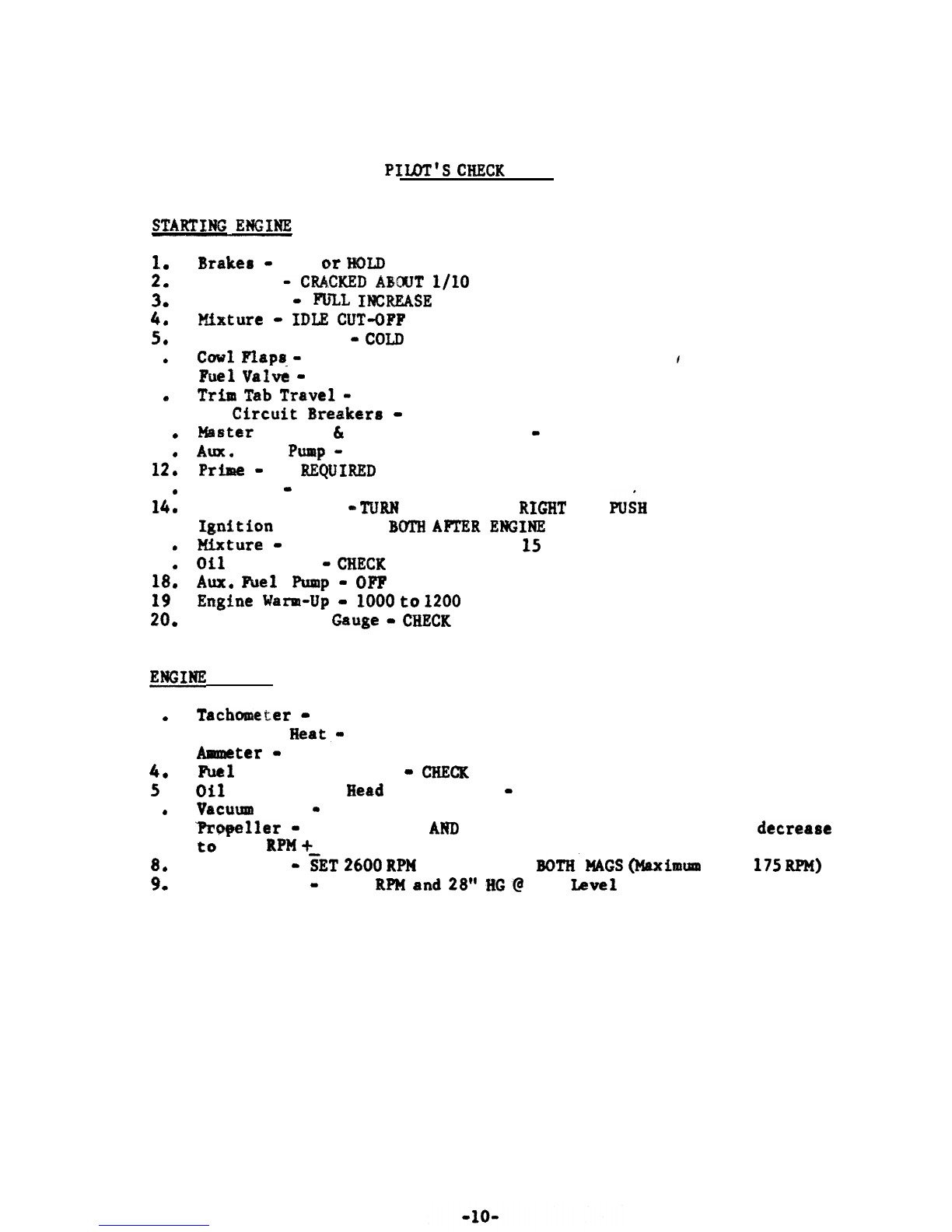
PSulrr’S
CEECIC
LIST
1
a
2
*
3
a
4
8
5
*
6
*
7
a
8
6
9
l
10
0
11
0
12
0
13
0
14
0
15
a
16
8
17
0
18
a
19
l
20
*
Brakere
=
SET
(zr
HDLD
Throttle
CKElD
AHXJT
l/IO
Propeller
-
FIsE;lL
INcIbEASE
l9fxture
-
IDLE
CUT-OPF
Carburetor Heat
-
Cow)
Cuwl
Fhps
-
OPEN
ptpel
VaPv6
-
ON
Trim
Tab
Trs.vel
-
CHECK
All
Cfrcuit
Breakera
-
IN
Master
Battery
br
Generator Switches
-
ON
AUK.
Fuel
Ptupap
-
ON
Pl?h
-
AS
EtEQUlRED
Propeller
-
CLEAR
Ignition Switch
-
TURH
TO EXTREME
RPG)IT
AND
P&H
Ignition
Switch
-TO
BOTH
AFTERENGINE
STARTS
Mxture
-
RICH
(Simultaneously
with
15
above)
Oil
Pressure
-
CHECK
AWL
IPfxel
Pump
-
Ol?F
Ermghe
Wism-Up
-
1000
to
1200
RPM
Fuel Quantity
Gauge
II*
CEECK
fNGINE
RUN-UP
1
a
Taslchmcter
-
SET 1500 to 1700 RPM
2
a
Carburetor
&at,
-
HOT THEN COLD
3
a
ter
-
CHECK
4
*
he1
and Oil Pressure
-
c%fxcIR
5
l
8il
and Cylinder
Head
Temperature
-
CHECK
6
a
Vaculam
Gauge
-
CHECK
7
l
3kwq?eller
-
SET
2200 RPM
AI!tD
EXERCISE SEVERAL TIMES
(Should
decrease
ta’
1275
RPM
+50 RPM)
8
*
Propeller
-
iii3T
2600
RPN
AND CHECK
BOTH.
M&S
OiLpximm
drop
175
RPM)
9
*
Power
Check
-
3400
RPM
an8
28"
.$iG'@
Sea
Imrel

1
4
2
4
3
*
4
l
5
4
6
4
7l
0
4
9
0
10
0
11
4
Flight Controls
-
FREE,
FULLTRAWL
Flight
Instrtmmts
=
SET
Ehgine
Instruments
-
CHECKED
Trim Tab
-
SET
wing
Flaps
-
20 to
30
DEGREES
AS; DESIRED
Propa
f
hr
-
FULL
IHXEASE
RPM
Mixture
-
RICH
Carbe
Air
-
COLD
Cowl
Fup(I
-
OPEN
Seat
md
Shoulder Straps
-
TIGRTEN
Awr.
Fuel
Pump
-
ON
TAKI&-OFF
1
l
!Fhtottle
-
FULL
APtD
TXGHTEN
FRSCTXON
NUT
2
I,
Puwer
Reduction
-
A
R LIFT OFF FULL
THROTTLE
AND
IXXE
TO
30004kPM~
AIRSPEED
80
MPH
MAXLMJM
3
4
Fl
aprs
-
RAISE
4
l
Aux.
he1
Pimp
-
OFF
5
l
Cylinder
Head
Temp.
-
CHECK
(AIRSPEED
-
CLIMB
90
MPH)
6
4
Cruf.se
Cl%mb
-
WLL
THIKJTTLE
AND
2750
RI=
1
4
Thruttle
-
23”
??Gc,
M.P.
2
0
Propeller-
2600
RPM
3
4
Cowl
Flaps
-
AS
REQUIRED
1
*
Seat
8elts
-
TIGHTEN
2
4
carburetor
Heat
-
CfoLD
(EXCEPT IN
XCIms)
3
4
Mixture
G
RICH
4
l
Propeller
*
3000 RPM
5
4
Awe.
Fuel
Pump
-ON
6
0
Wing
Flapr
-
AS DESIRED
7
4
Propeller
-
FULL
ZYCREASE
ON FINAL APPROACH
1
4
Cowl
Flaps
-OPEN
2
4
Wing
Flaps
-
UP
3
4
A*.:-heI
Pump
-
OFF
4
0
Electricrl Switches
-
UNNECESSARY
SWISHES
OF?
I
4
Cylinder
Head
Temp.
-
CooL
(3SOop
or
LESS)
2
0
Throttle
a
1000
RPM
3
0
Propeller
-
FULL
mw
PXTICH
4
4
Mixture
-
XDLE
CUT-OFF
5
l
All Switches
-
OFF
IMPOR’EMT
NOTE:
It
fr
atrongls
reccmmndcd that
cl1
pilots become thoroughly
familbm with the
techntques
outlined
in
the
Omorr
Mstausl
before
operrtiqg
thirs;
aircraft
in full-flapped
STOL
rlaw-flight.
a
11
a

PILOT%
EMERGENCY
CHECK
LIST
1
0
Abort if
BEmRE
Airborne
8. Throttle
-
Clased
b
l
Control Wheel
-
Back
C.
Wheel
Brakes
-
Apply
d
l
*Propeller
-
Full
aaicreaae
RPM
e.
Mrture
-
Idle
‘Cut-off
f
l
*Fuel
ScPe;ctor
v&?e
-
Off
8
l
*Ignition
Switch
and
Master
Switch
-
Off
h
l
%rixq
Aircraft to Stop and Inveatigatc
t
2
*
Abort AFTER
kcasrrfng
Airbo+ne
8.
If bchw
50
feet
-
Hold
Yoke
Back
b
*
If
above
SO
feet
-
Hose over
artd
attampt
to pick up approximately
65
ME%
to facilitate a normal
ImHag
flare-out with flaps
down.
Wheu
flapa
are Up
-
Glide
at
80
KPH,
for
6eat
glfde
distance, If
time
perlarite,
luwer
flaps, glide at 65
MPH
and make
Normal
Landing.
c..
Throttfe
-
Cloud
d
l
Mixture -Idle Cut-Off
ENGINE
FAIUJRZ
OR
FIB*
DURING FLIGHT
1
0
Throttl+
-
‘Closhd
-
2
0
*PrqMBller
-
Full Decrease
RPM
(OUT)
3
l
Maxfmm
Glide
Di8tsnce
Airbpted
-
Attain
80
MEW,
IAS
with flaps up.
USC
the
txces~
in
aimpeed
0-r
80
W%
to
attain
altitude,
if desired,
4
l
mixture
-
Idle
Cut-Off
5
l
*Fuel
Selectors
-
Off
6
l
*Zgnition Switch
-
Off
7
l
mdio
Call
=
Acampliah
8
*
Flaps
-
As
Required
9
e
Generatar
Switch
-
Off
10
l
mater
Switch
-
Off
PROPELLER
FAIUJIXE
IN
FLIGET
1
lPropeller Overspeed
a.
Throttle
-
Retard
b
8
Airspeed
-
Reduce
c.
Propeller
-
Attempt
to
decrcgst
RpMt
with Propeller Control
d
0
If propeller govemmr regains
control,
maintain
2500
RPM
and
70
HP&
IAS
and lend at
mearercrt
airfield.
If net, use
an
hitucie,
airqmed
and
power
cmbination
to
attempt to
beep the
RPM
below 3400.
land
rt
nearerrt
landing
area.
2
b
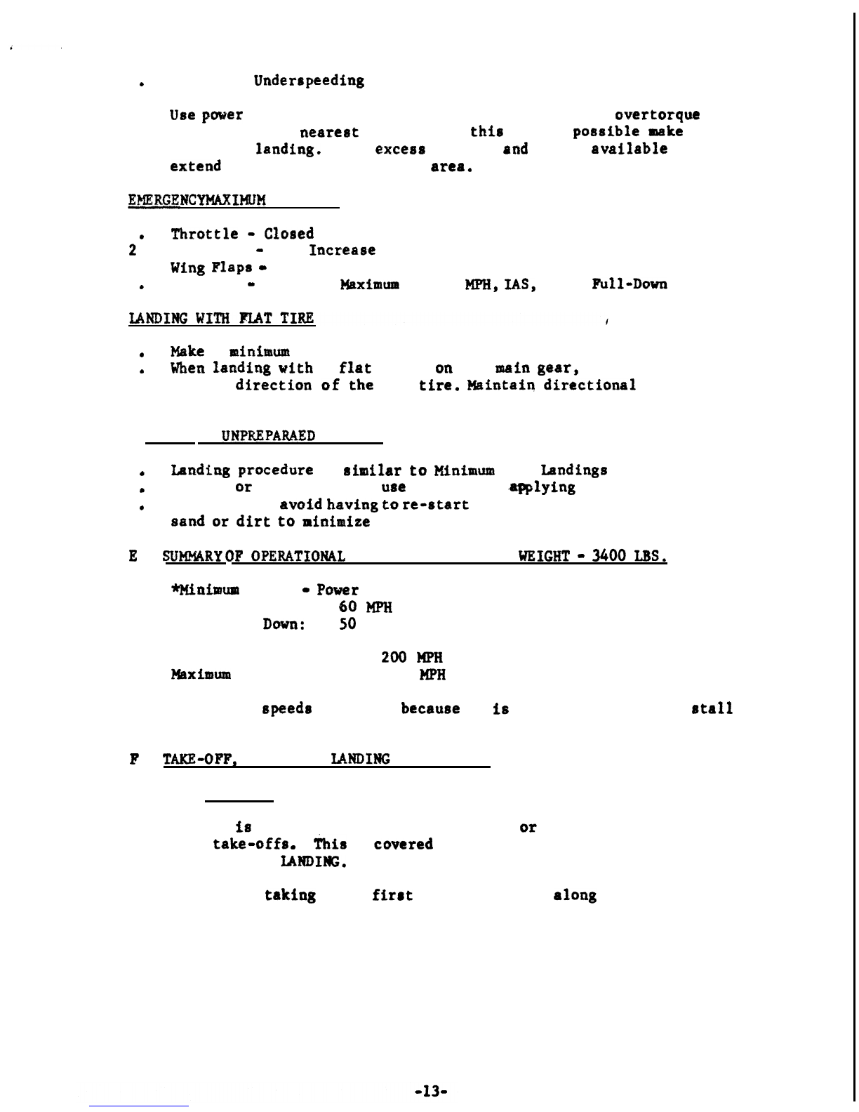
Propeller
Underrpeeding
Use
power
enough to maintain altitude without engine
overtorque
and proceed to nesrest airport, If
this
is not
pcralrfble
mka
emergency
landin& Use
excem
altitude
otnd
power
available
to
extend
glide to best available
area*
EmRGENCY
MkXIMj#
DESCENT
1
0
Throttle
-
Cleaard
2
l
Propeller
-
Full Iacrease RPM
3
l
Wing
Flaps
-
Full Down
4
&
Airspeed
-
Maintain
Maximum
of 80
MPH,
IAS,
Flaps
Full-Down
1
0
Make
a
8ai~iiwm
safe-epaed touch-down,
2
a
Wtren
landing
with
8
flat
tire
OR
the
msain
g8ar, the aircraft will turn
in the
direction
of
the
flat
tire.
mfntaiq
directfmal
control
with the rudder and brakes,
LANDING ON
U#P&EPARAED
TERRAIN
.
1
*
Xaudiug
pracedure
is
arfsaflar
to
Hlnimm
Run
Lmdings
(Full STOL)
2
*
On soft
or
rough ground,
use
caution in
.-lying
brakes.
3
*
If possible,
avoId
having
ts
re-start
and
rev-up
engine in
loose
sand
or
dirt
to
niaimize
propeller damage,
E
l
SUMRY
OF
QPERATXONAL
AIRSPEEDS AT GROSS
WXGHT
-
3rboo
LBS,
Mnimum
Speed
-
Paver
Off
Flaps Up:
60
MPH
I.A.S.
Flaps
lh?wu: 50
MPH I.A.S.
Never Exceed Speed:
200
MPH
I.A.S.
I$mimuma
Flap Speed: 80
MPH
I.A.S.
*Minimum
speeds
are given
because
it
fs
not possible to fully
stall
the
airplane
l
P
l
TAICGOFF,
CRUISE AND
lANDIlVG
TECHNIQUES
1
l Take-Off
It
fs
suggested that 30 degree flaps
or
less be used for all
take-offs
m
This
is
cmmred
in greater detail under STOL TAKE-
OFF
AND
LANDIMG.
When
taking
off,
firrt
align the aircraft
alang
the
intended
take-off track,
Release brakes and apply power
smoothly,
As
aircraft
accelerates apply Blight back pressure
m
cantrol
whee
1 l
When an
atirapetsd
of
approxiwaely
40
MFH
has been reached
the
awe
~hcel
will
rutrmte
and the aircraft will
bet-
aPrborne.
When
afrborae,
reEeasc
some
bmlc
pressure and
aTlw
tbe sirepeed to
bncrasse
to 64
Ki?it.
while
continuing
tu
climb
at
64
XI?‘&
reduca to
3000 RPM
and
mahmia
full
throttlr!
(5
slim&es
at
t&x!-off
WM
of
3400
and full throttle ia
permited),
Flaps may
remain
at
3Q”
and an
airspeed
of
64
MPH
used for
berrrt
rate
of
climb,
or until
cltaax
or
abatruct&ona.
when
opmIRting
fmm
8
clmw ama with
‘ITO
o’tbIrtruct$ons,
flaps my be raised, slowly
to
preveat
lev~baff
or settling, and
allsw
the air-speed to
fncrease
to 90
MP??
for best
rrate
of climb.
The
RI?M
may
be reduced again
ta
2750
and
full
throttle for
ellmb-out
to
insure
deqcmte
engfne
cool-
ing due td enriching
fmturer
of the carburetor,
Check
fuet
pseeaure
and
turn
off fuel
boost-pump,
Re-adjust
cowl
flaps
aa
raqutired
e
Mmhwm
penaiasibla cpIinder head
temperature
is
475*
for climb
and
450*
fur cruise.
Mast
new
pilots
to
the Currier tend to
over
rutate
on
take-off,
Due to
the
hLgh
lift of the
wfng
md
the large area of the all-
movable
hsriosuntal
tall,
it Es posafblc to
assume
an
excessive
mm
high attitude
when
making
a
short ‘field
takewff.
HCW@V~r,
the
mew
pilot quickly
hams
from experience
how
soon
the aircraft
rssy
be lifted off.
2
a
Cruise
Fl
ight
Tktottle
-
Set {Approximately 23”
HG)
PropelZer
*Set at 2600
Rm
Cawl
Flicpa
=
As Required
Carburetor
Heat
-
As
&q&&d..
The above cruirre
pwer
setting
isr
considered a good average
settfag
for
cross~country
flighta,
Cruise
power
settings can be determined
from
the appropriate engine
power schedule
charts
found in the
Lpcrrrafag
Operators
Pfamml.
No
Mmual
lesning of the
ntfxturc
fs
permitted. The
AMC
(Automatic
Mixture
Control)
ccmymmatts
fur
altitude
and
temperature changer.
3
a
Pmmr-Off
mad
Powm-On
Landing@
Since
the Courier,
In
the
20
degree
flap
(half-flap) configuration,
has csnventimal
or
normal landing
eharrctsriatics,
it
$8
apptapriate
to
rstart
out
on
half-flap landings during the first hour of
familiari-
tation,
Even
though
the
Cuurier,
with half-flaps, handles
liks
other
coavlenttaaal
aircraft,
it
rtill
hrs out-standing
ahurt
field
ckrracttr-
irtics.
For half-flap landings,
an
approach speed of
65
to 70 miles an
hour
its
~~llp
desirable
when
irastrectiag
a pilot
new
tu
the
Courier
l
As the pilot’s
profSciency
ihcreascls,
approcrch
speeds
wf,th
half-flaps
can
be reduced to 66
MI%,
though use
af
mxm
pmmx
then
becms
ctdvtsable.
When
appstaaehfag
for lauding at
this
speed, the pilot should be
rmitided
that the
darts
will pop
out
just
8s
ha
begins
his
flare-out
and
that
they will
have
nc)
effect
upon
the
control-sbititp
or
balance
of
the
aircraft.
With
half-flaps
at
60
MPH,
however,
the
acitcxaft
has little
@@floatVQ
and
should be
flared
or
rotated out fairly-close to the
ground
sc)
that it will
nut
develop
tcm
much
rate-of-sink before
touching
dawn.
Fur
fu31-flap
landinga
the, best
technique
fcm
aXowing
the
air-
craft
down
in the
ap~romh
is
first to
extend the
f&alps
to
20°
startfag
it
80
MPH
or
less, Then, when aircraft has
s2uwed
to
about
65
MPIi
ta
half-flap condition, the
flaps
can then be
brought
into
fulI-dmm
position and
a
landtag
made
by touching
down
on
thet
main gear first at
~rrini.sm.sm
airspeed,
Qne
approach to the full-flap landing ts
tib
have the pilot pop
out the slats by
slowing
the
afrcraft
down
to
5f)
?%PR
acfrile
still
wweral
hundred feet in the
sir.
and then to
compcnsstc
for the
incaeased
rate-of-sink
by
maintaining
partial power until
touch-
d-n.
As we proceed to the
fullmflap
landings, it is well to realize the
fact
that
when the lift of
any
normal
wfng
is doubled by the
USC
of
a flap, the drag
is
increased
Buzr-fold.
This
high
drag at the
full-flap pssitfun
nm
only
producelr
a very steep
rate-ofmdescent
but
also
mearm
that
the
aircraft will have very
litt*‘flcmt*@
once
ths nose
Is
raised for flare-aut, Consequently,
%n
a
full-
ftap
no
puwer
landing,
the
ccirctaft
should
be
held in a nose-
dmm
glide until about ten
feet
fram
the
grotui&if
the
gliding
speed is
higher
or
lower,
the
altitude
for beginning the
flare-
out
can be higher or
lower
accordingly.
As
an
examplt,
if the aircraft
i8
lmmght
in at the relatively
ccmfmtable
gliding
aped
of 60
?%I%
power off and a flare out
is begun at
the
eustammy
approximate thirty-feet above
the
terrain, speed will be
lost
very rapidly and
a
high
rate-of-aink
ccmld
develop,
The
resulting impact could be quite hard.
No.
matter
huw
high the pilot levels out, the
autcmatfc
slats eliminate
all risk of tolling off into an uncontrolled stall
or
spfa,
al-
though high rates of
deocent
can
occur if insufftcLent
power
is
used
m
The best technique for full-flap
landiws
fftvolves
the
maintenance
of
a Xfttle ~cmer-on, just
sufficfent
tt=o
offset the added drag of the
flaps and to produce a relatively
normal
glide
mgle.
This
is
done
by
maintafnfag approximately ten to
flfteca
inches manifold
pressure,
depending upon the load
md
air conditfoa. The aircraft is then
flared out and
land&d
in a
cunventionaf
manner,
much
the
sm
as with
half-flaps,
The
approach
speed,
however, is
closer
to
50
M%
than to
6Om1
.
When
win&the
lower
aped
Irficiing
tzue,
the throt!fQ should
sot
be
cztsaed
camplletely
until
wheirlts
ma
grounds
at
wMeh
tfme
tlw
poke
ahuuld
be
hald
full
beck.
An
advcrntage
of the partial
power
approach is
eae,se
of glide path
cuntrol
by slight imxeases or reductiom in the amount of
pamr.
The
full-flap
no”~~“wer
landing,
while
not
difficult, fe usually
desirable
only
as
an.
emergency procedure,
Inatrucdon
in this
type of landing is
laeceasary,
In order to make
amooth
landings,
it
iavolves
a
different te&nique with which
Ccmrier
pilato
rahcmld
be famiI.iar. For
ful,I-flap,
no-pop~rer
Landingr,
it
is
advisable that the
pflot
keep
the
aipproach
*peed
st
60 to 65
MPH,
but not
below
60
WEi.
miatain
arpproach
speed of 60 to 63 MPH
=ii-&ec~f~s
just off
the
rummy,
With power-off, the
flare
out
ahould
not
be ataxted tm3.l
wfthfn
10
to
Z3
feet off
the ground mthat the
n6se:
barely
ecmm
up to the full landing
positfsa
just
as
the
sircxaft
sinks
dowa
to
gmuad
level.
whfch
is
a
safety feature for emergency
or
forced
land$.ngs,
Consequently,
a
stfghtly
high flare-out will quickly
re8uft
in
a
xelcrtfvely
high rate of descent,
Le,
j
a hard landing!
:
Use
of
full-flape
without
.puwer
iar
nomally
done
ocrly
in
emelpgency
landings
s
Normal
SIXJL
approaches with full-flap8
are
best
accomplighed
with
part&al
power
so
a~
to
xmintaia
tssentially
the
mme
flight-psth’arrgle
at about 55 MPH
as
results from 70
MPH
at
half-flaps and ao
puww,
The throttle
thenmtts
the
approcrch
control device.
4
e
STOL Take-0f.f and
Landings
The shortest ground run take-off under
aandetrd
conditbons
at
3000
Iba,
or
less can usually be accomplished with full-flaps,
Le.
4o”*
(This
W.11
nut,
howmmr
s
provfde
the
beslt
angle
of
clkab
if barrier clearance
fs
the objective,) The use of
3am
or
less, depending on load
and
prerraure
gltltude,
is
reammended
for
take-off.
Align aircraft
along
intended take-off track, Apply full power
in a steady
mannetr.
Do not
*@japP”
throttle
farward
l Release
brake
aa
power
is
applied,
Holding
brakes
on
while
full
povclr
is
being
applied is
not
necessary, or desirable. Keep aircraft
strafght
ontrack by
wing
rudder.
Try
to avoid
application of
the foot
brakes
unless
requfred
tu
matntaifn
dire,ctiemal
cantrol,
At
approxiastrtcIy
35
MPH, apply back
pressure on the yoke in
a
positive
manner
but
nut
LIU
fast
that
the aircraft ~QIS~S an
excessive mse high
attjttude
after lift-off. When the aircraft
breaks
ground j
ullar
it
to
remain
just above
the ground for
apprmctitcly
2 or 3
aecsnds,
so
that the
airaped
will build
up to over
SO
KFH
before
the airplane
rtarts
full-climb-out.
EstabZirrh
a
climb-out speed
af
SO
to 64
&SPH
as
SQQ~
aa
prmtical,
I
16-
Experience
galned
En
th%s
type
sf
take-off
w%ll
ermbh
the pilot
to determine
tha
aunt of yoke
mcw~mernt
and/or
rapidity of action
neceaaary
to get the
aircraft
airboxme
with
the
rpinimtm
of
gxourtd
run.
This type
.of
s~inimum
run
take-off
is
most useful when the
ground is rough, bumpy, muddy
ok
where
very
ICYW
obsrmles,
meh
us
hedgea
fmcerr,
dmzhes, etc.
are
present
r,
a.
Muddy
Terrain
Take-Off
*
The
Helllo
Courier
is
an
unusua1lp
good
“Blludder”.
A
modmately
muddy
field
ummlly
pre~cnta
no
problem;-
At
normal
pxassurt
altftudt
am?
with
loctds
of
3000
lbs,,
or
lbss,
fulll?flaps
ace
usually
nm-xe
advantageous
fn
breaking
free
from
clfngfng
mud.
The following
procc?dure
ie
rec~nded:
Apply
full
power,
(Da
raat
bald
pa~~-on
SO
Pang
am
to
ovlerhest
the
engixw
if tha aircraft
faire
te
move,)
HoId
poke
fur2
.back
then
rock
poke
abruptly, usiag
full, but not proloaged,
fmmrd
positfon,
to
help
break the
wheels
free!
(,
When
the
aLrmaft
begkns
to
mmm,
the
oscflIatfag:
mmmmmms
of
the
stabffator
athould
be reduced mthat
there
is
equal **float-
atiun” on all
three
wheels
as
the aircrrrf
nmves
fortim+.
Then,
when
rolling free,
use
esaentfallp
the
mme
te
hnique
far the
mtnimum
run
take-off. Since
the
consistency
and
effect
of
diffwetlt
types
and
depth8
aX
wd
vmy
grbi?
y,
nu
stngle
rule
or technique can
substitute
for
expcr%ence
aad jud
nkt:
cm
soft and
irrreguXar
field
surfaces,
A muddy landing
or
deep
smw
landing
cmz
u.sualXy
best be mde by
using
full-flaps and plrscfw the
aircraft
onto the
groutrb
iu a
slight nom-high position
st.minismm
speed,
Acttmlly
touching
the
fn
wheels
firat
may
bc
adwmmgeous,
but the
mm
should not be
allowed
to
slam
dawn
into
the
mud.
After the
mime-wheel
touch-duwn
take
rll
power
off
and hold
poke
fully back.
If
fcmard
speed is
thus
held
low
cTn
the
touchdown, it will
tend
to
prevmtt
mm-over.
(This
procedure is essentially the
ame
as that
coaerrtonly
rsccmmmded
for
ditching
in
water.)
Rough
ground
or other
condi.tEons
may be
a
datermfning
factor where,
iu spite of a barrier,
the
full-flap
minimm
ground
run
take-off
may be
neceauary.
It
should
be
re-emphmtzed
here
thrat
WG~
#hen
tryfng
to
climb
out
af
a
mall
mea
at
too low
u.
apeed
with
the
Helis
Cmrier,
there
is
no
danger
sf
stlllfag,
losing
lateral control,
or
gofag
iuta
a spin.
s!u~evar,
a
coaditfcm
can
develop,
aspectally
with
full-
flaps
dm,
whereby
ther
mme
ir
heId
taa
high
and the
Eapesd
too
tow
cafter
take-off,
So
that the
afrcraft
will
actually
loge
altitude
wLth
power
fall
ma.
The
asost
emoa
cause of HeIia
crsahe~
and major
daarage
-- though
nmmr
with
s~iatss
fnjuxy
to
occupants
--
has been
from
efforts to
pull the aircraft off the ground
prematurely
at
toa
law
B
speed
and/m
roactirr;ntly to try to
cltaab
aut
with
tao
low
an
airspeed
psith
flaps
dcwa
se
that the
remlting
high-drag
exceeda
the
re-
drtced
thrust
ef
the propeller
a;t
km
fmrvmrd
Bpeeds,
Thus, with
power full-on, the
rafrcr~ft
my
either
sink
?mck
ta
the
ground
or fail ta clear
otherwfiae
-joy-sasaaoontable
sbstactes.
It
takes considerable
expcricn~e
ta
rscogaize
the
point
at
which
I
the
nose
high attitude
starts to
reduce
the
rate-of-climb
aad
then
may
finally progmss
to
an
actual
rate-of+fnk
despite full power.
This condition is
often
referred
to
am
**the
back
side”*
af
the
thrust drag curve,
or
simply as
“the
back side
rof
the
mer
curve”.
Canstqueatlp,
a
**zocmw
after take-off
irr
order
to
clear
a cluse
barrier
should
be strictly
8~
cpergeiacy
ptocadure
fur
expcrfenced
Hcrli.0
pflots*
Climb-out
speeds
below
50 MPH
arc
nqt
recmmmdtd.
d
a
Sharcttst
Distance
Take-OffsOver
Barrier (Grass
Weight
3000Q
OF
Higher)
With
30
degree
flaps
alluw
the
aircraft to accelerate as quickly
818
pcmsible
to
40
KPH.
Wfth
the
airspeed
indicating at
feast
40
MPH,
fly the
ieircrsft
off by applying the
approprfPte
back
pxe8-
msre
on
the
elevator
until it is airborne,
Permit
the
sirsaecsd
to
build up
for
rpprcmimatalg
two
mxands
au
abaut
50
MPH,
then
begfn
rotation to the
point
that
will
climb
the
aircraft
over
the barrier
without
further build
up
of
airrpted.
After consfdtrable
txperi.mcel
ewea
shorter barrier
diatanee
can
be
attained
by
hoEding
the
aircraft
to
about
30
MPltI
&n
a smooth
ruuwuy
and
then
%omimg**
over
the
barrier
at an
amble
sufficiently
steep
to
clcrar
the barrier without
lass
of
airspeed
after
whfch the
~~cme
can
be
lowered
and
the
nmma
rate-of-climb airspeed
attaiaed.
Grcrt
skill
ia:
n6Ctssary,
hcnmmr,
ta
avoid
lass
of
speed and
consequent
Mweatrry sfaking
efthtr
just
before
or
just
after
craerslag
the
barrier,
Such technique
kr
not
rscmnmdcd
for
other
thaa
cmcrgency
tituutian&
18
Table of contents
Other Helio Aircraft manuals

Popular Aircraft manuals by other brands

GRAVITY
GRAVITY X duo manual

SOL paragliders
SOL paragliders SQUAD LIGHT owner's manual

Pipistrel
Pipistrel Virus 912 Flight and maintenance manual

Dancing Wings Hobby
Dancing Wings Hobby Savage Bobber instruction manual

Grob
Grob TWIN-ASTIR FLIGHT HANDBOOK

SOL paragliders
SOL paragliders ELLUS 2 Pilot's manual


