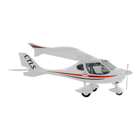
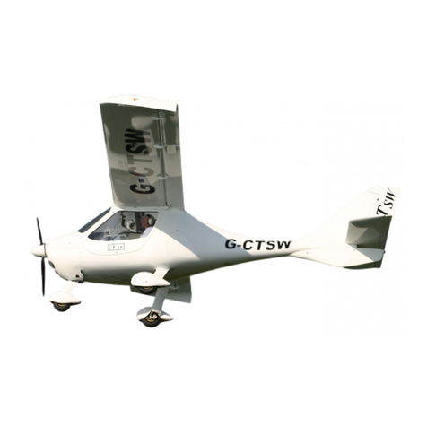
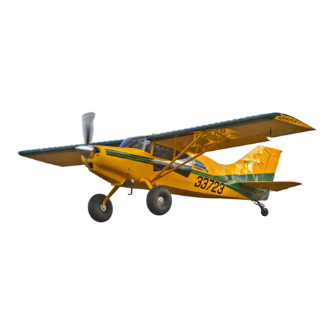
FLIGHT DESIGN CTLS LSA Series User manual

CTLS
LSA
SERIAL NUMBER:_______________
Aircraft Operating Instructions (AOI)
THIS DOCUMENT AND THE TECHNICAL DATA HEREON DISCLOSED ARE PROPRIETARY TO FLIGHT DESIGN AND SHALL NOT
BE USED, RELEASED, OR DISCLOSED IN WHOLE OR IN PART WITHOUT EXPRESS WRITTEN PERMISSION FROM FLIGHT
DESIGN

Aircraft Operating Instructions (AOI)
Type:
CT
Series:
CTLS
LSA Page: ii
AU 010 11000 Revision No. 6 Date: 05 Feb 2009
REVISION STATUS
Rev Pages Date Chapter completed
1 All Jan 08, 2008 All OR / TP
2 61 Mar 03, 2008 7.4.6 Carbon monoxide detector added
- System of pages numbering changed.
- Formatting (page breaks) partially changed
1-1 “All avionics and instruments recommendations
in this document is for reference only.” Added to
item 1.1
1-3 – 1-4 Continued airworthiness instructions added as
item 1.4
4-17 4.14 Autopilot control added
6-5 6.4 Equipment List updated
7-6 – 7-7 7.2.3 Fuel system updated
3
11-3
Apr 01, 2008
11.3 Safety of flight report form added
Vasyl Sys
4-7 4.5 Autopilot operation chapter moved from 4.14
to 4.5 and updated
4
7-7
Apr 29, 2008
Fuel system diagram corrected
Vasyl Sys
1-1 1.1 Warning re-formatted and reworded
1-2 1.2 Manufacturer address corrected (house no.)
2-1 2.1. stall speed flaps -12° added; note added
2-3 2.5 Idle engine speed corrected
7-26 7.5 green arc limits for flaps -12° case added
9-1 9. Chapter reworded
5
10-1
Jan 16 , 2009
10. Chapter reworded
Oliver Reinhardt
Completely revisionAll
Number of document changed. Numerical
consistency of revision is continue from previous
document – AU 010 11000 with 5 revision
2-1 Stall speed flaps -6° added; -12° - deleted
3-10 Flap’s positions and corresponding data were
changed
4-9 Flap’s position -12° deleted in the picture
4-10 Changed to -6° only
6
4-12
05 Feb 2009
Changed to -6° only
Alexandra
Lyashchenko

Aircraft Operating Instructions (AOI)
Type:
CT
Series:
CTLS
LSA Page: iii
AU 010 11000 Revision No. 7 Date: 07 May 2009
REVISION STATUS
Rev Pages Date Chapter Completed
4-15 Flap’s position -12° deleted
4-16 Flap’s position -12° deleted
7-16 Flap’s position -12° deleted
7-26 Flap’s position -12° deleted
7-27 Flap’s position -12° deleted
Flap’s position -12° deleted
6-1 –
6-10
Chapter 6 complete enhanced by weight and
balance chart; equipment chapter in contents
unchanged
3-6 3.6 – information updated to match Junkers
Magnum Rescue System
7
7-17 –
7-19
May 07, 2009
7.3.9 – Information updated to match Junkers
Magnum Rescue System
Attitude angle corrected to 13°
4th belt added in illustration with deployed
system
Oliver Reinhardt

Aircraft Operating Instructions (AOI)
Type:
CT
Series:
CTLS
LSA Page: iv
AU 010 11000 Revision No. 7 Date: 07 May 2009
LIST OF EFFECTIVE PAGES
CHAPTER CHAPTER CHAPTER CHAPTER
PAGES PAGES PAGES PAGES
REV REV REV REV
1-1 5 4-8 4 6-9 6 8-1 4
1-2 5 4-9 6 6
(cont.) 6-10 6 8-2 4
1-3 4 4-10 6 7-1 4 8-3 4
1-4 4 4-11 4 7-2 4 8-4 4
1-5 4 4-12 6 7-3 4 8-5 4
1-6 4 4-13 6 7-4 4 8-6 4
1
1-7 4 4-14 4 7-5 4
8
8-7 4
2-1 6 4-15 6 7-6 4 9 9-1 5
2-2 4 4-16 6 7-7 4 10 10-1 5
2-3 5
4
(cont.)
4-17 4 7-8 4 11-1 4
2
2-4 4 5-1 4 7-9 4 11-2 4
3-1 4 5-2 4 7-10 4
11
11-3 4
3-2 4 5-3 4 7-11 4
3-3 4 5-4 4 7-12 4
3-4 4 5-5 4 7-13 4
3-5 4 5-6 4 7-14 4
3-6 7 5-7 4 7-15 4
3-7 4 5-8 4 7-16 6
3-8 4 5-9 4 7-17 7
3-9 4 5-10 4 7-18 7
3-10 4
5
5-11 4 7-19 7
3
3-11 4 6-1 6 7-20 4
4-1 4 6-2 4 7-21 4
4-2 4 6-3 4 7-22 4
4-3 4 6-4 6 7-23 4
4-4 4 6-5 6 7-24 4
4-5 4 6-6 6 7-25 4
4-6 4 6-7 6 7-26 6
4
4-7 4
6
6-8 6
7
7-27 6

Aircraft Operating Instructions (AOI)
Type:
CT
Series:
CTLS
LSA Page: v
AU 010 11000 Revision No. 6 Date: 05 Feb 2009
TABLE OF CONTENTS
1. GENERAL................................................................................................................................................ 1-1
1.1. INTRODUCTION.................................................................................................................................. 1-1
1.2. MANUFACTURER:.............................................................................................................................. 1-2
1.3. IN THE USA CONTACT ...................................................................................................................... 1-2
1.4. CONTINUED AIRWORTHINESS INSTRUCTIONS.................................................................................. 1-3
1.5. THREE VIEW,MAIN DIMENSIONS:...................................................................................................... 1-5
1.6. ENGINE ............................................................................................................................................. 1-6
1.7. PROPELLER....................................................................................................................................... 1-6
1.8. MINIMUM EQUIPMENT ....................................................................................................................... 1-7
1.9. RECOMMENDED ADDITIONAL EQUIPMENT ........................................................................................ 1-7
2. LIMITATIONS.......................................................................................................................................... 2-1
2.1. AIRSPEED LIMITATIONS..................................................................................................................... 2-1
2.2. FLIGHT LOAD FACTOR LIMITS............................................................................................................ 2-2
2.3. TIRE PRESSURE................................................................................................................................2-2
2.4. MASS AND CENTER OF GRAVITY LIMITS:........................................................................................... 2-2
2.5. POWER PLANT LIMITATIONS.............................................................................................................. 2-3
2.6. OTHER LIMITATIONS.......................................................................................................................... 2-4
3. EMERGENCY PROCEDURES............................................................................................................. 3-1
3.1. EMERGENCY PROCEDURES CHECKLISTS ......................................................................................... 3-1
3.2. STALLS.............................................................................................................................................. 3-3
3.3. INADVERTENT SPIN ........................................................................................................................... 3-3
3.4. EMERGENCY LANDING ...................................................................................................................... 3-4
3.5. AFTER OVERTURN ON LANDING........................................................................................................ 3-5
3.6. DEPLOYING THE BALLISTIC RECOVERY SYSTEM............................................................................... 3-6
3.7. ENGINE FAILURE............................................................................................................................... 3-7
3.8. CARBURETOR OR ENGINE FIRE......................................................................................................... 3-8
3.9. LOSS OF COOLANT............................................................................................................................ 3-9
3.10. LOSS OF OIL...................................................................................................................................... 3-9
3.11. FAILURE OF FLAP CONTROL............................................................................................................ 3-10
3.12. DYNON EMS FAILURE (IF INSTALLED)............................................................................................ 3-11
4. NORMAL PROCEDURES..................................................................................................................... 4-1
4.1. NORMAL PROCEDURES CHECKLISTS................................................................................................ 4-1
4.2. PREFLIGHT INSPECTION.................................................................................................................... 4-5
4.3. PASSENGER BRIEFING...................................................................................................................... 4-6
4.4. STARTING THE ENGINE ..................................................................................................................... 4-7
4.5. AUTOPILOT OPERATION.................................................................................................................... 4-7
4.6. BEFORE TAKE-OFF............................................................................................................................ 4-8
4.7. TYPICAL PATTERN............................................................................................................................. 4-8
4.8. TAKE-OFF AND CLIMB...................................................................................................................... 4-11
4.9. CRUISE............................................................................................................................................ 4-13
4.10. TURNS............................................................................................................................................. 4-14
4.11. STALL.............................................................................................................................................. 4-15
4.12. APPROACH AND LANDING ............................................................................................................... 4-15
4.13. SHUTTING DOWN THE ENGINE ........................................................................................................ 4-17
4.14. CHECKING THE EMERGENCY LOCATION TRANSMITTER (ELT)....................................................... 4-17
5. PERFORMANCE .................................................................................................................................... 5-1
5.1. PERFORMANCE DATA FOR MTOW @600 KG (1320 LBS)............................................................. 5-1
5.2. FLIGHT ALTITUDE AND DENSITY ALTITUDE........................................................................................ 5-2
5.3. SIGNIFICANCE OF THE WIND COMPONENT........................................................................................ 5-4

Aircraft Operating Instructions (AOI)
Type:
CT
Series:
CTLS
LSA Page: vi
AU 010 11000 Revision No. 6 Date: 05 Feb 2009
5.4. ENGINE PERFORMANCE SUBJECT TO ALTITUDE............................................................................... 5-6
5.5. CALCULATING THE TAKE-OFF DISTANCE .......................................................................................... 5-7
5.6. CALCULATING CLIMB PERFORMANCE ............................................................................................. 5-10
5.7. GLIDING CHARACTERISTICS............................................................................................................ 5-11
6. WEIGHT AND BALANCE, EQUIPMENT............................................................................................ 6-1
6.1. WEIGHT LIMITS................................................................................................................................. 6-1
6.2. WEIGHING......................................................................................................................................... 6-1
6.3. FLIGHT MASS AND CENTER OF GRAVITY......................................................................................... 6-4
6.4. EQUIPMENT....................................................................................................................................... 6-9
7. AIRPLANE AND SYSTEMS DESCRIPTION..................................................................................... 7-1
7.1. AIRFRAME ......................................................................................................................................... 7-1
7.2. SYSTEMS .......................................................................................................................................... 7-4
7.3. FLIGHT CONTROLS.......................................................................................................................... 7-12
7.4. COCKPIT ......................................................................................................................................... 7-20
7.5. PLACARDS AND MARKINGS............................................................................................................. 7-26
8. HANDLING, SERVICE, MAINTENANCE ........................................................................................... 8-1
8.1. JACKING............................................................................................................................................ 8-1
8.2. SECURING THE AIRCRAFT FOR ROAD TRANSPORTATION ................................................................. 8-2
8.3. PARACHUTE RECOVERY SYSTEM MAINTENANCE.............................................................................. 8-2
8.4. CLEANING AND CARE........................................................................................................................ 8-3
8.5. MANDATORY AIRCRAFT INSPECTIONS .............................................................................................. 8-5
8.6. REPAIRS TO THE AIRFRAME.............................................................................................................. 8-6
8.7. CONTROL SURFACE DEFLECTIONS................................................................................................... 8-7
9. SAILPLANE TOW................................................................................................................................... 9-1
10. BANNER TOW ................................................................................................................................. 10-1
11. APPENDICES................................................................................................................................... 11-1
11.1. CURRENT WEIGHING REPORT.............................................................................................. 11-1
11.2. CURRENT EQUIPMENT LIST................................................................................................... 11-2
11.3. SAFETY OF FLIGHT REPORT FORM..................................................................................... 11-3

Aircraft Operating Instructions (AOI)
Type:
CT
Series:
CTLS
LSA Page: 1-1
AU 010 11000 Revision No. 5 Date: 16 Jan 2009
1. GENERAL
1.1. Introduction
Every pilot must familiarize him/herself with the specific characteristics of each Light
Sport aircraft. This Aircraft Operating Handbook (AOI-POH) must be studied in detail
before the first flight is undertaken with the aircraft. The same applies to the
operating handbooks and manuals of the ballistic recovery system, the engine and all
other equipment installed in the aircraft, such as the Dynon EFIS / EMS, etc. All
avionics and instruments recommendations in this document is for reference only.
Engines of Light Sport aircraft are not Part 33 certified aviation engines. The flight
route must thus be chosen to ensure that an emergency landing after engine failure
can be undertaken without difficulty.
The CTLS may only be operated under visual flight rules (VFR). Due to the high
cruise speed and the great range, pilots may encounter meteorologically critical
weather conditions more often. Flying into IFR conditions without the necessary
training is extremely dangerous. As the pilot in command, you are responsible for the
safety of your passenger as well as for your own safety. You are also responsible for
the safety of uninvolved third parties. Avoiding dangerous situations is a pilot’s first
duty.
Warning: Use only alkali-free products when cleaning your composite aircraft. For
more information, refer to chapter 8 Handling, Service, Maintenance.

Aircraft Operating Instructions (AOI)
Type:
CT
Series:
CTLS
LSA Page: 1-2
AU 010 11000 Revision No. 5 Date: 16 Jan 2009
1.2. Manufacturer:
Flight Design GmbH
Sielminger Str. 51
70771 L.-Echterdingen
Germany
1.3. In the USA contact
Flight Design USA
P.O. Box 325
South Woodstock, CT. 06267
860-963-7272

Aircraft Operating Instructions (AOI)
Type:
CT
Series:
CTLS
LSA Page: 1-3
AU 010 11000 Revision No. 4 Date: 29 Apr 2008
1.4. Continued Airworthiness Instructions
Unlike other aircraft for which the FAA is responsible for the continued certification
compliance, for Light Sport Aircraft, the burden of continued certification compliance
rests on a cooperative effort between the manufacturer and the Owner/Operator of
the aircraft. To this end, certain Manufacturer and Owner/Operator responsibilities
are outlined in ASTM F 2295, Standard Practice for Continued Operational Safety
Monitoring of a Light Sport Aircraft.
1.4.1. Manufacturer Responsibilities
In order to fulfill the manufacturer’s responsibilities, Flight Design USA maintains an
Operational Safety Monitoring System that provides for the following practices:
A. Operational Safety Monitoring, a system by which:
1. Safety of Flight and Service Difficulties are reported by the Owner/Operator.
2. Safety of Flight and Service Difficulty issues are received, tracked, and evaluated
by Flight Design USA.
B. Continued Airworthiness Support, a system by which:
1. Flight Design USA issues Safety Directives (Notices of Corrective Action) directed
towards correcting Safety of Flight and Service Difficulty issues.
2. The Owner/Operator obtains and verifies that they have the latest safety of flight
information developed by the manufacturer.
C. Maintenance Instructions
Provided to the Owner/Operator and pertaining to 100 hour and annual condition
inspections.
D. Continued Airworthiness Instructions
Provided to the Owner/Operator and pertaining to maintaining the certification
compliance of their S-LSA
1.4.2. Owner/Operator Responsibilities and Instructions
F 2295 states that the Owner/Operator shall:
A. Read and comply with the maintenance and continued airworthiness information
and instructions provided by the manufacturer.
These instructions are included in the Aircraft Operating Instructions, Maintenance
and Inspection Procedures and Flight Supplement manuals.
B. Provide the manufacturer with current contact information where the manufacturer
may send the Owner/Operator supplemental notification bulletins.
At the time of delivery, the Owner/Operator will provide the contact information to
Flight Design USA or its representative. Contact information may be updated at any
time by:
Writing to: Flight Design USA P.O. Box 325, South Woodstock, CT 06267

Aircraft Operating Instructions (AOI)
Type:
CT
Series:
CTLS
LSA Page: 1-4
AU 010 11000 Revision No. 4 Date: 29 Apr 2008
C. Notify the Manufacturer of any Safety of Flight issue or any significant Service
Difficulty issue upon discovery.
Safety of Flight report forms and Service Difficulty report forms can be found in the
aircraft manuals and on the Operational Safety Monitoring page of the
Flightdesignusa.com website
D. Comply with all manufacturer issued notices of corrective actions and for
complying with all applicable FAA regulations in regard to maintaining the
airworthiness of the LSA airplane.
Airworthiness information will be sent to the Owner/operator contact address of
record. Airworthiness information can also be obtained from Safety section of the
Flightdesignusa.com website.
E. The Owner/operator shall ensure that any needed corrective action be completed
as specified in a notice or by the next scheduled annual inspection.
Important: Should an Owner/Operator not comply with any mandatory service
requirement, the LSA shall be considered not in compliance with the
applicable ASTM Standards, and may be subject to regulatory action by
the FAA.

Aircraft Operating Instructions (AOI)
Type:
CT
Series:
CTLS
LSA Page: 1-5
AU 010 11000 Revision No. 4 Date: 29 Apr 2008
1.5. Three view, main dimensions:
Main Dimensions:
Wing span 8.60 m (28 ft 2 in.)
Length 6.61 m (21 ft 8 in.)
Wing area 9.98 sq. m (107.4 sq-ft)

Aircraft Operating Instructions (AOI)
Type:
CT
Series:
CTLS
LSA Page: 1-6
AU 010 11000 Revision No. 4 Date: 29 Apr 2008
1.6. Engine
The CTLS is only available with the Rotax 912 ULS with 100 rated BHP. More
detailed information on the engine is available from Rotax for your specific engine
serial number.
Engine type: horizontally opposed, four cylinder, four
stroke engine
Cooling: water-cooled cylinder heads
Horsepower rating and engine speed: 73.5 KW / 100 rated BHP at 5800 rpm
Carburetor type: Bing constant pressure carburetor
Ignition: electronically controlled dual ignition
Propeller gear reduction: 2.43 : 1
1.7. Propeller
Various types of propeller are available for the CTLS. Each propeller has its own
operating handbook and maintenance manual published by the propeller
manufacturer. These documents are delivered with the aircraft and must also be
studied in detail. The following types of propeller have been certified for the CTLS:
Neuform CR3-65-47-101.6, 3 blade, composite
propeller, adjustable
Neuform CR3-V-R2H, 1.70m diameter, 3 blade,
hydraulically activated variable pitch,
composite propeller
Kaspar- Brändel KA1, 1.60 m diameter, 3 blade, variable
pitch, composite propeller

Aircraft Operating Instructions (AOI)
Type:
CT
Series:
CTLS
LSA Page: 1-7
AU 010 11000 Revision No. 4 Date: 29 Apr 2008
1.8. Minimum equipment
Airspeed indicator up to at least 350 km/h (200 knots)
Altimeter with Barometric window
Safety harness four-point, one for each seat
Magnetic compass with calibration card
Engine instruments CHT, Oil Temp, Oil press, RPM.
Aircraft documents national regulations apply
1.9. Recommended additional equipment
Ballistic recovery system national regulations apply
Emergency locator transmitter (ELT) mandatory in some countries
Radio with intercom and headsets
Transponder Mode C or S
External lighting anti-collision light (ACL) and navigation
lights, landing light

Aircraft Operating Instructions (AOI)
Type:
CT
Series:
CTLS
LSA Page: 2-1
AU 010 11000 Revision No. 6 Date: 05 Jan 2009
2. LIMITATIONS
2.1. Airspeed limitations
Stall speed flaps -6° vs1 81 km/h 44 kts CAS**
flaps 0° vs1 75 km/h 42 kts CAS
flaps 35° vs0 65 km/h 39 kts CAS
Maneuvering speed va 184 km/h 98 kts CAS
Maximum flap extended speed flaps 0° vfe 184 km/h 100 kts CAS
flaps 15° vfe 148 km/h 80 kts CAS
flaps 30°, 35° vfe 115 km/h 62 kts CAS
Maximum rough-air speed vra 245 km/h 138 kts CAS
Caution range 245 – 269 km/h 138 - 145 kts CAS
Never-exceed speed (Vne) vne 269 km/h 145 kts CAS
* The never-exceed speed (VNE) demonstrated during flight testing is 301 km/h. However, VNE is limited by the maximum
deployment speed for the ballistic recovery system or national regulatory requirements.
** The maximum negative flap setting is limited dependent from the country where the aircraft is registered, due to
differences in national implementation of the LSA standards. So only one of the values for either -6° applies, dependent on
the individual aircraft setting.
Maximum demonstrated crosswind flaps 0° 30 km/h 16 kts
flaps 35° 20 km/h 11 kts
Warning: Take-off and landing with crosswinds require a lot of training and
experience. The greater the crosswind component, the more
experience required.

Aircraft Operating Instructions (AOI)
Type:
CT
Series:
CTLS
LSA Page: 2-2
AU 010 11000 Revision No. 4 Date: 29 Apr 2008
2.2. Flight load factor limits
Maximum flight load factor up to VA + 4g/ -2g
up to VNE + 4g/ -1.5g
Warning: Up to va= 184 km/h (99 kts) (maneuvering speed) full control
movements may be made.
Above vaall control surfaces may only be deflected to a third of their
maximum displacement.
Warning: Up to vra = 245 km/h (132 kts) IAS the CTLS can safely withstand a
vertical gust of 15m/s (3000 fpm)
Above vra = 245 km/h (132 kts) IAS the CTLS can withstand the load of
a vertical gust of 7.5 m/s (1500 fpm)
2.3. Tire pressure
Main landing gear tires 2 bar (28 psi)
Nose wheel tire 2 bar (28 psi)
2.4. Mass and center of gravity limits:
Minimum weight, solo pilot 54 kg (120 lbs)
Maximum mass per seat 118 kg (260 lbs)
Typical Empty weight, incl. recovery system *310 kg (730 lbs)
Maximum take-off weight (MTOW) 600 kg (1320 lbs)
Baggage compartment 25 kg** (55 lbs) maximum on each side
50 kg** (110 lbs) maximum in total
Center of gravity range 282 – 478 mm*** (11.1 inches – 18.8 inches)
* Nominal empty weight with minimum equipment. The true empty weight depends greatly upon the equipment installed. The
current weight of each aircraft is registered in the current weighing record. Refer to Chapter 6 “weight and Balance”.
** Maximum values. The correct values for each aircraft may be calculated from the current weighing record. Refer to
Chapter 6 “weight and Balance”.
*** Reference datum is the wing leading edge with the aircraft in the neutral position. Refer to Chapter 6 “weight and
Balance”.
Warning: The weight data given are standard values. The correct data for each
aircraft must be extracted from the current weighing record. Refer to
Chapter 6 “Weight and Balance”.

Aircraft Operating Instructions (AOI)
Type:
CT
Series:
CTLS
LSA Page: 2-3
AU 010 11000 Revision No. 5 Date: 16 Jan 2009
2.5. Power plant limitations
Maximum take-off power 73.5 kW (100 HP)
at 5800 rpm (max 5 min)
Maximum continuous power 69 kW (95 HP)
at 5500 rpm
Minimum take-off engine speed (fixed pitch propeller)
4800 rpm
Maximum continuous engine speed 5500 rpm
Idle engine speed approx. 1500 rpm
Cylinder head temperature, maximum * 120°C (248°F)
Oil temperature, minimum 50°C (120°F)
Oil temperature, maximum 140°C (248°F)
Recommended operating temperature 90 – 110°C (190°F - 230°F)
Oil pressure, normal operation 2.0 – 5.0 bar (29 – 73 psi)
Oil pressure, minimum 0.8 bar (12 psi)
Oil pressure, short-term maximum during extreme cold start conditions
7.0 bar (101 psi)
Oil grade brand automotive engine oils, no aviation
oil - refer to the relevant ROTAX operating
handbook for information on viscosity. Do
not use oil additives.
Oil tank capacity 2.0 - 3.0 l (2.1 – 3.1 quarts)
Oil consumption, maximum .06 l/h (.06 q/h)
Fuel tank capacity: 130 l (34 gals)
2 wing tanks with 65 l (17 gallons) each
Usable fuel: 128 l (32 gallons)
Type of fuel: Premium Automotive unleaded per ASTM D 4814
Minimum AKI 91. For more complete information
Refer to the Rotax 912ULS Operators manual. Or
AVGAS 100 LL.
* Coolant temperature is monitored via the cylinder head temperature which is measured at the measuring point of the
hottest cylinder
Warning: Due to its high lead content AVGAS has a detrimental effect on valve
seating and causes greater deposition in the combustion chamber. It
should thus only be used if fuel vapor or octane problems arise or if
MOGAS is not available.

Aircraft Operating Instructions (AOI)
Type:
CT
Series:
CTLS
LSA Page: 2-4
AU 010 11000 Revision No. 4 Date: 29 Apr 2008
Warning: When using AVGAS particular attention must be paid to type of oil
used. For details refer to the valid version of the ROTAX engine
manual.
Warning: The engine data given here is not complete. For complete information
refer to the current version of the relevant engine manual from the
Rotax company.
2.6. Other limitations
Warning: The aircraft is not certified for aerobatics!
The aircraft may only be operated during the day or night in visual flight conditions.
Flight into instrument meteorological conditions (IMC) is prohibited.
Flight into icing conditions is prohibited.
Turns steeper than 60 degrees of bank are prohibited.
Flight operations are not recommended during strong, gusty winds or wind speeds on
the ground of more than 46 km/h (24kts-30 mph).

Aircraft Operating Instructions (AOI)
Type:
CT
Series:
CTLS
LSA Page: 3-1
AU 010 11000 Revision No. 4 Date: 29 Apr 2008
3. EMERGENCY PROCEDURES
3.1. Emergency procedures checklists
Emergency procedures are initially presented in the form of checklists. Amplified
emergency procedures follow later in the chapter.
Even experienced pilots are strongly recommended to work with the checklists in the
cockpit. It is the only way to ensure that in the distraction during flight important items
are not overlooked.
The checklists are formulated so that they may be made into a small booklet which
can be used in the cockpit. This booklet can be augmented with specific operational
aspects should this be necessary.
The detailed procedures augment those points of the checklists which can only be
explained in detail. It is important for safe operation that the pilot familiarize himself
with these detailed procedures before starting flight operations.
Spinning
Controls neutral
Rudder opposite direction of
rotation
Rotation stopped
Throttle retard
Elevator smooth recovery from
dive
Deploying the ballistic recovery system
Ignition off
Recovery system release
Fuel shutoff valve off
Emergency radio call transmit
Master switch off
Safety harness tight
protective position taken
Engine failure
Below 300 Ft (100m) AGL make an emergency
landing straight ahead
Above 600 Ft (200m) AGL refer to procedures for
restarting the engine
Restarting the engine
Fuel shutoff valve open
Fuel amount check
Ignition both
Propeller stopped ignition key to start
Engine fails to restart make an emergency
landing
Emergency landing
No suitable landing field deploy recovery system
Landing field selected
Safety harness tight
Objects in cockpit securely stored
Emergency radio call transmit
Flaps as required
Airspeed as required
Flare 2’ (50 cm) above ground
or tree tops
Ignition during flare off
Fuel shutoff valve closed
Elevator on touchdown tail low
ELT automatic /
as required

Aircraft Operating Instructions (AOI)
Type:
CT
Series:
CTLS
LSA Page: 3-2
AU 010 11000 Revision No. 4 Date: 29 Apr 2008
Engine fire
Fuel shutoff valve off
Throttle full
Ignition off
Ignition key remove
Flight attitude slip away from flames
Landing make an emergency
landing
Loss of coolant
Engine power reduce
Cylinder head temperature below 150°C
Landing as soon as possible at
airfield
Loss of oil
Ignition off
Ignition key remove
Fuel shutoff valve off
Landing make an emergency
landing
Failure of flap control
Alternator off
Master switch off
Master switch after 3 seconds to on
Alternator on
If everything okay end of procedure
Flaps in cruise flight manually set to max.
negative
Long runway landing flap max.
negative
Short runway in short final, manually
set to max. positive
EMS failure
Reduce airspeed 100 knots (185 km/h)
with flaps negative

Aircraft Operating Instructions (AOI)
Type:
CT
Series:
CTLS
LSA Page: 3-3
AU 010 11000 Revision No. 4 Date: 29 Apr 2008
3.2. Stalls
The stall characteristics in level flight are docile. Normal flight attitude can be
recovered by pushing the stick forward, increasing speed and then smoothly pulling
the aircraft up again.
Maximum loss of altitude during stall recovery is 50m (165 ft). Pitch down does not
exceed 25°.
The aircraft does not go into a spin during a stall in a 30° turn. Normal flight attitude
can be recovered by pushing the stick forward, increasing speed and then smoothly
pulling the aircraft up and simultaneously correcting the angle of bank.
Maximum loss of altitude during recovery is 60 m (180 ft). The angle of bank does
not exceed 60°.
3.3. Inadvertent spin
The aircraft shows no inclination to go into an inadvertent spin during normal stall or
during stalls in turns.
Should the aircraft, however, inadvertently enter into a spin, the following recovery
procedure should be used:
All control surfaces in neutral position
Rudder opposite to direction of rotation
Retard throttle
Smooth recovery in the neutral attitude
Warning: As this aircraft is aerodynamically very efficient with low drag, airspeed
increases quickly during a dive. It is essential that attention be paid to
airspeed limitations, control surface deflection and flight load factors
when recovering the aircraft from a steep dive.
Warning: Should the attempt to recover the aircraft fail or should recovery appear
doubtful due to low altitude, the recovery system should be deployed.
Table of contents
Other FLIGHT DESIGN Aircraft manuals
Popular Aircraft manuals by other brands
SKY PARAGLIDERS
SKY PARAGLIDERS APOLLO 2 M user manual

DG Flugzeugbau
DG Flugzeugbau DG-1000M Flight manual
SKY PARAGLIDERS
SKY PARAGLIDERS GAIA 3 2022 user manual
THUNDER TIGER
THUNDER TIGER Velocity EP Assembly instruction

Advance acoustic
Advance acoustic ALPHA 7 Getting started

Boeing
Boeing 737-300 Series Maintenance manual
