Schertler ARTHUR FORMAT48-MASTER X User manual

ACOUSTIC FIDELITY
arthur
FORMAT48 - MASTER X
USER MANUAL
V1

INTRODUCTION
Thank you for choosing the ART48-MASTER X module. This high-end Class-A output unit offers
all the essential features required in a smaller mixer conguration, along with six separately
controllable AUX SENDS for greater output exibility. Fully compatible with all existing Arthur 48
and X mixer modules, MASTER X is ideally suited to both live sound use and studio applications
where more output options are required. The module can also be combined with another Arthur48
L/R Master unit. As a further option, any or all of the main L/R and AUX outputs can be equipped
with transformers to customize the output sound.
Like all Arthur modules, MASTER X features circuits that are built using single, discrete Class-A
electronic components and pure high-voltage DC-amps (without a single capacitor in the signal path),
offering 30 dB headroom and low noise, as well as unparalleled stability, warmth and transparency.
To make the most of your MASTER X module and to ensure trouble-free operation, please read
this manual carefully before using the unit for the rst time. It’s also advisable to retain the
manual for future reference.
For instructions on installing and combining the various Arthur modules and advice
on starting up the mixer, please read the separate ART48 ASSEMBLY manual.
SAFETY FIRST!
Safety is of major importance when operating any electrical equipment, so please note the following:
On a product, a lightning ash within a triangle indicates the
presence of uninsulated “dangerous voltage” within the product
enclosure. This may be of sufcient magnitude to cause risk of
electric shock.
ELECTRICAL SAFETY
This information applies to all modules and power supplies that form your ARTHUR mixer:
Before connecting your mixer to the mains, make sure that the mains voltage does not exceed
the voltage specied on the mixer/power supply.
Do not use your mixer if its power supply, cable or plug are not in perfect condition. Replace
these as necessary, using the exact models/types specied. If any xed cables need replacing,
this should be done by a suitably qualied professional.
Your mixer should only be connected to a mains socket with a ground protection system.
When setting up or installing your mixer, make sure that the mains socket and the power supply’s
mains cable and plug are easily accessible.
Do not, under any circumstances, defeat the safety purpose of the polarized or grounding-type
plug. A polarized plug has two blades with one wider than the other. A grounding-type plug has
two blades and a third grounding prong. The wide blade and third prong are provided for your
safety. If the supplied plug does not t your mains socket, consult an electrician for replacement
of the obsolete socket.
Do not expose your mixer to rain or any other water (even in small amounts). Do not use the
mixer near water.
Avoid spilling drinks or any other liquids on the mixer.
IMPORTANT SAFETY INFORMATION

IMPORTANT SAFETY INFORMATION
Do not operate your mixer in excessively humid conditions. Avoid excessive heat from sunshine,
re or similar. If your mixer is being used in a dusty environment, make sure it is adequately
protected.
Avoid installing your mixer near any heat sources such as radiators, heat registers, stoves, or
other heat-producing apparatus (including ampliers).
Do not put any sources of open ame (e.g. candles or pyrotechnics) on or near your mixer.
Do not cover your mixer during use, or obstruct the ventilation ow in any way.
Unplug your mixer during lightning storms, or if it is not going to be used for a while. (Remove
the plug from the mains socket to completely disconnect the mixer.)
Your mixer does not contain any “user serviceable” parts. Servicing and/or repairs should only
be carried out by qualied personnel. See MAINTENANCE AND REPAIR (below).
OPERATIONAL SAFETY
During installation or live performances, make sure that your mixer’s power supply cable cannot
be walked on, tripped over or “pinched” – particularly at sockets, around waste bins etc. Also
make sure that the power supply cable is not “stressed” at its point of connection to the mixer.
To avoid interference, do not install your mixer near power transformers, TV sets, RF transmitters,
electric motors, or any other sources of electrical energy.
To avoid potential accidents, only use attachments, accessories and other equipment such as
carts, stands, tripods, brackets or cases that are specied or recommended by the manufacturer,
or sold with your mixer.
Loud volume levels can cause irreparable damage to hearing, so avoid the following while using
your mixer:
- acoustic feedback (never point microphones directly at a loudspeaker)
- high levels of distortion
- impulse noises (loud “pops”) that can occur when a device is switched on/off, connected to or
disconnected from a system.
MAINTENANCE AND REPAIR
Your mixer can be carefully cleaned, as necessary, using a dry cloth. No water must be used.
When cleaning, do not use any solvents (such as acetone or alcohol). These could damage the
mixer’s nish and its labeling.
Visually check your mixer on a regular basis for any signs of wear and tear or damage, but do
not attempt any kind of servicing or repair.
If your mixer malfunctions, or has been damaged, e.g. if the power supply/cable or plug is
damaged, liquid has been spilled or objects have fallen inside, the mixer has been exposed
to rain or moisture, does not operate normally, or has been dropped, please call your nearest
Schertler technical assistance centre. (For more information, contact us at the address on the last
page of this manual.)

1. L and R Master faders: Depending on their position,
these faders attenuate or amplify the L and R signals from all
the input units. The resulting signals can be seen on the L and
R VU meters (see 2 below).
2. VU meters: These show the amount of signal being sent
to the LEFT and RIGHT XLR output connectors (see 3 below).
Note: Arthur features 30 dB of headroom, so its electronics
and output amps are rarely likely to clip. The purpose of the
VU meters is therefore to monitor the level of signal ow to
successive audio devices.
3. LEFT and RIGHT XLR output connectors: These send
the audio signal to a PA system or recorder etc.
4. ON/OFF buttons: The ON/OFF buttons connect the L/R
and AUX faders with the output amps. They are similar to the
MUTE buttons used on other mixers, but their functionality
is reversed. When the ON/OFF buttons are depressed, the
outputs are connected (whereas a MUTE button disconnects
the output in its depressed position). These buttons can be
useful in a live situation, to instantly disconnect “the stage
from the PA” for example, without changing the position of
the master faders.
5. AUX Master faders: This upgrade to the standard
Arthur 48 L/R Master offers six AUX master faders that
attenuate or amplify the AUX signals from all input units. The
resulting signals can be seen on the AUX 1-6 meter (see 6
below).
6. AUX 1-6 meter: This VU meter shows the amount of
signal being sent to the AUX 1 - AUX 6 output connectors
(see 7 below).
7. AUX XLR output connectors and 8. Selector
buttons:
From these AUX outputs, signal is sent to external effects or
stage monitors. You can choose which AUX signal is seen on
the VU meter by selecting the relevant “AUX to phones and
ART48-MASTER X
AUX meter” button. These buttons are also used to select which AUX signal can be sent to the Phones
output (see 9 below). This enables more than one AUX signal to be selected at the same time.
9. Phones output: High-quality headphone preamp with ¼-inch jack socket.
10. “To phones” buttons: The L/R and PFL “to phones” buttons activate the relevant audio signal
to be sent to the Phones output.
11. AUX 4-6 PRE/POST buttons: These switch the pre/post fade positions of AUX 4-6. The pre/
post fade status of AUX 1-3 depends on the input modules connected to the Master X:
- using the standard Arthur 48 input modules (e.g. Microphone In, Yellow, Stereo In), the pre/post
position can be selected on the input module itself.
PFL OUT
Left Right
master left
master right
0
+4
+6
-3
-20
-25
-30
-
8
ON - L ON - R
master left
master right
dB
0
+4
+6
-3
-20
-25
-30
8
dB
0
+4
+6
-3
-20
-25
-30
8
dB
0
+4
+6
-3
-20
-25
-30
8
dB
0
+4
+6
-3
-20
-25
-30
8
dB
0
+4
+6
-3
-20
-25
-30
8
dB
0
+4
+6
-3
-20
-25
-30
8
dB
AUX 1
AUX 2
AUX 3
AUX 4
AUX 5
AUX 6
DC IN
LEFT RIGHT AUX 1 AUX 2
AUX 3 AUX 4 AUX 5 AUX 6 CONTROL ROOM
balanced outputs
ON - 1 ON - 2 ON - 3 ON - 4 ON - 5 ON - 6
OUT
VOLUMECONTROL ROOM
VOLUME
PFL
VOLUME
L / R
PFL
AUX 1 AUX 2 AUX 3
AUX 4 AUX 5 AUX 6
to phones and AUX meter
to phones
GND LIFT
AUX 1-6
PFL
+12
+10
+6
+4
0
-3
-6
-10
-16
-20
-24
-28
-32
-36
+12
+10
+6
+4
0
-3
-6
-10
-16
-20
-24
-28
-32
-36
+12
+10
+6
+4
0
-3
-6
-10
-16
-20
-24
-28
-32
-36
dBu dBu dBu
format48
master x
Arthur
10.
11.
1. 5.
4.
8.
9.
6.2.
7.
3.

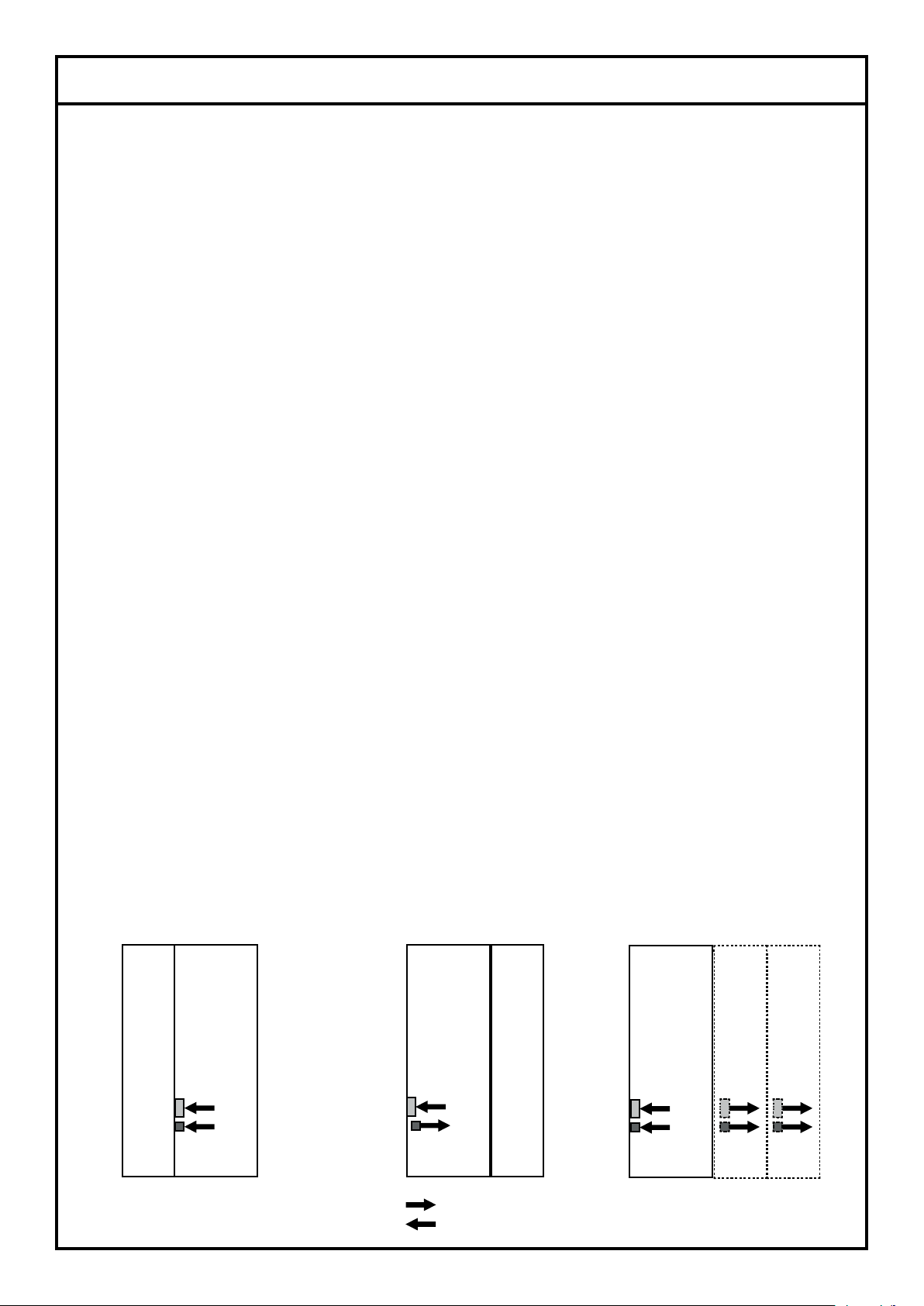
- using the MicLine X input module, AUX 1 is set post fade
while AUX 2 and 3 are set pre fade. None of these can be
switched.
The Master X unit features a switch (positioned on the circuit
board) that deactivates the summing function of its AUX 1
section. If you change this switch from its default setting (AUX
1 on) to AUX 1 off, AUX 1 on the Master X unit will stop
running and the Spring unit (analog spring reverb) will “take
over” the AUX 1 signals from all channels. In this situation,
you can however still pick up the summed AUX 1 signal from
the reverb unit for external use.
The combination of these switches allows you to connect up
to one Spring (post fade) with 5 stage monitors (pre fade),
or up to one Spring with 3 other external effects (post fade)
and two stage monitors (pre fade on AUX 2 and 3).
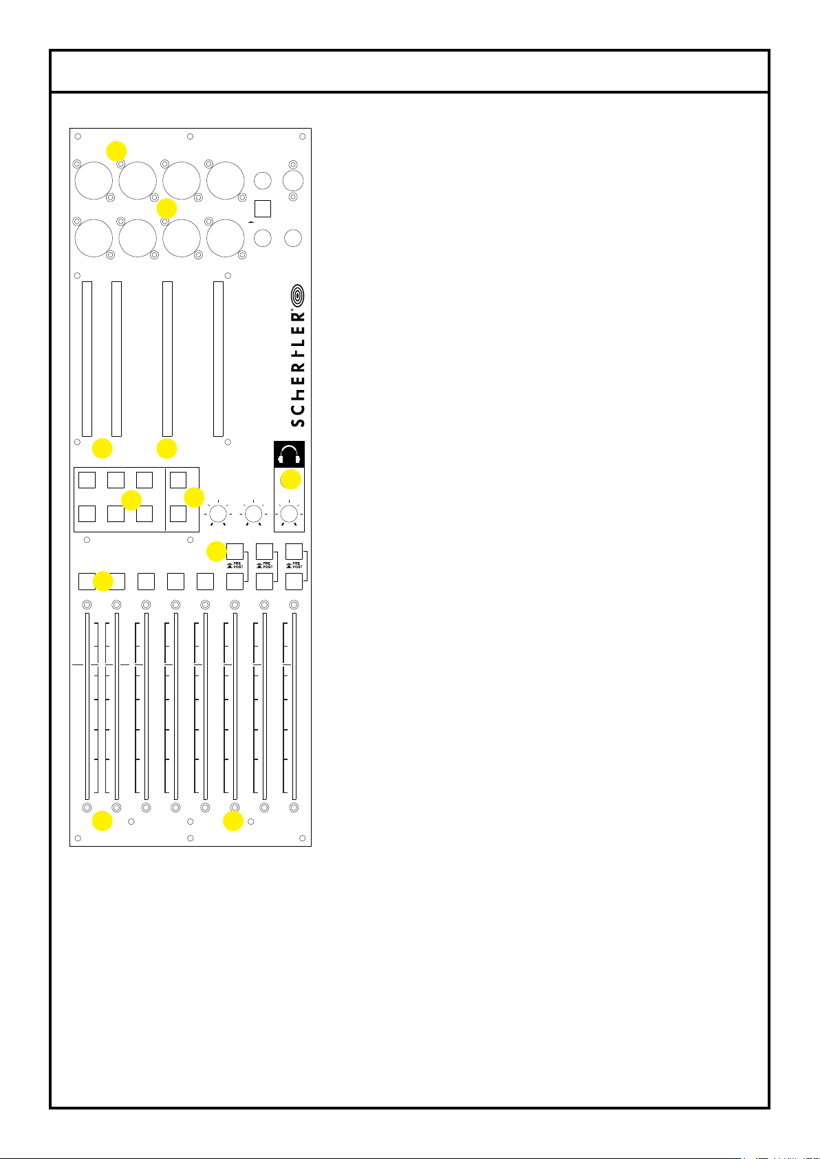
12. PFL VU meter: This shows the sum of the PFL signals
activated on the input modules.
13. PFL Out: ¼-inch balanced jack output connector.
14. Control Room outputs: ¼-inch jack balanced L/R
output connectors.
15. PFL, Control Room and Phones volume: These
rotary controls respectively determine the output volume
from the PFL Out (13), Control Room outputs (14) and
Phones output.
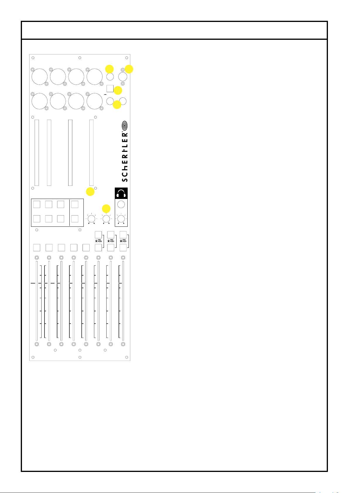
16. DC IN connector: The mixer’s power supply is
connected here. From this 48-volt DC input, all other units
attached to the Master X will also be served via the power
supply. (For more information, please see the Schertler
website (Arthur48/ Accessories).
17. Ground lift button: Sometimes the shielding of the
audio cables can be connected to ground through the
other devices connected to the mixer. However, to avoid
any possible ground loop noises, the GND LIFT button
ART48-MASTER X
disconnects the ground from all audio output ground connector contacts (XLR and jacks). If you have
customized your Master X with transformers on the outputs (see the section on Customization), it is
better to always keep the ground connection lifted, in order to get the most “noiseless” audio signal.
CUSTOMIZATION
Thanks to its innovative ground connection system, Master X’s default conguration has electronically
balanced outputs. However, as an optional extra, it is also possible to customize the output sound by
equipping each of the L/R Master and AUX 1-6 XLR outputs with a Lundahl transformer.
If you have bought your Master X without any transformers, or perhaps with just a few, you can
always send the module back to Schertler and upgrade it with as many transformers as you need.
For example, if you know that some of your stage monitors require the transformers and others
don’t, you may just want to equip selected AUX lines with the transformers, as opposed to all six.
PFL OUT
Left Right
master left
master right
0
+4
+6
-3
-20
-25
-30
-
8
ON - L ON - R
master left
master right
dB
0
+4
+6
-3
-20
-25
-30
8
dB
0
+4
+6
-3
-20
-25
-30
8
dB
0
+4
+6
-3
-20
-25
-30
8
dB
0
+4
+6
-3
-20
-25
-30
8
dB
0
+4
+6
-3
-20
-25
-30
8
dB
0
+4
+6
-3
-20
-25
-30
8
dB
AUX1
AUX2
AUX3
AUX4
AUX5
AUX6
DC IN
LEFT RIGHT AUX 1 AUX 2
AUX 3 AUX 4 AUX 5 AUX 6 CONTROL ROOM
balanced outputs
ON - 1 ON - 2 ON - 3 ON - 4 ON - 5 ON - 6
OUT
VOLUMECONTROL ROOM
VOLUME
PFL
VOLUME
L / R
PFL
AUX 1 AUX 2 AUX 3
AUX 4 AUX 5 AUX 6
to phones andAUX meter
to phones
GND LIFT
AUX 1-6
PFL
+12
+10
+6
+4
0
-3
-6
-10
-16
-20
-24
-28
-32
-36
+12
+10
+6
+4
0
-3
-6
-10
-16
-20
-24
-28
-32
-36
+12
+10
+6
+4
0
-3
-6
-10
-16
-20
-24
-28
-32
-36
dBu dBu dBu
format
48
master x
Arthu r
12.
13.
14.
15.
16.
17.

ART48-MASTER X
COMBINING MASTER MODULES (MASTER X and L/R MASTER)
A standard mixer used for live and recording applications only needs one master L/R for connection
to a PA system, or a recording device etc. There are however numerous situations in which more than
one L/R output is not only useful, but essential.
The Arthur concept, which offers total exibility, enables the combination of a quasi-innite number
of outputs. In a hotel audio installation for example, a microphone and a stereo input might be
sufcient for inputting the sound source, but more outputs would be needed for it to be independently
controllable in different areas such as the bar, restaurant or hotel lobby. Another example could be
a “splitter mixer” for audio demonstration, requiring only one stereo input module (for the audio
source), but numerous master modules for sending the music signal to different loudspeakers for A/B
comparison. Even on a standard mixer, a second master output could be helpful for controlling a
subsidiary part of the PA system, or side lls for example.
The mixer’s structure only allows for one summing amp, which will sum all L and R signals coming from
the BUS. The Master X unit features a white switch - positioned on the circuit board - to deactivate
that summing function. If you are using more than one master module, only one of these should be
left with its default setting (i.e. with summing on); all the other master modules must have both the
blue and white switch depressed.
Note: If you want to position an Arthur SPRING reverb to the right of the Master (forming the nal
unit on the right of the mixer as many users prefer), you must rst deactivate the summing amp on
the Master X. Do this by depressing the blue button on the Master X circuit board.
Spring on the left
side of the Master
Spring on the right
side of the Master
Multiple Masters
setup
SPRING
SPRING
MASTER X
MASTER X
MASTER X
ADDITIONAL
L/R MASTER
ADDITIONAL
L/R MASTER
Released
Depressed

ART48 - MASTER X: SIGNAL FLOW
TECHNICAL INFORMATION

TECHNICAL INFORMATION
L/R and AUX 1 to 6
balanced XLR outputs
Output impedance
Maximum output level
Frequency response (-3 dB)
Distortion (THD+N; @1 kHz)
-30 dBu input level
0 dBu output level
with MICLINE-X module
CTRL room L/R balanced
1/4” jack output
Output impedance
Maximum output level
Maximum Gain
Frequency response (-3 dB)
Distortion (THD+N; @1 kHz)
-30 dBu input level
0 dBu output level
PFL balanced 1/4” jack
output
Output impedance
Maximum output level
Maximum Gain
Frequency response (-3 dB)
Distortion (THD+N; @1 kHz)
-30 dBu input level
0 dBu output level
With transformer
150 ohm
+30 dBu
<10 Hz - 50 kHz
0.075% (Total)
0.08% (2nd harm.)
0.005% (3rd harm.)
0.0008% (4th harm.)
0.001% (5th harm.)
180 ohm
+30 dBu
+10 dB
<10 Hz - 50 kHz
0.05%
180 ohm
+24 dBu
+9 dB
<10 Hz - 50 kHz
0.05%
Without transformer
153 ohm
+30 dBu
<10 Hz - 50 kHz
0.136% (Total)
0.032% (2nd harm.)
0.126% (3rd harm.)
0.003% (4th harm.)
0.019% (5th harm.)

TECHNICAL INFORMATION
Phones ¼” jack output:
Output impedance
Maximum output level
Maximum Gain
Frequency response (-3 dB)
Distortion (THD+N; @1 kHz)
-30 dBu input level
0 dBu output level
Power consumption
Size & weight
Optional Transformers
(Lundahl)
Turns ratio
No load impedance
Frequency response (@10 dBu)
6 ohm
+14.5 dBu
+9 dB
<10 Hz - 55 kHz
0.05%
380 mA (Transformerless)
460 mA (Full transformers)
143x58x475mm
1.65 kg (Transformerless)
2.4 kg (Full Transformers)
1+1 : 1+1
>700 ohm @ 50 Hz, +20 dBU
20 Hz - 80 kHz +/- 0.3 dB

NOTES

APPENDIX
WARRANTY
All Schertler products are covered by a limited two-year factory warranty (from the date of purchase)
in respect of manufacturer defects. Details can be obtained from your local dealer / representative.
Schertler S.A. strongly believes in “common sense”. Therefore, misuse of our products is not covered
under rights obtained through our warranty policy, or through internationally recognised terms and
conditions. For more information on warranty, please visit the Schertler website.
PRODUCT DISPOSAL
This product must not be disposed of in general household waste. It should be taken to a disposal
centre for electrical / electronic waste. Please note any local or national regulations that may be
applicable here.
TRADEMARKS
The SCHERTLER® name and logo are registered trade names / trademarks of SCHERTLER S.A.
Switzerland. All SCHERTLER® products use proprietary technology and are covered by one or
more worldwide patents.
DISCLAIMER
All information and technical specications published here are based on data that was available at
the time of publication. Schertler is, however, constantly aiming to improve its range of products and
therefore reserves the right to amend product specications and information without notice.
Schertler takes no responsibility for any direct or indirect damage (including loss of prot), which
arises as a result of, or in connection with the information in this manual.
COPYRIGHT
This manual is the property of Schertler S.A. and, as such, is subject to Swiss copyright law. No part
of this manual should be reproduced, edited or distributed without prior consent from Schertler.

This manual suits for next models
1
Table of contents