Schiedel ICS User manual

www.schiedel.com/uk
ICS
Installation Instructions
SCHIEDEL INSTALLER
REWARDS
DON'T FORGET TO REGISTER YOUR INSTALLATIONS
AND START EARNING SCHIEDEL INSTALLER REWARDS
See inside for more details
SAP 940002195 - October 2021

2
Contents
Approvals
ICS is CE Certified to EN1856-1 TÜV 0036 CPR 9195 001 with designations:
ICS is CE Certified to EN1856-2 TÜV 0036 CPR 9195 041 with designations
High Temperature
Applications EN1856-1
Low Temperature
Applications EN1856-1
Connecting Flue Pipe
EN1856-2
T450 N1 W V2 L50050 G60
T450 N1 D V3 L50050 G60
60mm distance
to combustibles in
a combustible shaft *
T450 N1 W V2 L50050 G50
T450 N1 D V3 L50050 G50
50mm distance
to combustibles in
a non combustible shaft
or in free air *
T200 P1 W V2 L50050 O00
Zero distance
to combustibles *
T450 NI D V2 L50050 G100M
• Manufactured under a Quality Management Scheme approved to BS EN ISO 9001
• 4 Hour Fire Rating to BS476 Part 20
• Certified for corrosion resistance on gas, oil and solid fuel by Gastec, MPA and TÜV
• HETAS listed for use on solid fuel applications.
* For full information please see p.8 - Distance to Combustibles Section
Approvals..................................................................................................................................................................2
Design Guide..........................................................................................................................................................3
Prior to Installation .............................................................................................................................................4
Connecting Flue Pipe ...................................................................................................................................5-6
BS EN 15287-1...................................................................................................................................................7-8
System Chimney............................................................................................................................................ 9-11
Installation Instructions............................................................................................................................12-17
Double Wall Adjustable Starter Section .....................................................................................18-19
Offset Dimensions....................................................................................................................................20-21
Firestop Components.............................................................................................................................22-23
Support Components.............................................................................................................................24-27
Typical Installations....................................................................................................................................28-31
Protect Box ...........................................................................................................................................................32
Support Components.............................................................................................................................33-35
System Design .............................................................................................................................................36-38
Typical External Installations...................................................................................................................... 39
Load Bearing Data............................................................................................................................................40
Component Weights......................................................................................................................................40
After Installation.................................................................................................................................................41
Notice Plate...........................................................................................................................................................41
Product Guarantee...........................................................................................................................................42
Schiedel Installer Rewards............................................................................................................................42
Useful Guides.......................................................................................................................................................43

3
Design Guide
MANDATORY REQUIREMENTS
Connection to an appliance which is not connected to the fuel supply, should be carried out
by a competent person. We recommend the use of HETAS approved installers for solid fuel
applications. If installation is carried out by a non HETAS registered installer, the installation must
be certified by a local Building Control inspector. Connection to an appliance that is connected
to the fuel supply must be carried out by a Gas Safe (Gas) or OFTEC (Oil) registered installer.
The design guide must be read in conjunction with the detailed component installation
instructions. For full design and installation details the key referral documents are:
• BS EN 1856-1: Chimneys - System Chimney Products
• BS EN 1856-2: Connecting Flue Pipes
• BS EN 1859: Metal Chimneys - Testing Methods
• BS EN 1443: Chimneys - General Requirements
• BS EN 15287-1: Chimneys. Design, installation and commissioning of chimneys. Chimneys for
non-room sealed heating appliances.
• BS 5440-1: Fluing and ventilation for gas appliances of rated input not exceeding 70kW net
(1st, 2nd and 3rd family gases).
Specification for installation of gas appliances to chimneys and for maintenance of chimneys.
• Approved Document J: - Combustion appliances and fuel storage systems (England & Wales)
• DFP Technical Booklet L: - Combustion appliances and fuel storage systems (NI)
• Technical Handbook (Domestic & Non Domestic), Section 3 - Environment (Scotland)
• Appliance Installation Instructions and related standards. Other standards covering specific
applications will also be relevant and must be adhered to.
Planning permission may be required, and reference should be made to the local Building
Control Department.
Ensure all chimney components are available and check them to ensure there has been no
damage. Do not use damaged components. Build the chimney up through the previous designed
route which should be as straight as possible.

4
Prior to Installation
VENTILATION
It is very important that sufficient air for combustion and ventilation is provided to the
room containing the appliance, to enable correct and efficient working of the appliance and
chimney system. Reference should be made to the appliance manufacturer’s instructions and
recommendations are also given in the Building Regulations Document J, CIBSE guidance notes
and BS 5440.
CARBON MONOXIDE ALARMS
The carbon monoxide alarms should comply with BS EN 50291
Where a new or replacement fixed solid fuel appliance is installed in a dwelling, a carbon
monoxide alarm must be provided in the room where the appliance is located.
Please follow manufacturer’s instructions with regards to siting and fixing or alternatively :-
a) On the ceiling at least 300mm from any wall or if it is located on a wall, as high up as possible
(above any doors and windows), but not within 150mm of the ceiling and
b) between 1m and 3m horizontally from the appliance.
N.B Provision of a carbon monoxide alarm should not be regarded as a substitute for correct
installation and regular servicing.
PAINTING
If painting of any external sections is required, it is important to de-grease, dry and prime the
exterior surface prior to the application of appropriate heat resistant paint. Schiedel Chimney
Systems can provide to special order, chimney sections and accessories painted to an extensive
range of British Standard RAL colours – details on application.
Please note that conditions in coastal areas means that corrosion is more likely to occur. Please
contact us for advice on any such installation.
HANDLING
It is advised that suitable PPE should be used when handling the products.
DELIVERY TO SITE AND STORAGE
Components should be carefully transported and off loaded. They should be inspected to
ensure they have not been damaged, and should be stored off the ground and under cover so
that they are protected from accidental damage and the adverse effects of weather.

5
Connecting Flue Pipe
APPLIANCE/CHIMNEY CONNECTION
Connection to the appliance can be made using Prima Smooth, Prima Plus or alternative
approved single wall connecting flue pipes, or ICS.
This must be done by using the appropriate appliance connector. When a single wall connecting
flue pipe is used to connect an appliance to the chimney, the lower end of the chimney section
must extend a minimum of 425mm below the ceiling. When connecting the appliance to the
flue pipe all joints between the flue pipes/appliance outlet must be securely caulked and sealed
with non asbestos rope (or suitable alternative) and fire cement on solid fuel appliances and
using the appropriate lip seal gasket in the case of condensing appliances.
Any flue pipe connection to the chimney MUST be made in the same room as the appliance.
CONNECTION TO DRAUGHT DIVERTER
Where the appliance features a draught diverter the connection should rise vertically from it
for at least 600mm before any change of direction (unless otherwise specified by the appliance
manufacturer). This is in accordance with the recommendations contained in BS 5440 Part 1
section 4.1.5.
CONNECTING FLUE PIPE DIAMETER
The chimney size should be as recommended by the appliance manufacturer. Where there
is a requirement for a flue diameter smaller than the appliance spigot, then the operational
requirements of the appliance and the configuration of the flue must satisfy the flue sizing
requirements of EN13384-1 for single appliances, and EN13384-2 for multi appliances.
DISTANCE TO COMBUSTIBLES
In accordance with building regulations, it is essential that the correct distance to combustible
material is maintained on connecting flue pipes. On solid fuel applications, where there is a risk
of soot fire, on unmeasured (NM) designated single wall product, this distance is 3 x ØInt of
the pipe, e.g. for Ø130mm the distance is 390mm and for Ø150mm the distance is 450mm to
combustibles on both painted and non painted variants. On measured (M) single wall or double
wall products this distance will be as declared by the chimney manufacturer. On ICS25, when
used as a connecting flue pipe, this distance has been measured and is set at 100mm.

6
CONNECTING FLUE PIPE ROUTE
Single wall connecting flue pipes should only be used to connect appliances to a Chimney. They
should not pass through any roof space, partition, internal wall or floor, except to pass directly
into a chimney through a wall of the chimney.
Connecting flue pipes should be located as to avoid igniting combustible material.
On solid fuel appliances the maximum length of a connecting flue pipe is 2m. This distance is
reduced to 1.5m if any of the acceptable alternative methods of connection are adopted as per
BS EN15287-1. (See p.5-6 for full details.)
On appliances with a top outlet, it is recommended that a vertical run of at least 600mm should
be allowed immediately above the appliance prior to any change of direction.
On appliances with a rear outlet, it is recommended that there is maximum of 150mm in the
horizontal run however under certain conditions, as described in alternative methods in BS EN
15287-1, this may be increased to 450mm. (See p.5-6 for full details.)
Within a system (Chimney + Connecting Flue Pipe) there should be no more than 4 changes of
direction of maximum 45˚. 90˚ Factory made bends or tees within the system may be treated
as being equal to two 45˚ bends (as per Document J of the Building Regulations issued October
2010).
INSPECTION
On solid fuel applications to conform to Building Regulations, provisions should be made to
enable a chimney to be inspected and cleaned.
An inspection pipe, inspection elbow or a 90° or 135° Tee with tee cap can form a suitable
inspection point (unless cleaning/inspection can be done through the appliance). To aid cleaning,
sufficient distance should be left between changes of direction to permit the safe passage of
cleaning brushes within the system. This is particularly important on solid fuel applications. It is
recommended that chimneys serving solid fuel appliances be swept as frequently as necessary,
but at least twice a year.
Connecting Flue Pipe

7
BS EN 15287-1
Acceptable alternative Methods of connection
Where a horizontal connecting flue of more than 150mm is required to connect a solid fuel fired
appliance to a chimney, an installation method as per the examples below may be used provided
the following criteria is met:-
a. The maximum length of horizontal connecting flue pipe does not exceed 450mm;
b. A Defra exempt appliance or an appliance, which is limited to burning authorised smokeless
fuel only, is installed;
c. A calculation according to BS EN13384-1 has indicated safe operation of the proposed
configuration, and the results of the calculation are left with the householder along with the
appliance installation instructions;
d. The appliance manufacturer agrees in writing to the proposed configuration;
e. The chimney manufacturer agrees in writing to the proposed configuration;
f. The total length of single wall connecting flue pipe is not more than 1.5m;
g. The appropriate distances to combustible materials from both the appliance and the
connecting flue pipe are maintained.
Top Outlet Single Wall Connecting Flue Pipe
through Solid Wall into Twin Wall System
Chimney
NB Where the connecting flue pipe from the
appliance passes through any wall other than
the existing chimney wall, the connecting flue
pipe must be a System Chimney of twin wall
insulated design.
Top Outlet Twin Wall Connecting Flue Pipe
through Solid Wall into Twin Wall System
Chimney
For minimum distance for
this configuration check
manufacturers distance
to combustibles
Measured from back
of appliance to outside
surface of chimney
Measured from back
of appliance to liner
of masonry chimney
Twin Wall
Chimney System
300
Wall Support
Tee Cap for
Debris Collection/
Cleaning Access
Wall Sleeve
Trim Collar
Cavity Wall Wall Band
450mm MAX 300
450mm MAX
External Masonry
Chimney System
Inspection/
Cleanout Door
Cavity Wall
Wall Sleeve
Trim Collar
Debris
Collector
Wall Sleeve
Trim Collar
100100
225 square
(9” x 9”)
Flexible Twin Wall
Chimney Liner
Chimney Wall
Support Bracket
Swept Elbow
Sweep access
Tee Piece
Single Wall to
Flex Connector
450mm
MAX
Measured from
back of appliance
to flue liner
Wall Support
Measured from back
of connecting flue
pipe to outside
surface of chimney
Tee Cap for
Debris Collection/
Cleaning Access
Twin Wall
Chimney System
Solid Wall
Inspection Bend
Wall Sleeve
Trim Collar
600 min
225
For minimum distance for
this configuration check
manufacturers distance
to combustibles
No further
bends allowed
on this
configuration
Wall Band
450mm MAX
Measured from back
of connecting flue
pipe to outside
surface of chimney
Tee Cap for
Debris Collection/
Cleaning Access
Twin Wall
Chimney System
Solid Wall
Inspection Bend
Wall Sleeve
Trim Collar
225
Wall Support
Wall Band
450mm MAX
600 min
For minimum distance for
this configuration check
manufacturers distance
to combustibles
No further
bends allowed
on this
configuration
Flexible Twin Wall
Chimney Liner
Inspection/
Cleanout Door
Inspection Bend
Wall Sleeve
Trim Collar
Chimney Wall
Support Bracket
Tee Piece
Tee Cap for
Debris Collection/
Cleaning Access
Single Wall to
Flex Connector
225 square
(9” x 9”)
450mm
MAX
For minimum distance for
this configuration check
manufacturers distance
to combustibles
For minimum distance for
this configuration check
manufacturers distance
to combustibles
For minimum distance for
this configuration check
manufacturers distance
to combustibles
Measured from back
of connecting flue pipe
to flue liner
No further
bends allowed
on this
configuration 600 min
100100

8
Top Outlet Twin Wall Connecting Flue
Pipe into Re-lined Masonry Chimney
Rear Outlet Twin Wall Connecting Flue Pipe
Through Cavity Wall into Twin Wall System
Chimney
Rear Outlet Twin Wall Connecting Flue
Pipe into Re-lined Masonry Chimney
Rear Outlet Twin Wall Connecting Flue Pipe
into External Masonry Chimney through a
Cavity Wall
For minimum distance for
this configuration check
manufacturers distance
to combustibles
Measured from back
of appliance to outside
surface of chimney
Measured from back
of appliance to liner
of masonry chimney
Twin Wall
Chimney System
300
Wall Support
Tee Cap for
Debris Collection/
Cleaning Access
Wall Sleeve
Trim Collar
Cavity Wall Wall Band
450mm MAX 300
450mm MAX
External Masonry
Chimney System
Inspection/
Cleanout Door
Cavity Wall
Wall Sleeve
Trim Collar
Debris
Collector
Wall Sleeve
Trim Collar
100100
225 square
(9” x 9”)
Flexible Twin Wall
Chimney Liner
Chimney Wall
Support Bracket
Swept Elbow
Sweep access
Tee Piece
Single Wall to
Flex Connector
450mm
MAX
Measured from
back of appliance
to flue liner
Wall Support
Measured from back
of connecting flue
pipe to outside
surface of chimney
Tee Cap for
Debris Collection/
Cleaning Access
Twin Wall
Chimney System
Solid Wall
Inspection Bend
Wall Sleeve
Trim Collar
600 min
225
For minimum distance for
this configuration check
manufacturers distance
to combustibles
No further
bends allowed
on this
configuration
Wall Band
450mm MAX
Measured from back
of connecting flue
pipe to outside
surface of chimney
Tee Cap for
Debris Collection/
Cleaning Access
Twin Wall
Chimney System
Solid Wall
Inspection Bend
Wall Sleeve
Trim Collar
225
Wall Support
Wall Band
450mm MAX
600 min
For minimum distance for
this configuration check
manufacturers distance
to combustibles
No further
bends allowed
on this
configuration
Flexible Twin Wall
Chimney Liner
Inspection/
Cleanout Door
Inspection Bend
Wall Sleeve
Trim Collar
Chimney Wall
Support Bracket
Tee Piece
Tee Cap for
Debris Collection/
Cleaning Access
Single Wall to
Flex Connector
225 square
(9” x 9”)
450mm
MAX
For minimum distance for
this configuration check
manufacturers distance
to combustibles
For minimum distance for
this configuration check
manufacturers distance
to combustibles
For minimum distance for
this configuration check
manufacturers distance
to combustibles
Measured from back
of connecting flue pipe
to flue liner
No further
bends allowed
on this
configuration 600 min
100100
For minimum distance for
this configuration check
manufacturers distance
to combustibles
Measured from back
of appliance to outside
surface of chimney
Measured from back
of appliance to liner
of masonry chimney
Twin Wall
Chimney System
300
Wall Support
Tee Cap for
Debris Collection/
Cleaning Access
Wall Sleeve
Trim Collar
Cavity Wall Wall Band
450mm MAX 300
450mm MAX
External Masonry
Chimney System
Inspection/
Cleanout Door
Cavity Wall
Wall Sleeve
Trim Collar
Debris
Collector
Wall Sleeve
Trim Collar
100100
225 square
(9” x 9”)
Flexible Twin Wall
Chimney Liner
Chimney Wall
Support Bracket
Swept Elbow
Sweep access
Tee Piece
Single Wall to
Flex Connector
450mm
MAX
Measured from
back of appliance
to flue liner
Wall Support
Measured from back
of connecting flue
pipe to outside
surface of chimney
Tee Cap for
Debris Collection/
Cleaning Access
Twin Wall
Chimney System
Solid Wall
Inspection Bend
Wall Sleeve
Trim Collar
600 min
225
For minimum distance for
this configuration check
manufacturers distance
to combustibles
No further
bends allowed
on this
configuration
Wall Band
450mm MAX
Measured from back
of connecting flue
pipe to outside
surface of chimney
Tee Cap for
Debris Collection/
Cleaning Access
Twin Wall
Chimney System
Solid Wall
Inspection Bend
Wall Sleeve
Trim Collar
225
Wall Support
Wall Band
450mm MAX
600 min
For minimum distance for
this configuration check
manufacturers distance
to combustibles
No further
bends allowed
on this
configuration
Flexible Twin Wall
Chimney Liner
Inspection/
Cleanout Door
Inspection Bend
Wall Sleeve
Trim Collar
Chimney Wall
Support Bracket
Tee Piece
Tee Cap for
Debris Collection/
Cleaning Access
Single Wall to
Flex Connector
225 square
(9” x 9”)
450mm
MAX
For minimum distance for
this configuration check
manufacturers distance
to combustibles
For minimum distance for
this configuration check
manufacturers distance
to combustibles
For minimum distance for
this configuration check
manufacturers distance
to combustibles
Measured from back
of connecting flue pipe
to flue liner
No further
bends allowed
on this
configuration 600 min
100100
BS EN 15287-1
Acceptable alternative Methods of connection

9
System Chimney
CHIMNEY DIAMETER
The chimney size should be as recommended by the
appliance manufacturer. Where there is a requirement
for a flue diameter smaller than the appliance spigot,
then the operational requirements of the appliance and
the configuration of the flue must satisfy the flue sizing
requirements of EN13384-1 for single appliances, and
EN13384-2 for multi appliances.
CHIMNEY ROUTE
The chimney should remain as straight as possible through its
vertical run to assist flow. Should it be necessary to offset a
chimney run then the following guidelines should be adhered
to:
It is recommended that a vertical run of at least 600mm
should be allowed immediately above the appliance prior to
any change of direction. Within a system, on all fuels, there
should be no more than 4 changes of direction of maximum
45°. Factory made 90° bends or tees within the system may be
treated as being equal to two 45° bends (as per Document J of
the Building Regulations issued October 2010).
CONNECTION TO DRAUGHT DIVERTER
Where the appliance features a draught diverter the
connection should rise vertically from it for at least 600mm
before any change of direction (unless otherwise specified by
the appliance manufacturer). This is in accordance with the
recommendations contained in BS 5440 Part 1 section 6.1.4
DIRECT CONNECTION APPLIANCE TO SYSTEM
CHIMNEY
When connecting from the appliance directly to a system
chimney, the appropriate appliance connector must be used
and the joint between the appliance spigot and the appliance
connector must be securely caulked and sealed with non
asbestos rope (or suitable alternative) and fire cement on solid
fuel appliances.
ICS direct connection
from appliance

10
System Chimney
DISTANCE TO COMBUSTIBLES
In accordance with building regulations, it is essential that the correct distance to combustible
material is maintained. On solid fuel applications, where there is a risk of soot fire, a distance
of 60mm to combustibles must be maintained within a combustible oor and within a
combustible shaft (see Fig.1 below).There is no need to line the area within the floor cavity with
plasterboard; however the ventilated re stop plate and ventilated support plate must be used.
On gas and oil applications, a distance of 50mm to combustibles must be maintained within a
combustible oor and within a combustible shaft. The ventilated re stop plate and ventilated
support plate must be used.
Where the chimney penetrates a non combustible floor and where a non combustible shaft is
used, a distance of 50mm to the shaft is sufficient. In this case, non ventilated re stop plates
and support plates may be used with a ventilated re stop being used where the chimney
penetrates into the roof space.
On bungalow applications where the chimney runs through either a combustible or non-
combustible ceiling, an unventilated bungalow fire stop plate kit can be used. Please note that
an unventilated support plate can not be used above the ceiling in this case. The weight of the
chimney should be supported using the roof support (see p.33). Distance to combustibles must
be respected within the ceiling space (see Fig. 2 below) and mesh frame should be used within
the loft space, which must be ventilated (see Fig. 2 below).
ENCLOSURE/SHAFTS
With the exception of the room containing the appliance, where the chimney passes through
any part of the building, where there is a risk of accidental human contact, i.e a bedroom etc., or
where there is a risk of contact with combustible materials stored in a cupboard or in the roof-
space, the chimney must be enclosed in an appropriate way to meet Building Regulations. This
can be achieved by boxing in the chimney in habitable rooms, or by the use of a protective wire
mesh frame in roof spaces etc. In all cases the minimum distance to any combustible material,
including loft insulation, must be respected according to the table on p.10, and any enclosure
should be ventilated using the appropriate ventilated fire stops (see p.22).
Fig. 1 Fig. 2
Internal House
Combustible Floors
Internal Bungalow (Ventilated Loft Space)
Combustible and Non-Combustible Floors

11
System Chimney
SUPPORT COMPONENTS
The weight of a chimney system is considerable and requires independent support. Minimal
weight should be borne by the appliance. The weight of the chimney can be supported from
floor level by using a base support plate, or floor support; from the wall by using wall support
top plates together with side plates or cantilever brackets; or from first floor level by using a
support plate and clamp fixed to the floor/ceiling joists.
Wall brackets are non load bearing and provide lateral support only. Refer to the load bearing
tables on page 40 for full details of maximum loadings.
Where the flue is freestanding above the roof and its height exceeds 1.5m above the last
support or above the roof, a height of up to 3m can be achieved unsupported using the
extended locking bands at the joint immediately below the last support and on each pipe joint
above the last support.
Alternatively guy wire brackets can be used at the 1.5m level and every 1.5m thereafter in
conjunction with guy wires, or rigid stays (provided by others).
CHIMNEY TERMINATION
For full information regarding to chimney termination, please refer to Annex M of BS EN 15287-
1. As a guide please refer to page 36 of these installation instructions.
TERMINALS
All terminals must be secured with the use of a locking band. On solid fuel appliances, an open
termination is normally recommended. However in certain conditions, rain caps or anti-
downdraught terminals may be used.
Rain caps and anti-downdraught terminals are available in three versions, with anti-bird mesh,
with spark guard, or without mesh. Where a terminal with mesh is used, there is a risk of soot
build up, and therefore regular cleaning is required to avoid blockage, particularly when using oil
or solid fuel.

12
Installation Instructions
JOINTING SYSTEM
All joints in the ICS chimney range, which require a locking band, are made by means of a simple
push fit jointing method. This is achieved by the engineered spigot and socket system having a
pronounced lead-in-edge to ease assembly.
ICS Plus is created by adding a lip seal gasket into the inward bead on the liner of the standard
components, which are suitable for use in condensing applications with a P1 designation. When
installing ICS Plus components, Gaskets should be fitted dry and lubricant applied to the internal
of the female liner socket (see Fig.1 bottom of the page)
ICS
Locking Band
Male Spigot
Stainless Steel
Outer case
Spacer Wire
Female Socket
Insulation
Capillary
Break
Stainless Steel
Inner Liner Lip seal
(TÜV Approved 200Pa)
ICS Plus
STANDARD CHIMNEY SECTIONS (PIPES, TEES AND ELBOWS)
Before assembling chimney sections, slip a locking band over female socket of the chimney
section. Ensure the sections are pushed tightly together, before securing the locking band by use
of the quick release clip. The clip can then be tightened into place by using the tightening bolt.
Note:-joints must NOT occur within floor or ceiling spaces.
All flue gas carrying components must be installed with the direction arrow on the product
label pointing to termination with the external male spigot of the case uppermost.
Fig. 1
Locking Band
Lip Seal
(required for
T200 P1 applications)
Lubricant
(applications
with Lip Seal)

13
Installation Instructions
LOCKING BAND (SUPPLIED WITH EACH COMPONENT WITH A FEMALE SOCKET ON
THE CASE)
A locking band must be fitted to every joint in the system. The band is of stainless steel
construction and is fitted with a quick release clip and a stainless steel tightening bolt.The bolt
can be adjusted to ensure the joint is firmly secured.
STRUCTURAL LOCKING BAND
The structural locking band, which is purchased separately, is used instead of a standard locking
band in a situation where extra structural support is required, for instance where the chimney
height is >1.5m above the last support or above the roof. It is also used to provide extra
support in long horizontal runs. A maximum of 3m unsupported height can be achieved by
fitting the structural locking band on the joint immediately below and on every joint above the
last support. Please see diagram on page 39.
ADAPTORS FROM PRIMA PLUS & PRIMA SMOOTH TO ICS
These components are used to convert from a single wall connecting flue pipe to the ICS
system chimney. The protruding liner should be pushed down inside the female socket of the
connecting flue pipe, with the double wall external case spigot pointing in the direction of the
flue gases.
APPLIANCE CONNECTOR/STARTING CONNECTOR/
STOVE STARTER PIPE
The protruding liner of these components should be pushed
into the appliance spigot with the external male case spigot
pointing upwards.
On solid fuel appliances the appliance connector should be
sealed to the appliance with fire rope and fire cement or high
temperature sealant to provide a gas tight joint. On condensing
appliances the appropriate lip seal should be used.
Appliance Connector
Male Spigot
Protruding Liner

14
Installation Instructions
ADAPTOR TO FLEX/TECNOFLEX PLUS
This component is used to convert from ICS to Flex/TecnoFlex Plus. The Flex/TecnoFlex Plus
is pushed down inside the upstand on the adaptor, secured using self tapping screws and sealed
with fire cement and fire rope to provide a gas tight joint.
ADAPTOR FROM ICS TO PRIMA PLUS
This component is manufactured with an ICS female socket and a Prima Plus female socket, and
is used where there is a requirement to convert from ICS to Prima Plus. The ICS female socket
should be attached to the previous ICS component and the joint secured using the locking band
provided.
INCREASER
This component is used to increase from one diameter to the next diameter (e.g.) 200mm
to 230mm. The component is fitted in the same way as a standard pipe length and should be
secured with the locking band provided.
ANCHOR PLATE
When commencing an installation with a fire chest, hood or similar an anchor plate with plain
end should be used. When extending an existing brick or masonry chimney stack, an anchor
plate must be used which needs to be lined with a TecnoFlex Plus Liner then the anchor plate
with the screw fit connection should be used . The liner of the Anchor Plate should be pushed
into the opening of the fire chest with the plate resting on a bed of fire cement. The plate
should then be fixed onto the concrete slab by masonry screws fitted through the pre-drilled
holes in the plate.
In the case of a chimney extension, the liner of the anchor plate fits down inside the existing
chimney stack. If a TecnoFlex Plus chimney liner is being used then the anchor plate is secured to
the liner by twisting in a clockwise direction. The plate should then be then be bolted to the top
of the existing chimney and sealed using fire cement.

15
Installation Instructions
Anchor Plate
Fig. 1
Lip Seal x 2
( T200 P1
applications only)
Insulation
Joint Band
Adjustable Pipe
Joint
Band
ADJUSTABLE PIPE
The adjustable pipes are delivered as two pre-assembled sections with a joint band and locking
band (see Fig.1). They are used with standard components to achieve an exact length on site
and avoid on-site cutting of components.
1. Calculate the length required. Loosen the joint band and remove the top section of the
adjustable pipe.
2. Remove insulation as required to achieve the correct length.
3. Re-assemble the pipe and cover the joint with the joint band.
4. Fix the adjusted section to standard components using the locking band provided.
Please note that the adjustable pipe is non load bearing.

16
Installation Instructions
INSPECTION LENGTH (DRY SYSTEMS)
The inspection length is a component providing the
facility for flue inspection and cleaning. It is installed as
per a standard pipe section.
INSPECTION LENGTH (CONDENSING SYSTEMS)
The inspection length is a component providing the
facility for flue inspection and cleaning on condensing
or high efficiency appliances with a maximum flue gas
temperature of 250°C, and a positive pressure rating
of up to 200 Pa. It is installed as per a standard pipe
section.
INSPECTION PIPE
The Inspection pipe is a component which provides the
facility to inspect the flue. It is installed as per a standard
pipe section.
MEASURE PIPE
The measure pipe is a component which provides
access to the flue for draught testing or for flue gas
analysis. It is installed as per a standard pipe section.
VERTICAL DRAIN PIPE
This component is used on condensing systems and
provides the facility to collect and drain off condensate
from the chimney. It is installed in the same way as a
standard pipe. It is provided as standard with a 3/4” BSP
fitting.
SW-DW ADJUSTABLE STARTER SECTION
The protruding male spigot of the adaptor slides down
inside the female socket of the Prima Smooth pipe and
the socket of the Prima Smooth pipe slides within the
conical section of the starter adaptor, to a maximum
length of 75mm into the cone with a minimum of 15mm
to ensure a secure connection.
This maximum length of 75mm will leave sufficient
space within the adaptor to allow for thermal expansion
of the single wall pipe and also to allow for the
connecting flue pipe to be removed without cutting, if
the appliance has to be moved for servicing.
Inspection Length
(Dry Systems)
Inspection Length
(Condensing Systems)
Inspection Pipe
100
15 min
SW-DW
Adjustable
Starter
Section
75 max
Prima
Smooth

17
Installation Instructions
ELBOWS AND 90˚ INSPECTION ELBOWS
For offset information on standard elbows, please refer to p.14
Please note that 90° Inspection bends may be incorporated into a connecting flue pipe
arrangement on all fuels, please refer to National Annex of BS EN 15287-1 for specific guidance
re use on solid fuel applications, the diagrams on p.7-8 give guidance.
In cases of top mounted stoves, a minimum vertical height of 600mm from the appliance must
be respected prior to any change of direction in the flue pipe.
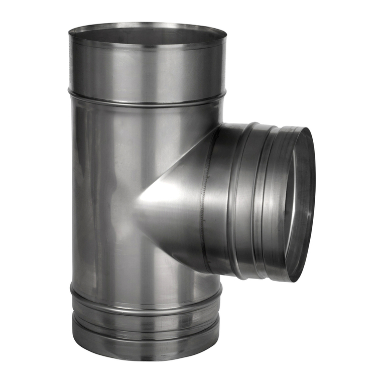
90˚ TEE
This component may be used to connect from a connecting
flue pipe to the vertical system chimney at 90° or the branch
may be used to locate a draft stabiliser. It is installed as per a
standard pipe section.
93˚ TEE
This component must be used in place of a 90° tee to connect
from a connecting flue pipe to the vertical System Chimney
on condensing systems to ensure that condensate can drain
down through the system to a drain point. This component is
installed as per a standard pipe section.
135˚ TEE
This component may be used in combination with a 45° elbow
to connect from a connecting flue pipe to the vertical system
chimney. It is installed as per a standard pipe section and
provides the least resistance to the flow of the flue gases.
Int Ø80 100 130 150 180 200 230 250 300
Ext Ø130 150 180 200 230 250 280 300 350
A145 155 170 180 195 205 220 230 258
B250 270 305 325 355 375 405 425 480
C145 155 170 180 195 205 220 230 258
Int Ø80 100 130 150 180 200 230 250 300
Ext Ø130 150 180 200 230 250 280 300 350
A - 162 178 189 206 216 233 244 264
B - 278 309 329 359 379 405 455 490
C - 166 178 189 206 216 233 257 268
Int Ø80 100 130 150 180 200 230 250 300
Ext Ø130 150 180 200 230 250 280 300 350
A - 262 298 322 358 382 419 443 509
B - 327 375 403 445 474 516 544 622
C - 262 298 322 358 382 419 443 509
90˚ Tee
Ext Ø
B
C
A
Int Ø
93˚ Tee
Ext Ø
B
C
A
Int Ø
135˚ Tee
Ext Ø
B
C
A
Int Ø

18
Double Wall Adjustable Starter Section
Initial installation
Removal of stove for servicing
Remove loose strip of insulation
and keep to one side.
Slide adjustable case up inside the
outer wall of the chimney.
Insulate liner using strip of
insulation with joint to rear. Width
of insulation can be trimmed to
suit.
Insert male spigot of liner into the
appliance spigot.
Remove two loose insulation strips
and keep to one side.
Slide adjustable case down
over the insulation to cover the
appliance spigot.
Finished installation.
Seal using the rope gasket, fire
cement or similar.
Loosen the locking band on the
liner using the quick release clip
(retain the locking band to one
side).
Break the fire cement seal
between the appliance spigot and
chimney liner.
Slide the liner spigot up inside the
chimney until clear of appliance
spigot.
Remove the appliance.
1
1
4
4
2
2
5
5
3
3
6
6

19
Double Wall Adjustable Starter Section
Re-installation of stove after servicing
Position stove spigot immediately
beneath liner spigot of chimney.
Position narrower strip of
insulation around the locking band
with joint
to the rear.
Slide liner spigot down inside the
appliance spigot and seal using the
fire cement, rope gasket or similar.
Slide adjustable cover down 5mm
past insulation. Position final
insulation around spigot with joint
to the rear.
Slide locking band into place
around the joint on the liner. Now
tighten the bolt on the locking
band around the joint of the liner.
Slide adjustable case down
over the insulation to cover the
appliance spigot.
1
4
2
5
3
6

20
Offset Dimensions
(made by assembling 2 bends)
B
B
AA
Int Ø Int Ø Int Ø
B
B
Eff Pipe
Eff Pipe
A
A
Int Ø
Offsets for Double 15˚ Bend
Int Ø 80 100 130 150 180 200 230 250 300
A295 295 295 295 315 315 315 334 334
B39 39 39 39 41 41 41 44 44
Offsets for Double 30˚ Bend
Int Ø 80 100 130 150 180 200 230 250 300
A280 299 327 336 355 373 373 392 411
B75 80 88 90 95 100 100 105 110
Offsets for Double 45˚ Bend
Int Ø 80 100 130 150 180 200 230 250 300
A307 324 341 358 376 393 427 427 461
B127 134 141 148 156 163 177 177 191
Offsets for Double 90˚ Bend
Int Ø 80 100 130 150 180 200 230 250 300
A300 316 348 366 396 420 452 468 518
B300 316 248 366 396 420 452 468 518
B
A
Offsets for 135 Tee˚ & 45˚ Bend
Int Ø 80 100 130 150 180 200 230 250 300
A343 370 437 445 452 496 523 537 592
B305 324 404 406 415 473 475 499 556
This manual suits for next models
2
Table of contents
Other Schiedel Fan manuals
Popular Fan manuals by other brands

Manrose
Manrose LED Series overview

Hunter
Hunter Hunter Ceiling fans Installation and operation manual

Greenheck
Greenheck TAUB-CA Installation, operation and maintenance

Westinghouse
Westinghouse ETL-ES-Comet-WH09 owner's manual

NuTone
NuTone QTNLEDB instructions

Delta Electronics
Delta Electronics KFB1012HHS Dimensions and installation information