7
BS EN 15287-1
Acceptable alternative Methods of connection
Top Outlet Single Wall Connecting Flue Pipe
into Re-lined Masonry Chimney
Rear Outlet Single Wall Connecting Flue
Pipe into Re-lined Masonry Chimney
Top Outlet Single Wall Connecting Flue Pipe
through Solid Wall into Twin Wall System
Chimney
NB Where the connecting flue pipe from the appliance passes
through any wall other than the existing chimney wall, the
connecting flue pipe must be a System Chimney of twin wall
insulated design.
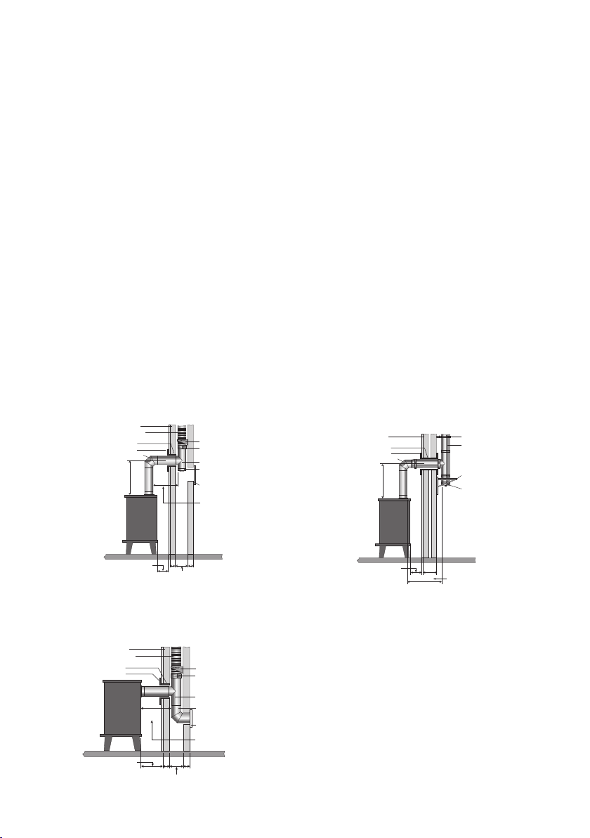
TOP OUTLET SINGLE WALL CONNECTING FLUE PIPE
INTO RE-LINED MASONRY CHIMNEY
No further bends
allowed on this
configeration
Flexible Twin Wall
Chimney Liner
Inspection/
Cleanout Door
Inspection Bend
Wall Sleeve
Trim Collar
Chimney Wall
Tee Piece
Tee Cap for
Debris Collection/Cleaning Access
100 100
225 square
(9” x 9”)
For minimum distance for
this configuration check
manufacturers distance
to combustibles
600 min
Support Bracket
Single Wall to
Flex Connector
450mm
MAX
Measured from back
of connecting flue pipe
to flue liner
TOP OUTLET SINGLE WALL CONNECTING FLUE PIPE
THROUGH SOLID WALL INTO TWIN WALL SYSTEM CHIMNEY
NB Where the connecting flue pipe from the appliance passes
through any wall other than the existing chimney wall, the connecting
flue pipe must be a System Chimney of twin wall insulated design.
Wall Support
Measured from back
of connecting flue pipe
to outside surface
of chimney
Tee Cap for
Debris Collection/Cleaning Access
Twin Wall
Chimney System
Solid Wall
Inspection Bend
Wall Sleeve
Trim Collar
600 min
225
For minimum distance for
this configuration check
manufacturers distance
to combustibles
No further bends
allowed on this
configeration
Wall Band
450mm MAX
REAR OUTLET SINGLE WALL CONNECTING FLUE PIPE
INTO RE-LINED MASONRY CHIMNEY
Wall Sleeve
Trim Collar
100100
225 square
(9” x 9”)
For minimum distance for
this configuration check
manufacturers distance
to combustibles
Flexible Twin Wall
Chimney Liner
Chimney Wall
Support Bracket
Swept Elbow
Sweep access
Tee Piece
Single Wall to
Flex Connector
450mm
MAX
Measured from back
of appliance to flue liner
TOP OUTLET SINGLE WALL CONNECTING FLUE PIPE
INTO RE-LINED MASONRY CHIMNEY
No further bends
allowed on this
configeration
Flexible Twin Wall
Chimney Liner
Inspection/
Cleanout Door
Inspection Bend
Wall Sleeve
Trim Collar
Chimney Wall
Tee Piece
Tee Cap for
Debris Collection/Cleaning Access
100 100
225 square
(9” x 9”)
For minimum distance for
this configuration check
manufacturers distance
to combustibles
600 min
Support Bracket
Single Wall to
Flex Connector
450mm
MAX
Measured from back
of connecting flue pipe
to flue liner
TOP OUTLET SINGLE WALL CONNECTING FLUE PIPE
THROUGH SOLID WALL INTO TWIN WALL SYSTEM CHIMNEY
NB Where the connecting flue pipe from the appliance passes
through any wall other than the existing chimney wall, the connecting
flue pipe must be a System Chimney of twin wall insulated design.
Wall Support
Measured from back
of connecting flue pipe
to outside surface
of chimney
Tee Cap for
Debris Collection/Cleaning Access
Twin Wall
Chimney System
Solid Wall
Inspection Bend
Wall Sleeve
Trim Collar
600 min
225
For minimum distance for
this configuration check
manufacturers distance
to combustibles
No further bends
allowed on this
configeration
Wall Band
450mm MAX
REAR OUTLET SINGLE WALL CONNECTING FLUE PIPE
INTO RE-LINED MASONRY CHIMNEY
Wall Sleeve
Trim Collar
100100
225 square
(9” x 9”)
For minimum distance for
this configuration check
manufacturers distance
to combustibles
Flexible Twin Wall
Chimney Liner
Chimney Wall
Support Bracket
Swept Elbow
Sweep access
Tee Piece
Single Wall to
Flex Connector
450mm
MAX
Measured from back
of appliance to flue liner
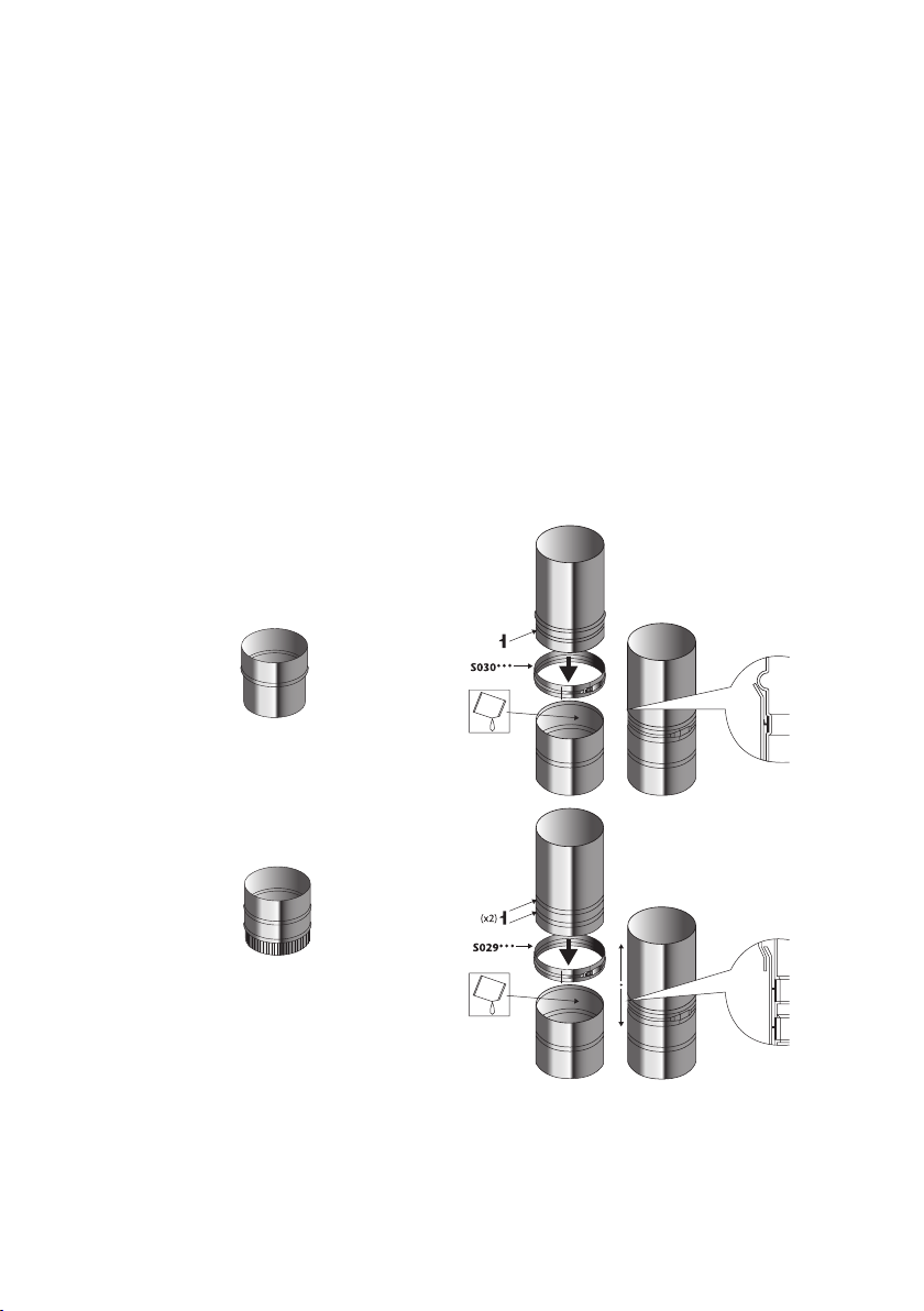
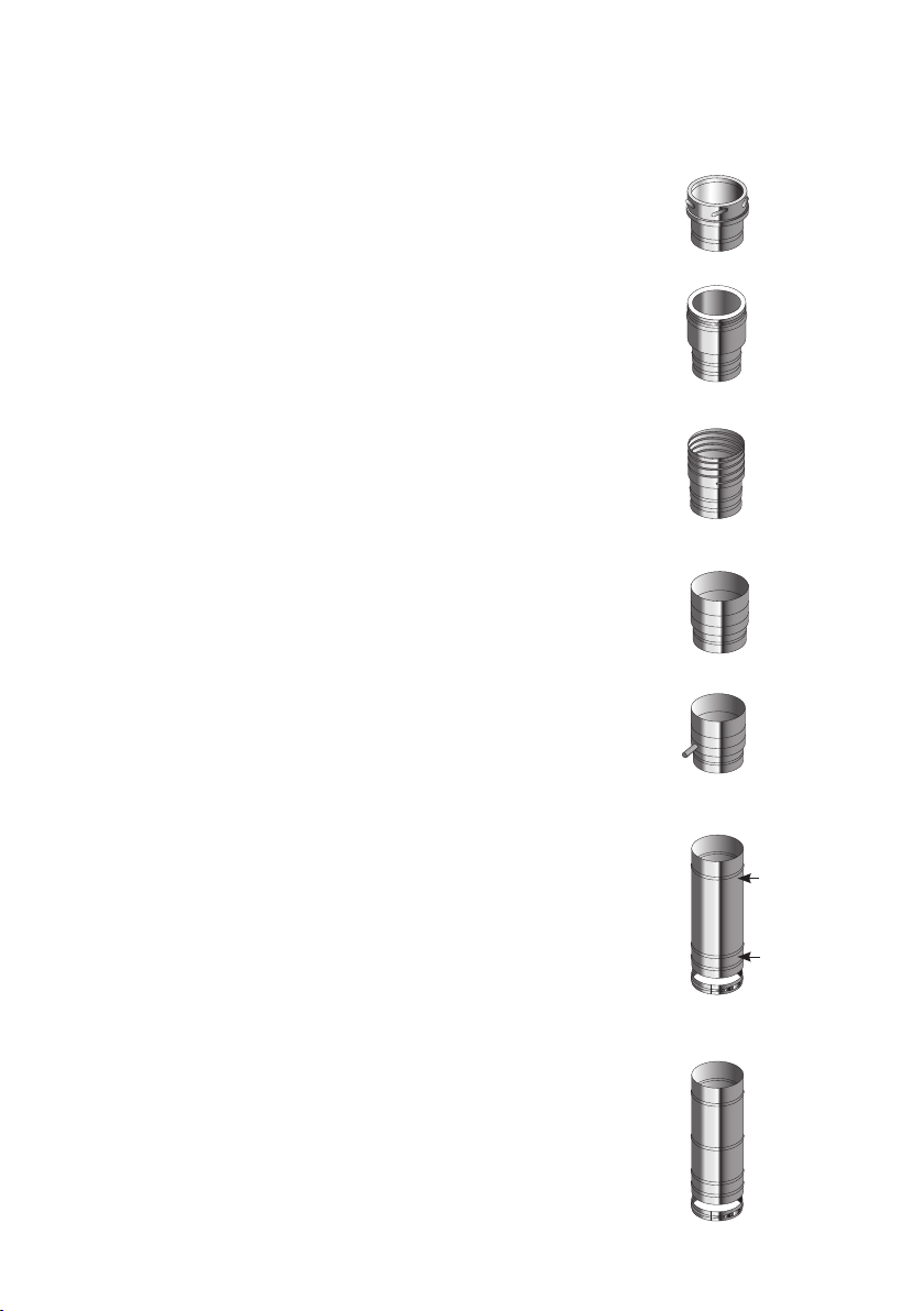
Where a horizontal connecting ue of more than 150mm is required to connect a solid fuel
red appliance to a chimney, an installation method as per the examples below may be used
provided the following criteria is met:-
a. The maximum length of horizontal connecting flue pipe does not exceed 450mm;
b. A Defra exempt appliance or an appliance, which is limited to burning authorised smokeless
fuel only, is installed;
c. A calculation according to BS EN13384-1 has indicated safe operation of the proposed
configuration, and the results of the calculation are left with the householder along with the
appliance installation instructions;
d. The appliance manufacturer agrees in writing to the proposed configuration;
e. The chimney manufacturer agrees in writing to the proposed configuration;
f. The total length of single wall connecting flue pipe is not more than 1.5m;
g. The appropriate distances to combustible materials from both the appliance and the
connecting flue pipe are maintained.