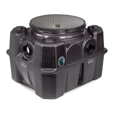
Schier SV10 User manual

Part #: 8065-001-01
Find these instructions online at: schierproducts.com/sv10
Contents
Getting to Know the SV10 . . . . . . . . . . . . . . . . . . . . . . . . . . . . . . . . . . . .2
On the Floor Installation . . . . . . . . . . . . . . . . . . . . . . . . . . . . . . . . . . 3-4
Buried Installation . . . . . . . . . . . . . . . . . . . . . . . . . . . . . . . . . . . . . . . . 5-8
INSTALLATION GUIDE
SV10 Wastewater Sampling Port
© Copyright 2020 Schier, 03/01/2020

GETTING TO KNOW THE SV10
1. Polyethylene Cover with Gasket
2. Quarter-Turn Camlock
Cover Bolts (x2)
3. Safety Star
4. Safety Star Tether
5. 4" Plain End Inlet Connection
6. 6" Plain End Inlet Connection
7. 6" Connection Cut Line (x2)
8. Sampling Port Body
9. Riser Cut Line
10. 6" Plain End Outlet Connection
11. 4" Plain End Outlet Connection
12. 2" x 33" Butyl Mastic Tape Roll (x2)
1
2
3
4
6
7
5
8
9
2
7
10
11
12
page 2 of 8
SV10 Installation Guide

ON THE FLOOR INSTALLATION
page 3 of 8
SV10 Installation Guide
ODOR ALERT!
Do not install air gap on outlet side
of sampling port.
3
Install sampling port as close as
possible to and downstream from
interceptor being served
2
Provide at least 16"
clearance above unit for
routine maintenance.
16" min.
4
1Test sampling port for water tightness
1a For base unit testing, cap
both connection points
with 4" flexible PVC caps.
Remove cover and fill with
water to just above the
highest connection.
Inspect unit and
connections for leaks.
Check water level at
specific time intervals per
local code.
1b
Have a Leak?
Call customer care at 913-951-3300
Hours 8am-5pm CST, M-F
SIDE VIEW
Fill Line
Special Precautions
Do not install this unit in any manner
except as described in these instructions.
Doing so may result in property damage, personal injury or death.
DO NOT AIR TEST UNIT OR RISER SYSTEM!
Read all instructions before installation Install in conformance with all local codes
1

ON THE FLOOR INSTALLATION
2 Connect Piping
2a
4" Plain End
The SV10 sampling port comes from the
factory ready to connect to 4" drain lines.
6" Connections Only
Cut off the 4"
connections at the
premarked cut lines.
Remove any burrs
from the cut.
3 Wet or Air Test Piping Per Local Code
Doing so may result in property damage, personal injury or death.
DO NOT AIR TEST UNIT OR RISER SYSTEM! Leak? Call customer care at
913-951-3300
8a – 5p M – F CST
FLOOR BELOW INSTALLATION DETAIL
Mechanically couple inlet
and outlet drainage lines
to unit.
IMPORTANT! Make sure
the sampling port is
correctly aligned. The SV10
outlet is 2" lower than the
inlet to facilitate sample
retrieval and comply with
local codes. DO NOT
install backwards as
doing so will result in
improper drainage slope.
Do not solvent weld. Vent
per local code.
2b
vent per
local code
DETAIL
Flexible PVC
Coupling
Plain End
Fitting
Drain line
page 4 of 8
SV10 Installation Guide
INLET
OUTLET

BURIED INSTALLATION
page 5 of 8
SV10 Installation Guide
1Test sampling port for water tightness
1a For base unit testing, cap
both connection points
with 4" flexible PVC caps.
Remove cover and fill with
water to just above the
highest connection.
Inspect unit and
connections for leaks.
Check water level at
specific time intervals per
local code.
1b
Have a Leak?
Call customer care at 913-951-3300
Hours 8am-5pm CST, M-F
SIDE VIEW
Fill Line
3 Risers (97") Max
4Max Water Level
Risers are
not designed
to retain water
5
Provide at least 16"
clearance above unit for
routine maintenance.
3
16" min.
2Install sampling port as
close as possible to and
downstream from
interceptor being served
Special Precautions
Do not install this unit in any manner
except as described in these instructions.
Doing so may result in property damage, personal injury or death.
DO NOT AIR TEST UNIT OR RISER SYSTEM!
Read all instructions before installation Install in conformance with all local codes
1

4 Wet or Air Test Piping Per Local Code
Doing so may result in property damage, personal injury or death.
DO NOT AIR TEST UNIT OR RISER SYSTEM! Have a Leak?
Call customer
care at 913-951-3300
Hours 8am-5pm CST, M-F
Excavate hole at least 12" larger than sampling port
on all sides and 6" deeper than port bottom.
Lay a level bed of well-packed, crushed aggregate
(approximately 3/4" size rock or sand, with no fines)
in the base of hole.
2a 2b
6" or more
12" 12"
6"
2 Excavate Burial Pit
BURIED INSTALLATION
4" Plain End
3b
3b1
3 Connect Piping
3a
Lower unit into pit and set level. Mechanically couple inlet
and outlet drainage lines to unit.
IMPORTANT! Make sure the sampling port is correctly
aligned. The SV10 outlet is 2" lower than the inlet to
facilitate sample retrieval and comply with local codes.
DO NOT install backwards as doing so will result in
improper drainage slope.
Do not solvent weld. Vent per local code.
Flexible PVC Couplings
Drainage Lines
The SV10 sampling port comes from the
factory ready to connect to 4" drain lines.
6" Connections Only
Cut off the 4"
connections at the
premarked cut lines.
Remove any burrs
from the cut.
INLET OUTLET
page 6 of 8
SV10 Installation Guide

BURIED INSTALLATION
page 7 of 8
SV10 Installation Guide
5 Bring Cover Flush-to-Grade
The SV10 is ready for burial depth of 14-1/2" from finished grade to bottom of unit (or 10-1/4" to centerline of inlet,
12-1/4" to centerline of outlet). Deeper burials will require adding a risers.
Measure dimension X to determine riser height needed.
5a
Disconnect the SV10 and remove it from
the burial pit. Cut the SV10 at the Riser
Cut Line, freeing the cover adapter from
the sampling port body.
5b
Riser Height Risers
Needed Required
>0" - 31" FCR10
>31" - 64" FCR10 (x2)
>64" - 97" FCR10 (x3)
See instructions included with
FCR10 for installation details.
Install Schier Riser(s) FCR10
5c1
6
OR Install Your Own Riser. The SV10 is designed to accommodate
any non-perforated, 8" nominal diameter drain pipe for riser use.
Sch. 40 PVC or corrugated drain pipe is recommended.
5c2
Return the SV10 to the burial pit
and reconnect the drain lines
45
Place the cover/cover adapter
onto the top of the riser and
check to see if flush with grade.
If too high, remove cover and
trim riser as needed.
2
Insert Riser into
SV10 Body.
1
Cut riser to a length
2" longer than the riser
height needed.
Secure cover/cover adapter using
the other piece of the provided
butyl mastic tape. Make sure joint
is completely sealed and cover is
level and flush-to-grade.
Use 1 piece of the provided
butyl mastic tape to secure
the riser joint. Make sure
joint is completely sealed
and riser is aligned square
to the SV10 Body.
3
x+2"

BURIED INSTALLATION
6 Backfill and Finished Grade
TOP VIEW 18"
min 18"
min
45º
18"
min
18"
min
Concrete Slab
Rebar
Pour concrete slab to finished grade.
6b
Vehicular Traffic Areas:
Minimum 8" thick concrete slab with rebar required. Thickness of
concrete around covers to be determined by specifying engineer. If
traffic loading is required the concrete slab dimensions shown are for
guideline purposes only. Concrete to be 28 day compressive strength
to 4,000 PSI. Use No. 4 rebar (ø 1/2") grade 60 steel per ASTM A615:
connected with tie wire. Rebar to be 2-1/2" from edge of concrete and
spaced in a 12" grid with 4" spacing around access openings.
Pedestrian Traffic or Greenspace Areas:
Minimum 4" thick concrete slab with rebar required.
6b1
Rebar
6a
Backfill evenly around tank using crushed aggregate
(approximately 3/4" size rock or sand with no fines) or
flowable fill. Do not compact backfill around unit.
page 8 of 8
SV10 Installation Guide
Other manuals for SV10
1
Table of contents
Other Schier Water System manuals
Popular Water System manuals by other brands

Everpure
Everpure CV Replacement Cartridge EV9625-01 Specification sheet

Superior Water
Superior Water WATERBOY owner's manual

Dux
Dux Ecosmart 250DPM36 owner's manual

DAB
DAB DIVERTEK Instruction for installation and maintenance

Enapter
Enapter EL4.0 quick start guide

Aqua-Base
Aqua-Base ESW Series owner's manual