SCHMITT SMP Series Installation instructions

Pump series SMP
self-priming magnetically
coupled centrifugal pump
Original operating manual
Version
Print-No. 11335/0320
SCHMITT-Kreiselpumpen GmbH & Co. KG
Einsteinstraße 33
76275 Ettlingen
Germany
Phone: + 49 (0) 7243 / 54 53 - 0
Fax: + 49 (0) 7243 / 54 53 - 22
E-mail: [email protected]
Internet: www.schmitt-pumpen.de
Subject to technical modifications.
Read carefully before use.
Save for future use.

Table of contents
Table of contents
1 About this document ............................... 4
1.1 Target groups ................................. 4
1.2 Other applicable documents ................ 4
1.3 Warnings and symbols ....................... 5
2 General safety instructions ....................... 6
2.1 Intended use .................................. 6
2.2 General safety instructions .................. 6
2.2.1 Product safety ................................ 6
2.2.2 Obligations of the operating company .... . . 6
2.2.3 Obligations of personnel ..................... 7
2.3 Specific hazards .............................. 7
2.3.1 Hazardous pumped liquids .................. 7
2.3.2 Magnetic field ................................. 7
3 Layout and Function ............................... 8
3.1 Marking ....................................... 8
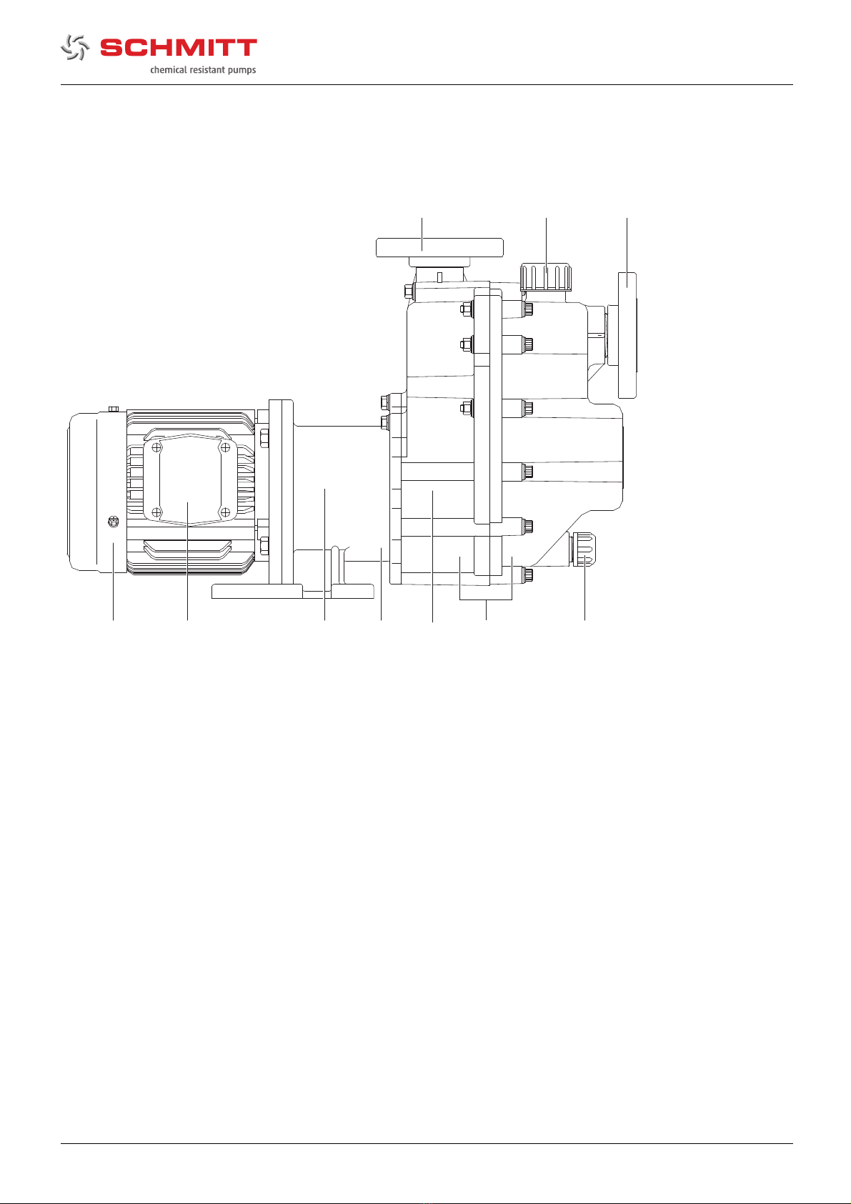
3.2 Description .................................... 8
3.3 Assembly ..................................... 9
3.4 Magnetic coupling ............................ 9
4 Transport, Storage and Disposal ................. 10
4.1 Transport ...................................... 10
4.1.1 Unpacking and inspection on delivery . . . . .. 10
4.1.2 Lifting .......................................... 10
4.2 Storage ....................................... 10
4.3 Disposal ....................................... 10
5 Installation and connection ....................... 11
5.1 Preparing for installation ..................... 11
5.1.1 Check operating conditions ................. 11
5.1.2 Preparing the installation site ............... 11
5.1.3 Prepare foundation and surface ............ 11
5.2 Setting up ..................................... 11
5.3 Planning pipelines ............................ 11
5.3.1 Designing pipelines .......................... 11
5.3.2 Arranging the supports and connec-
tions ........................................... 11
5.3.3 Specifying nominal widths ................... 11
5.3.4 Determine the pipe lengths and installation
parameters ................................... 12
5.3.5 Optimizing changes of cross section and
direction ....................................... 12
5.3.6 Providing safety and control devices
(recommended) .............................. 12
5.4 Connecting the pipes ........................ 12
5.4.1 Keeping the piping clean .................... 12
5.4.2 Installing suction pipe ........................ 12
5.4.3 Installing the pressure pipe .................. 12
5.4.4 Inspection for stress-free pipe
connections ................................... 12
5.5 Electrical connection ......................... 13
5.5.1 Connecting the motor ........................ 13
6Operation ............................................ 14
6.1 Preparing for commissioning ................ 14
6.1.1 Check downtimes ............................ 14
6.1.2 Filling and bleeding .......................... 14
6.1.3 Check direction of rotation ................... 14
6.2 Commissioning ............................... 14
6.2.1 Switching on .................................. 14
6.2.2 Switching off .................................. 15
6.3 Shutting down the pump ..................... 15
6.4 Restoring the pump to service .............. 15
6.5 Operating the stand-by pump ............... 16
7 Maintenance ......................................... 17
7.1 Inspections ................................... 17
7.2 Servicing ...................................... 17
7.2.1 Maintenance in accordance with maintenance
schedule ...................................... 17
7.2.2 Check the plain bearings and replace them
................................................ 18
7.2.3 Cleaning the pump ........................... 19
7.3 Dismounting .................................. 19
7.3.1 Preparations for dismounting ................ 20
7.3.2 Dismount the pump .......................... 20
7.4 Replacement parts and return .............. 20
7.5 Installing ...................................... 21
7.5.1 Preparations for installation ................. 21
7.5.2 Assembly of the pump ....................... 21
7.5.3 Install the pump into the system . . . . . . . . . . . . 22
8 Troubleshooting .................................... 23
9 Appendix ............................................. 26
9.1 Replacement parts ........................... 26
9.1.1 Part numbers and designations ... . . . . . . . . .. 26
9.1.2 Drawings ..................................... 27
9.2 Installation example .......................... 29
9.3 Technical specifications ...................... 30
9.3.1 Ambient conditions ........................... 30
9.3.2 Total pressure ................................ 30
9.3.3 Installation dimensions ...................... 30
9.3.4 Tightening torques of casing screws .... . . . . 30
9.3.5 Pump housing fill volume .................... 30
9.3.6 Suction head after 180 s ..................... 30
9.3.7 Cleaning agents .............................. 30
9.4 Maintenance schedule ....................... 31
9.5 Declaration of conformity .................... 32
2SMP 11335/0320

Table of contents
List of figures
Fig. 1 Name plate (example) ....................... 8
Fig. 2 SMP layout ................................... 9
Fig. 3 Attach the lifting gear to the modular pump
(illustration of general principle) .. . . . . . . . . ... 10
Fig. 4 Pipe lengths and installation
parameters ................................... 12
Fig. 5 Components of the plain bearing ........... 18
Fig. 6 Parts (sectional drawing) .................... 27
Fig. 7 Parts (exploded drawing) .................... 28
Fig. 8 Installation example .......................... 29
Fig. 9 Installation dimension ....................... 30
List of tables
Tab. 1 Other application documents, purpose and
where found .................................. 4
Tab. 2 Warning signs and consequences if
disregarded ................................... 5
Tab. 3 Symbols and their meaning ................. 5
Tab.4 Measurestobetakenifthepumpisshut
down .......................................... 15
Tab. 5 Measures depending on the behavior of the
pumped liquid ................................ 15
Tab. 6 Fault/number assignment ................... 23
Tab. 7 Troubleshooting list .......................... 25
Tab. 8 Designation of components according to part
numbers ...................................... 26
Tab. 9 Ambient conditions ........................... 30
Tab. 10 Tightening torques of casing screws . . . ..... 30
Tab. 11 Pump housing fill volume .................... 30
Tab. 12 Suction head ................................. 30
Tab. 13 Maintenance schedule ....................... 31
11335/0320 SMP 3

About this document
1 About this document
This manual:
• is an integral part of the pump
• applies to all series referred to
• describes safe and proper operation during all operating
phases
1.1 Target groups
Operating company
• Responsibilities:
– Always keep this manual accessible where the device
is used on the system.
– Ensure that employees read and observe this docu-
ment, particularly the safety instructions and warnings,
and the documents which also apply.
– Observe any additional country-specific rules and reg-
ulations that relate to the system.
Qualified personnel, fitter
• Mechanics qualification:
– Qualified employees with additional training for fitting
therespectivepipework
• Electrical qualification:
– Qualified electrician
• Transport qualification:
– Qualified transport specialist
• Responsibility:
– Read, observe and follow this manual and the other
applicable documents, especially all safety instructions
and warnings.
1.2 Other applicable documents
Document/purpose Where found
The following documents are available
online:
• Resistance lists
– Resistance of materials used
to chemicals
• Data sheet
– Technical specifications,
operating conditions,
dimensions
•www.schmitt-pumpen.de/de/
support/downloads.html
Spare parts list
• Ordering spare parts
Sectional drawing
• Sectional drawing, part numbers,
component designations
Documentation for the drive
• Technical documentation for drives
Documentation
included
Declaration of conformity
• Conformity with standards
•(→9.5 Declaration of conformity, Page 32).
Tab. 1 Other application documents, purpose
and where found
4SMP 11335/0320

About this document
1.3 Warnings and symbols
Warning sign Level of risk Consequences if disregarded
DANGER immediate acute risk Death, serious bodily harm
potentially acute risk Death, serious bodily harm
CAUTION potentially hazardous situation Minor injury
NOTE potentially hazardous situation Material damage
Tab. 2 Warning signs and consequences if disregarded
Symbol Meaning
Safety warning sign
Take note of all information highlighted by the safety warning sign
and follow the instructions to avoid injury or death.
Instruction
1., 2., ... Multiple-step instructions
Precondition
→Cross reference
Information, notes
Tab. 3 Symbols and their meaning
11335/0320 SMP 5

General safety instructions
2 General safety instructions
The manufacturer accepts no liability for damages caused
by disregarding any of the documentation.
2.1 Intended use
• Only use the pump with suitable media. Pump parts in con-
tact with media must be resistant to the media. (→Order
specification).
• Adhere to the operating limits and size-dependent mini-
mum flow rates.
• Avoid dry running:
Initial damage, such as destruction of plain bearings, seals
and plastic parts, will occur within a few seconds.
– Make sure the pump is only operated when filled with
the conveyed fluid and never operated when not filled
with the pumped liquid.
– Ensure that there are no excessively high amounts of
gas in the pumping medium.
– Ensure that the pump is operated only within the per-
missible operating range.
– Ensure that the use of shut-off valves or filters does not
cause the pressure on the inlet side of the pump to be
too low.
• Avoid cavitation:
– Fully open the suction-side fitting, if installed.
– Do not open the pressure-side fitting beyond the
agreed operating point.
• Avoid overheating:
– Do not operate the pump while the pressure-side fitting
is closed.
– Note minimum flow (→Data sheet).
• Avoid damage to the motor:
– Do not open the pressure-side fitting beyond the
agreed operating point.
– Note the maximum permissible number of times the
motor can be switched on per hour (→manufacturer's
specifications).
• Consult with the manufacturer regarding any other use of
the device.
Prevention of obvious misuse (examples)
• Observe pump limits of use regarding temperature, pres-
sure, flow and speed (→data sheet).
• The power consumption of the pump increases as the spe-
cific gravity of the pumped fluid increases. Adhere to the
permissible specific gravity in order to eliminate the pos-
sibility that the pump, coupling and motor become over-
loaded (→data sheet).
A lower specific gravity is permissible. Adapt the auxiliary
systems accordingly.
• Do not convey any media containing solids.
• The type of installation should be selected only in accor-
dance with these operating instructions. For example, the
following are not allowed:
– Hanging pumps in the pipe
– Overhead installation
– Installation in the immediate vicinity of extreme heat or
cold sources
– Installation too close to a wall
– Vertical installation
2.2 General safety instructions
Observe the following regulations before carrying out any
work.
2.2.1 Product safety
The pump has been built according to state-of-the-art technol-
ogy and the recognized technical safety regulations. Never-
theless, operation of the pump can still put the life and health
of the user or third parties at risk or damage the pump or other
property.
• Operate the pump only if it is in perfect technical condition
and use it only as intended, staying aware of safety and
risks, and in adherence to the instructions in this manual.
• Keep this manual and all other applicable documents com-
plete, legible and accessible to personnel at all times.
• Refrain from any procedures and actions that would pose
a risk to personnel or third parties.
• In the event of any safety-relevant faults, shut down the
pump immediately and have the fault corrected by appro-
priate personnel.
• In addition to the entire documentation for the product,
comply with statutory or other safety and accident-preven-
tion regulations and the applicable standards and guide-
lines in the country where the pump is operated.
2.2.2 Obligations of the operating company
Safety-conscious working
• Operate the pump only if it is in perfect technical condition
and use it only as intended, staying aware of safety and
risks, and in adherence to the instructions in this manual.
• Ensure that the following safety aspects are observed and
monitored:
– Intended use
– Statutory or other safety and accident-prevention reg-
ulations
– Safety regulations governing the handling of haz-
ardous substances
– Applicable standards and guidelines in the country
where the pump is operated
– Applicable guidelines of the operator
• Make personal protective equipment available.
6SMP 11335/0320

General safety instructions
Qualified personnel
• Make sure all personnel tasked with work on the pump
have read and understood this manual and all other appli-
cable documents, especially the safety, maintenance and
repair information, before they start any work.
• Organize responsibilities, areas of competence and the
supervision of personnel.
• Ensure that all work is carried out by specialist technicians
only:
– Installation, repair and maintenance work
– Transportation
– Work on the electrical system
• Make sure that trainee personnel only work on the pump
under supervision of specialist technicians.
Safety equipment
• Provide the following safety equipment and verify its func-
tionality:
– For hot, cold and moving parts: pump safety guarding
provided by the customer
– For pumps without capability to run dry: Dry run pro-
tection
Warranty
• Obtain the manufacturer's approval prior to carrying out
any modifications, repairs or alterations during the warranty
period.
• Only use genuine parts or parts that have been approved
by the manufacturer.
2.2.3 Obligations of personnel
• All directions given on the pump must be followed (and kept
legible), e.g. the arrow indicating the sense of rotation and
the markings for fluid connections.
• Pump and components:
– Do not step on them or use as a climbing aid
– Do not use them to support boards, ramps or beams
– Do not use them as a fixing point for winches or sup-
ports
– Do not use them for storing paper or similar materials
• Do not remove the safety guarding for hot, cold or moving
parts during operation.
• Use personal protective equipment if necessary.
• Only carry out work on the pump while it is not running.
• Before all installation and maintenance work, disconnect
the motor from the mains and secure it against being
switched back on again.
• Never reach into the suction or pressure-side flange.
• Following all work on the pump, refit safety devices in
accordance with the instructions and bring into service.
• Do not make any modifications to the device.
2.3 Specific hazards
2.3.1 Hazardous pumped liquids
• When handling hazardous fluids, observe the safety regu-
lations for the handling of hazardous substances.
• Use personal protective equipment when carrying out any
work on the pump.
• Collect leaking pumped liquid and residues in a safe man-
ner and damage them in accordance with environmental
regulations.
2.3.2 Magnetic field
Individuals with implanted pacemakers must:
• Be kept away from the pump with magnetic coupling and
parts of the magnetic coupling
• Not be allowed to complete work with, or on, the magnetic
parts
The magnetic field of the magnetic coupling can destroy prod-
ucts that are sensitive to magnets. These include
• Pacemakers
• ID cards with magnetic strips
• Credit cards and check cards
• Electrical, electronic precision devices (e.g. mechanical
and digital clocks, calculators, hard disk drives)
11335/0320 SMP 7

Layout and Function
3 Layout and Function
3.1 Marking
D-76275 Elingen, Germany
www.schmi-pumpen.de Tel.: +49 (0) 7243-5453-0
Typ / Type: SMP 150 PP
SCHMITT - Kreiselpumpen
SNR: 01245678
1
2
45
3
Fig. 1 Name plate (example)
1Type
2 Serial number
3 Pump series
4Size
5 Pump material
3.2 Description
Self-priming and magnetically coupled centrifugal pump in
modular design:
• 2 housing chambers
• Media-lubricated plain bearings
• Direction of conveying
– Flange, suction side, axial (suction pipe vertical)
– Flange, pressure side, vertical
• Conveying from open or closed, but depressurized tanks,
pits or vessels
8SMP 11335/0320

Layout and Function
3.3 Assembly
12
4
3
5678910
Fig. 2 SMP layout
1 Flange, pressure side
2 Filler opening
3 Flange, suction side
4 Exhaust opening
5 Housing (consisting of 2 chambers)
6 Impeller (concealed)
7 Pump support
8 Magnetic coupling (hidden)
9 Terminal box
10 Motor
3.4 Magnetic coupling
Pumps with magnetic couplings are hermetically sealed and
leaktight. Power transmission from the motor is non-contact
through an enclosed and hermetically sealed rear cover on the
impeller.
11335/0320 SMP 9

Transport, Storage and Disposal
4 Transport, Storage and
Disposal
4.1 Transport
The user/owner is responsible for the transport of the
pump.
Weight specification (→Data sheet)
4.1.1 Unpacking and inspection on delivery
1. Unpack the pump/machine drive on delivery, and inspect it
for transport damage.
2. Check completeness and accuracy of delivery.
3. Ensure that the information on the name plate agrees with
the order/design data.
4. Report any transportation damage to the manufacturer
immediately.
5. Dispose of packaging material according to local regula-
tions.
4.1.2 Lifting
DANGER
Death or limbs crushed as a result transported items
falling over!
Use lifting gear appropriate for the total weight to be trans-
ported.
Attach lifting gear in accordance with the following diagram.
Do not stand under suspended loads.
Fig. 3 Attach the lifting gear to the modular pump
(illustration of general principle)
1. Attach lifting gear in accordance with the above diagram.
2. Lift the modular pump appropriately.
4.2 Storage
NOTE
Material damage due to inappropriate storage!
Store the pump properly.
1. Rinse and empty the pump if necessary.
2. Seal all openings with blind plugs or plastic covers.
3. Make sure the storage room meets the following condi-
tions:
–Dry
– Frost-free
– Vibration-free
–UVprotected
4. Rotate the pump shaft once a month.
5. Make sure the shaft and bearing change their rotational
position in the process.
4.3 Disposal
Plastic parts can be contaminated by poisonous or radioac-
tive pumped liquids to such an extent that cleaning will be
insufficient.
WARNING
Risk of poisoning and environmental damage by the
pumped liquid!
Use personal protective equipment when carrying out any
work on the pump.
Prior to the disposal of the pump:
– Collect and damage any escaping pumped liquid in
accordance with local regulations.
– Neutralize residues of pumped liquid in the pump.
Remove plastic parts and damage them in accordance with
local regulations.
Dispose of the pump in accordance with local regulations.
10 SMP 11335/0320

Installation and connection
5 Installation and connection
NOTE
Material damage caused by dirt!
Do not remove the transport seals until immediately before
installing the pump.
Do not remove any covers or transport and sealing covers
until immediately before connecting the pipes to the pump.
5.1 Preparing for installation
5.1.1 Check operating conditions
Ensure the required operating conditions are met:
– Resistance of body and seal material to the medium
(→resistance lists).
– Required ambient conditions
(→9.3.1 Ambient conditions, Page 30).
5.1.2 Preparing the installation site
Ensure the installation site meets the following conditions:
– Pump is freely accessible from all sides
– Sufficient space for the installation/removal of the pipes
and for maintenance and repair work, especially for the
removal and installation of the pump
– Pump not exposed to external vibration (damage to
bearings)
– Pump not exposed to external corrosive influences
– Frost protection
– Distance from the pump to the lowest tank fill level <
max. permissible differential head
5.1.3 Prepare foundation and surface
Aids, tools, materials:
– Spirit level
Ensure the foundation and surface meet the following con-
ditions:
– Level and horizontal
– Clean (no oil, dust or other impurities)
– Capable of bearing the weight of the machine drive and
all operating forces
– Ensures the stability of the machine drive
5.2 Setting up
1. Lift up the machine drive (→4.1 Transport, Page 10).
2. Put down the machine drive at the place of installation.
3. Screw the fastening screws into the flange and tighten
them.
5.3 Planning pipelines
Note the installation example (→9.2 Installation example,
Page 29).
Water hammer may damage the pump or the system. Plan
the pipes and fittings as far as possible to prevent water
hammer occurring.
5.3.1 Designing pipelines
Plan pipes safely:
– No pulling or thrusting forces
– No bending moments
– Adjust for changes in length due to temperature
changes (compensators, expansion shanks)
– Avoid bends close to the pressure-side flange
5.3.2 Arranging the supports and connections
NOTE
Material damage due to excessive forces and torques on
the pump!
Ensure pipe connection without stress.
1. Support pipes in front of the pump.
2. Ensure the pipe supports will always allow expansion and
contraction of the pipes.
5.3.3 Specifying nominal widths
Keep the flow resistance in the pipes as low as possible.
1. Make sure the nominal suction line width is not smaller than
the nominal suction flange width.
2. Make sure the nominal pressure line width is not smaller
than the nominal discharge flange width.
11335/0320 SMP 11

Installation and connection
5.3.4 Determine the pipe lengths and installation
parameters
A
D
Fig. 4 Pipe lengths and installation parameters
A DNs
B≥0.5 m
C≥1.5 x DNs
D DNd
E>5xDNd
Observe recommended minimum values when installing
the pump.
Pressure side: Shorter lengths are possible, but may result
in increased noise development.
5.3.5 Optimizing changes of cross section and
direction
1. Avoid radii of curvature of less than 1.5 times the nominal
pipe diameter.
2. Avoid abrupt changes of cross-section along the piping.
5.3.6 Providing safety and control devices
(recommended)
Avoid contamination
Install a dirt strainer with mesh size <3 mm at the inlet of
the suction pipe.
Avoid reverse running
1. Install a foot valve or check valve between the pressure-
side flange and shut-off valve to ensure that the medium
does not flow back after thepumpisswitchedoff.
2. In order to enable venting, include vent connection
between the pressure-side flange and foot valve or check
valve.
Make provisions for isolating and shutting off the pipes
For maintenance and repair work.
Provide shut-off valves in the suction pipe and pressure
line.
Dry run protection by measuring the operating conditions
Provide monitoring sensors for both pressure and flow rate,
to protect the pump against dry running and
consequential damage.
5.4 Connecting the pipes
NOTE
Material damage due to excessive forces and torques on
the pump!
Ensure pipe connection without stress.
5.4.1 Keeping the piping clean
NOTE
Material damage due to impurities in the pump!
Make sure no impurities can enter the pump.
Clean all piping parts and fittings prior to assembly.
5.4.2 Installing suction pipe
1. Remove the transport and sealing covers from the pump.
2. Fit suction pipe stress-free and sealed.
3. Avoid gas cavities:
– Always lay the suction pipe rising.
– Do not install bends with an angle ≤90°.
– Do not install the suction pipe near whirlpools or supply
lines.
5.4.3 Installing the pressure pipe
1. Remove the transport and sealing covers from the pump.
2. Position the pressure-side flange facing upwards, so as to
allow the pump head to be vented.
3. Fit the pressure line stress-free and sealed.
4. Install the foot valve under the following operating condi-
tions:
– The outlet of the suction pipe is at least 10 m above the
tank fill level height
– Differential head > 15 m
5.4.4 Inspection for stress-free pipe connections
Piping installed and cooled down
1. Disconnect the pipe connections from the pump.
2. Check whether the pipes can be moved freely in all direc-
tions within the expected range of expansion.
3. Make sure that the connections are parallel.
4. Reconnect the pipe connections to the pump.
12 SMP 11335/0320

Installation and connection
5.5 Electrical connection
DANGER
Risk of electrocution!
All electrical work must be carried out only by qualified elec-
tricians.
Before all work on the electrical system, disconnect the
motor from the mains and secure against being switched
back on again.
5.5.1 Connecting the motor
Follow the instructions of the motor manufacturer.
1. Connect the motor according to the connection diagram.
2. Make sure no danger arises due to electric power.
3. Install an EMERGENCY STOP switch.
11335/0320 SMP 13

Operation
6Operation
6.1 Preparing for commissioning
6.1.1 Check downtimes
Before starting up the pump, check the downtime and per-
form the following actions:
– Check the fill level.
– If the hydraulic parts are dirty, clean them.
– Check that the impeller runs freely.
– If the pump is shut down for over 1 year, replace elas-
tomer seals (O-rings, shaft sealing rings).
6.1.2 Filling and bleeding
The pump housing is filled with conveyed fluid. During
commissioning, the suction line is filled fully by the pump
and vented. Additional measures for venting are not
required.
WARNING
Risk of injury and poisoning due to hazardous pumped
liquids!
Use protective equipment for any work on the pump.
Safely collect the fluid and dispose of it in accordance with
environmental regulations.
1. Unscrew the filler cap.
2. Pour in the conveyed fluid. Note the fill volumes
(→9.3.5 Pump housing fill volume, Page 30).
3. Screw the filler cap back on.
6.1.3 Check direction of rotation
DANGER
Danger to life from rotating parts!
Use personal protective equipment when carrying out any
work on the pump.
Maintain an adequate distance from rotating parts.
NOTE
Material damage as a result of dry running!
Make sure the pump is filled properly.
1. Switch on motor for max. 2 seconds and switch it off again
immediately.
2. Visually check the direction of rotation of the motor fan
impeller and make sure that the direction of rotation of the
motor matches the direction arrow on the pump casing.
3. If the sense of rotation is different: Change over the two
phases (→5.5 Electrical connection, Page 13).
6.2 Commissioning
6.2.1 Switching on
Pump set up and connected properly
Motor set up and connected properly
All connections stress-free and sealed
All safety equipment installed and tested for functionality
Pump prepared, filled and vented correctly
Tank fill sufficient
DANGER
Risk of injury and poisoning due to pumped liquid spray-
ing out!
Use personal protective equipment when carrying out any
work on the pump.
NOTE
Risk of cavitation if suction flow is restricted!
Open the suction-side fitting and do not use it to regulate
the flow, if installed.
Do not open the pressure-side fitting beyond the operating
point.
NOTE
Material damage due to overheating!
Do not operate the pump for long periods with the pressure-
side fitting closed.
Observe the minimum flow rate (→9.3.6 Suction head
after 180 s, Page 30).
NOTE
Material damage as a result of dry running!
Make sure the pump is filled properly.
1. Open the suction-side fitting, if installed.
2. Close the pressure-side fitting.
3. Open the exhaust line fitting.
4. Switch on the motor and check it for smooth running.
5. Make sure that the suction pipe and pump are vented fully.
Check the vacuum gauge.
Gas escapes through the exhaust line.
6. Once the motor has reached its nominal speed, open
the pressure-side fitting slowly until the operating point is
reached.
7. Close the exhaust line fitting.
8. Make sure temperature change is smaller than 5 K/min for
pumps with hot fluids.
9. After the initial stress due to the pressure and operating
temperature, check that the pump is not leaking.
14 SMP 11335/0320

Operation
10. If leaks are present at the housing seals or flanges, proceed
as follows:
– Switch off motor.
– Close the control valves.
– Remedy the leaks.
6.2.2 Switching off
Pressure-side fitting closed (recommended)
WARNING
Risk of injury due to hot pump parts!
Use personal protective equipment when carrying out any
work on the pump.
1. Switch off motor.
2. Check all connecting bolts and tighten them if necessary
(only after initial commissioning).
6.3 Shutting down the pump
DANGER
Risk of injury due to running pump!
Do not touch the pump when it is running.
Do not carry out any work on the pump when it is running.
Before all installation and maintenance work, disconnect
the motor from the mains and secure it against being
switched back on again.
DANGER
Risk of electrocution!
All electrical work must be carried out only by qualified elec-
tricians.
Before all work on the electrical system, disconnect the
motor from the mains and secure against being switched
back on again.
WARNING
Risk of injury and poisoning due to hazardous pumped
liquids!
Use protective equipment for any work on the pump.
Collect leaking liquid safely and damage fitting in accor-
dance with local regulations.
Take the following measures whenever the pump is shut
down:
Pump is Action
shut down Take measures appropriate for
the fluid (→Ta b . 5 M e a s u r e s
depending on the behavior of
the pumped liquid, Page 15).
…emptied Close suction and pressure-side
fitting.
…dismounted Isolate the motor from its power
supply and secure it against
unauthorized switch-on.
…put into
storage
Note measures for storage
(→4.2 Storage, Page 10).
Tab. 4 Measures to be taken if the pump is shut down
Duration of shutdown (depending
on process)
Behavior of the
pumped liquid
Short Long
Crystallized or
polymerized,
solids
sedimenting
Flush the
pump.
Flush the
pump.
Solidifying/
freezing,
non-corrosive
Heat up or
empty the
pump and
containers.
Empty the
pump and
containers.
Solidifying/
freezing,
corrosive
Heat up or
empty the
pump and
containers.
Empty the
pump and
containers.
Remains liquid,
non-corrosive
––
Remains liquid,
corrosive
–Empty the
pump and
containers.
Tab. 5 Measures depending on the behavior
of the pumped liquid
6.4 Restoring the pump to service
1. If the pump is shut down for over 1 year, replace elastomer
seals.
2. Complete all steps as for commissioning
(→6.2 Commissioning, Page 14).
11335/0320 SMP 15

Operation
6.5 Operating the stand-by pump
Stand-by pump filled and bled
Suction pipe not vented
Operate the stand-by pump at least once a week.
1. Fully open the suction-side fitting, if installed.
2. Open pressure-side fitting far enough so that the stand-by
pump operating temperature is achieved and heating is
even (→6.2.1 Switching on, Page 14).
16 SMP 11335/0320

Maintenance
7 Maintenance
Opening the pump casing invalidates the warranty.
When used for the intended purpose the bearings and seals are
virtually free of wear and will not require replacement during the
warranty period.
Maintenance and repair work should be undertaken in con-
sultation with Schmitt Kreiselpumpen. The chapter describes
maintenance not within the warranty period.
Maintenance during the warranty period will be performed
by Schmitt Kreiselpumpen. Submit evidence of conveyed
medium on request (DIN safety data sheet or confirmation
of decontamination).
7.1 Inspections
The inspection intervals depend on the operational strain
on the pump.
DANGER
Risk of injury due to running pump!
Do not touch the pump when it is running.
Do not carry out any work on the pump when it is running.
WARNING
Risk of injury and poisoning due to hazardous pumped
liquids!
Use personal protective equipment when carrying out any
work on the pump.
1. Check at appropriate intervals:
– Adherence to the minimum flow rate
– Normal operating conditions unchanged
– Tank fill level
2. For trouble-free operation, always ensure the following:
– No dry running
–Noleaks
– No cavitation
– Shut-off valve open on the suction side, if installed
– Free and clean filters
– Sufficient pump inlet pressure
– No unusual running noises or vibrations
– No parting of magnetic coupling
7.2 Servicing
Plain bearings are subject to natural wear and tear which
is heavily dependent on the respective operating condi-
tions. It is therefore not possible to make general state-
ments about the operating life.
DANGER
Danger to life and material damage due to magnetic field!
Make sure that personnel with pacemakers do not com-
plete work on the pump.
Secure the work place and if necessary cordon off:
– Make sure that personnel with pacemakers keep a safe
distance of > 1 m.
– Make sure that no magnetizable metal parts can be
attracted by the pump's magnetic coupling.
– Make sure that parts of the magnetic coupling cannot
be attracted by the magnetizable metal parts.
Maintainasafedistanceofatleast150mmfromthemag-
netic coupling for magnetically sensitive objects.
DANGER
Risk of injury due to running pump!
Do not touch the pump when it is running.
Do not carry out any work on the pump when it is running.
Before all installation and maintenance work, disconnect
the motor from the mains and secure it against being
switched back on again.
DANGER
Risk of electrocution!
All electrical work must be carried out only by qualified elec-
tricians.
Before all work on the electrical system, disconnect the
motor from the mains and secure against being switched
back on again.
WARNING
Risk of injury and poisoning due to hazardous or hot fluid!
Use personal protective equipment when carrying out any
work on the pump.
Allow the pump to cool completely before commencing any
work.
Make sure the pump is depressurized.
Empty the pump, safely collect the pumped liquid and dam-
age it in accordance with environmental rules and require-
ments.
7.2.1 Maintenance in accordance with main-
tenance schedule
Perform maintenance work in accordance with the mainte-
nance schedule (→9.4 Maintenance schedule, Page 31).
11335/0320 SMP 17

Maintenance
7.2.2 Check the plain bearings and replace them
When changing the plain bearings, refer to the drawings
(→9.1.2 Drawings , Page 27).
Request spare parts from the manufacturer
(→7.4 Replacement parts and return, Page 20).
When checking the plain bearings, inspect the following parts
for damage and exchange them as needed:
•Impeller
• Housing
• Seals and O-rings
Dismount the pump
To allow the plain bearings to be checked and replaced, disas-
semble the pump.
Prepared for disassembly (→7.3.1 Preparations for dis-
mounting, Page 20).
1. Remove the hexagon nuts and washers (12) from the
hexagon socket screws (2).
2. Remove the hexagon socket screws (2).
3. Remove the front pump housing from the rear pump hous-
ing (10).
4. Remove the housing seal (6) and check it for damage. If
necessary dispose of the housing seal and fit a new part.
5. Remove the partition (7).
6. Remove the filter (9), check it for dirt and clean it if neces-
sary.
7. Remove the O-ring (8) and check it for damage. If neces-
sary dispose of the O-ring and fit a new part.
8. Remove the hexagon screws (18).
9. Remove the rear pump housing (10).
10. Remove the O-ring (15) and check it for damage. If neces-
sary dispose of the O-ring and fit a new part.
11. Pull the rear cover (16) with impeller (13) off the external
magnet (19).
12. Remove the seal from the pump support (17) and check it
for damage. If necessary dispose of the seal and fit a new
part.
Check the plain bearings and replace them
16-1 16-2 13-1 10-1
14
Fig. 5 Components of the plain bearing
10-1 Bearing ring, rear housing
13-1 Bearing ring, impeller
14 Bearing bush
16-1 Bearing ring, rear cover
16-2 Fixed axle in the rear cover
NOTE
Material damage due to incorrect use!
Inspect the ceramic parts of the plain bearings carefully; do
not strike them or knock them.
13. Check the bearing ring (10-1) on the rear pump housing
(10) for damage. In case of damage, dispose of the entire
rear housing and fit a new part.
14. Remove the impeller (13) from the rear cover (16).
15. Check the bearing ring (13-1) on the impeller (13) for dam-
age. In case of damage, dispose of the entire impeller and
fit a new part.
16. Check the impeller (13) for dirt and damage. If necessary
clean the impeller or dispose of it,andfitanewpart.
17. Pull the bearing bush (14) off the fixed axle in the rear cover
(16-2) and check it for damage. In case of damage, dis-
pose of the bearing bush and fit a new part.
18. Check the bearing ring (16-1) and the fixed axle (16-2) on
the rear cover (16) for damage. In case of damage, dispose
of the entire rear cover and fit a new part.
19. If necessary, clear the through holes and relief holes.
18 SMP 11335/0320

Maintenance
Installing the pump
20. Slide the impeller (13) onto the bearing bush (14).
21. Slide the bearing bush (14) with impeller (13) onto the fixed
axle in the rear cover (16).
22. Install the O-ring (15) in the rear cover (16).
23. Install the seal in the pump support (17).
24. Insert the rear cover (16) together with the impeller (13) into
the external magnets (19).
25. Install the rear housing (10) on the pump support (17) and
tighten the hexagon screws (18) hand-tight.
26. Install the filter (9).
27. Install the O-ring (8).
28. Install the partition (7).
29. Install the housing seal (6).
30. Install the front pump housing on the rear pump hous-
ing (10).
31. Install the hexagon socket screws (2).
32. Tighten the hexagon nuts with washers (12) and hexagon
screws (18) crosswise (→9.3.4 Tightening torques of cas-
ing screws, Page 30).
33. Spin the motor fan impeller and make sure that the
impeller (13) runs freely in the plain bearings.
7.2.3 Cleaning the pump
NOTE
High water pressure or spray water can cause material
damage!
Do not direct water jets or steam jets into the opening of
the pump support.
Regularly clean the pump to remove heavy dirt.
7.3 Dismounting
DANGER
Danger to life and material damage due to magnetic field!
Make sure that personnel with pacemakers do not com-
plete work on the pump.
Secure the work place and if necessary cordon off:
– Make sure that personnel with pacemakers keep a safe
distance of > 1 m.
– Make sure that no magnetizable metal parts can be
attracted by the pump's magnetic coupling.
– Make sure that parts of the magnetic coupling cannot
be attracted by the magnetizable metal parts.
Maintainasafedistanceofatleast150mmfromthemag-
netic coupling for magnetically sensitive objects.
DANGER
Risk of injury due to running pump!
Do not touch the pump when it is running.
Do not carry out any work on the pump when it is running.
Before all installation and maintenance work, disconnect
the motor from the mains and secure it against being
switched back on again.
DANGER
Risk of electrocution!
All electrical work must be carried out only by qualified elec-
tricians.
Before all work on the electrical system, disconnect the
motor from the mains and secure against being switched
back on again.
WARNING
Risk of injury and poisoning due to hazardous or hot fluid!
Use personal protective equipment when carrying out any
work on the pump.
Allow the pump to cool completely before commencing any
work.
Make sure the pump is depressurized.
Empty the pump, safely collect the pumped liquid and dam-
age it in accordance with environmental rules and require-
ments.
WARNING
Risk of injury due to heavy components!
Pay attention to the component weight. Lift and transport
heavy components using suitable lifting gear.
Set down components safely and secure them against
overturning or rolling away.
11335/0320 SMP 19

Maintenance
WARNING
Risk of injury during disassembly!
Secure the pressure-side shut-off valve against accidental
opening.
Wear protective gloves, components can become very
sharp-edged due to wear or damage.
Observe the manufacturer's specifications (e.g. for the
motor).
NOTE
Material damage due to incorrect dismounting/installation
of the pump!
Only specialist mechanics should complete dismounting/
installation work.
7.3.1 Preparations for dismounting
Pump is depressurized
Pump completely empty, flushed and decontaminated
Electrical connections disconnected and motor secured
against switch-on
Pump cooled down
Pressure gauge lines, pressure gauge and fixtures dis-
mounted
1. Dismantle the pipes on the suction and pressure side.
2. Remove pump from the system.
3. When dismounting, observe the following:
– Mark the precise orientation and position of all compo-
nents before dismounting them.
– Dismount components concentrically without canting.
7.3.2 Dismount the pump
Following the drawings for disassembly (→9.1.2 Drawings
, Page 27).
NOTE
Material damage, fragile components!
Perform disassembly carefully, and do not strike or knock
the fragile ceramic parts of the plain bearing.
1. Remove the hexagon nuts and washers (12) from the
hexagon socket screws (2).
2. Remove the hexagon socket screws (2).
3. Remove the front pump housing from the rear pump hous-
ing (10).
4. Unscrew the flange (3).
5. Remove the O-ring (4).
6. Unscrew the filler cap with O-ring (5).
7. Unscrew the exhaust cap (1).
8. Remove the housing seal (6).
9. Remove the partition (7).
10. Remove the filter (9).
11. Remove the O-ring (8).
12. Remove the hexagon screws (18).
13. Remove the rear pump housing (10).
14. Unscrew the flange (11).
15. Remove the O-ring (12).
16. Remove the O-ring (15).
17. Pull the rear cover (16) with impeller (13) off the external
magnet (19).
18. Remove the impeller (13) from the rear cover (16).
19. Pull the bearing bush (14) off the fixed axle in the rear
cover (16).
20. Remove the seal from the pump support (17).
21. Remove the hexagon screws on the motor flange.
22. Remove the pump support (17).
23. Remove the fastening screw from the external magnet (19).
24. Pull the external magnet (19) off the motor shaft.
7.4 Replacement parts and return
1. Have the following information as shown on the name plate
ready to hand when ordering spare parts (→3.1 Marking,
Page 8 ).
– Serial number
–Type
2. Please complete and enclose the confirmation of decon-
tamination for returns
(→www.schmitt-pumpen.de/de/support/downloads.html).
3. Use only spare parts from SCHMITT.
20 SMP 11335/0320
This manual suits for next models
1
Table of contents
Other SCHMITT Water Pump manuals
Popular Water Pump manuals by other brands

Wilo
Wilo SiFire Easy Installation and operating instructions

Intex
Intex Krystal Clear 604 owner's manual

Wilo
Wilo Helix2.0-VE Installation and operating instructions

AMICOCIRC
AMICOCIRC AMICO 20-4-130 Handbook

Liberty Pumps
Liberty Pumps Builder S30 Series installation manual

Parkside
Parkside PKZ 180 C5 Original instructions

AMT
AMT 3160-99 Specifications information and repair parts manual

Grundfos
Grundfos SE1 50 Installation and operating instructions

Wilo
Wilo Rexa UNI Installation and operating instructions

Crane
Crane BARNES RIVAL RV101A installation manual

SPX
SPX Power Team PE55-E110 Series operating instructions

Roughneck
Roughneck 24925 owner's manual