8
GB
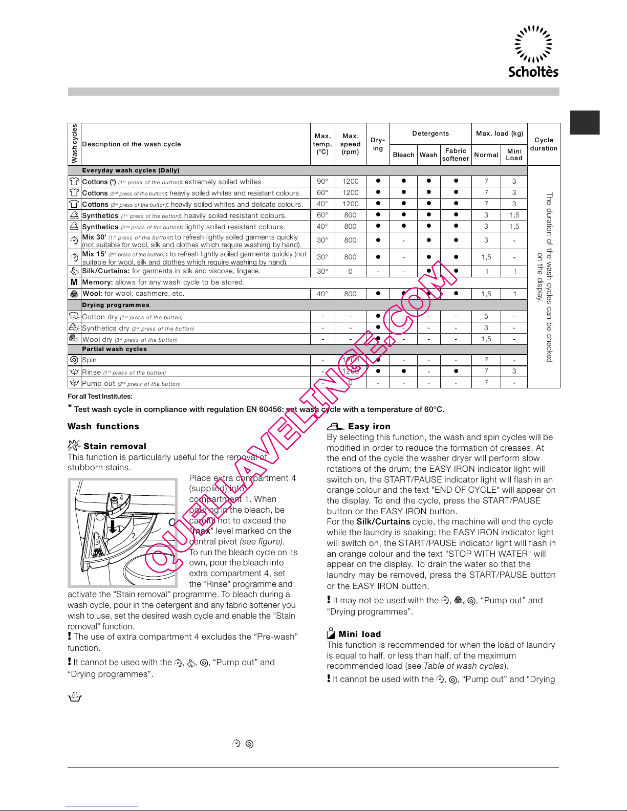
How to run a wash cycle or a
drying cycle
1. SWITCH THE MACHINE ON.Press the button; the
text WELCOME will appear on the display and the START/
PAUSE indicator light will flash slowly in a green colour.
2. LOAD THE LAUNDRY. Open the porthole door. Load
the laundry, aking sure you do not exceed the
axi u load value indicated in the table of
progra es on the following page.
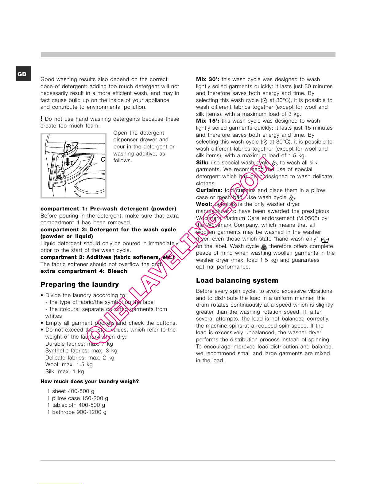
3. MEASURE OUT THE DETERGENT. Pull out the
detergent dispenser drawer and pour the detergent into
the relevant co part ents as described in "Detergents
and laundry".
4. CLOSE THE DOOR.
5. SELECT THE WASH CYCLE. Press one of the WASH
CYCLE SELECTOR buttons to select the required wash
cycle; the na e of the wash cycle will appear on the
display. A te perature and spin speed is set for each
wash cycle; these ay be adjusted. The duration of the
cycle will appear on the display.
6. CUSTOMISE THE WASH CYCLE. Use the relevant
buttons:
Modifying the temperature and/or spin
speed.The achine auto atically selects the axi u
te perature and spin speed set for the selected wash
cycle; these values cannot therefore be increased. The
te perature can be decreased by pressing the
button, until the cold wash "OFF" setting is reached. The
spin speed ay be progressively reduced by pressing
the button, until it is co pletely excluded (the "OFF"
setting). If these buttons are pressed again, the
axi u values are restored.
Setting a delayed start.
To set a delayed start for the selected progra e,
press the corresponding button repeatedly until the
required delay period has been reached. When this
option is enabled, the sy bol lights up on the
display. To re ove the delayed start function press the
button until the text "OFF" appears on the display.
Setting the drying cycle.
The desired drying cycle type ay be set by pressing
the DRYING button once or several ti es. Two options
are available:
A - Based on the how da p the clothes are once they
have been dried:
Iron dry: slightly da p clothes, easy to iron.
Hanger dry: dry clothes to put away.
Cupboard dry: very dry clothes, reco ended for
towelling and bathrobes.
B - Based on ti e: fro 40 inutes to 180.
To exclude the drying phase press the relevant button
until the text OFF appears on the display.
If your laundry load to be washed and dried is uch
greater than the axi u stated load (see adja ent
table), perfor the wash cycle, and when the cycle is
co plete, divide the gar ents into groups and put so e
of the back in the dru . At this point, follow the
instructions provided for a "Drying only" cycle. Repeat
this procedure for the re ainder of the load.
N.B: a cooling-down period is always added to the end
of each drying cycle.
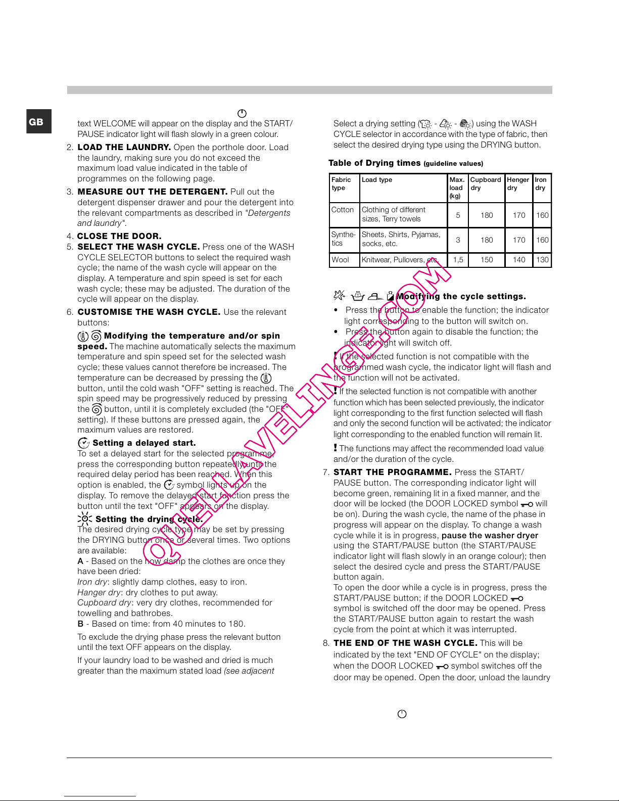
Drying only
Select a drying setting ( - - ) using the WASH
CYCLE selector in accordance with the type of fabric, then
select the desired drying type using the DRYING button.
Modifying the cycle settings.
Press the button to enable the function; the indicator
light corresponding to the button will switch on.
Press the button again to disable the function; the
indicator light will switch off.
If the selected function is not co patible with the
progra ed wash cycle, the indicator light will flash and
the function will not be activated.
If the selected function is not co patible with another
function which has been selected previously, the indicator
light corresponding to the first function selected will flash
and only the second function will be activated; the indicator
light corresponding to the enabled function will re ain lit.
The functions ay affect the reco ended load value
and/or the duration of the cycle.
7. START THE PROGRAMME. Press the START/
PAUSE button. The corresponding indicator light will
beco e green, re aining lit in a fixed anner, and the
door will be locked (the DOOR LOCKED sy bol will
be on). During the wash cycle, the na e of the phase in
progress will appear on the display. To change a wash
cycle while it is in progress, pause the washer ryer
using the START/PAUSE button (the START/PAUSE
indicator light will flash slowly in an orange colour); then
select the desired cycle and press the START/PAUSE
button again.
To open the door while a cycle is in progress, press the
START/PAUSE button; if the DOOR LOCKED
sy bol is switched off the door ay be opened. Press
the START/PAUSE button again to restart the wash
cycle fro the point at which it was interrupted.
8. THE END OF THE WASH CYCLE.This will be
indicated by the text "END OF CYCLE" on the display;
when the DOOR LOCKED sy bol switches off the
door ay be opened. Open the door, unload the laundry
and switch off the achine.
If you wish to cancel a cycle which has already begun,
press and hold the button. The cycle will be stopped
and the achine will switch off.
Fabric
type
Loa type Max.
loa
(kg)
Cupboar
ry
Henger
ry
Iron
ry
Cotton Clothing of different
sizes, Terry towels 5 180 170 160
Synthe-
tics Sheets, Shirts, Pyja as,
socks, etc. 3 180 170 160
Wool Knitwear, Pullovers, etc. 1,5 150 140 130
Table of Drying times (guideline values)