10
GB
How to run a wash cycle or a
drying cycle
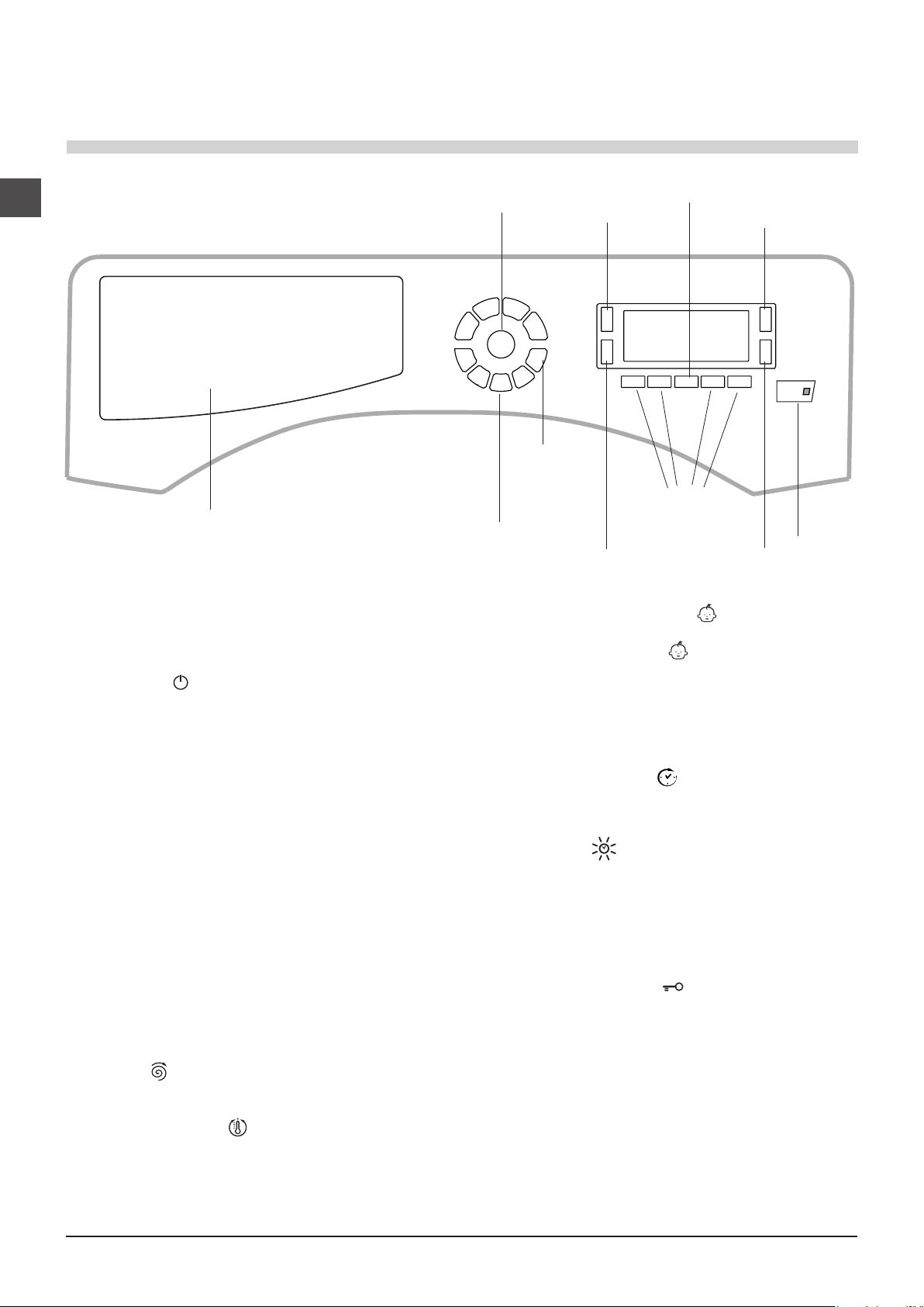
1. SWITCH THE MACHINE ON. Press the button; the
text WELCOME will appear on the display and the START/
PAUSE indicator light will flash slowly in a green colour.
2. LOAD THE LAUNDRY. Open the porthole door. Load the
laundry, making sure you do not exceed the maximum load
value indicated in the table of programmes on the following
page.
3. MEASURE OUT THE DETERGENT. Pull out the
detergent dispenser drawer and pour the detergent into
the relevant compartments as described in “Detergents
and laundry”.
4. CLOSE THE DOOR.
5. SELECT THE WASH CYCLE. Press one of the WASH
CYCLE SELECTOR buttons to select the required wash
cycle; the name of the wash cycle will appear on the
display. A temperature and spin speed is set for each wash
cycle; these may be adjusted. The duration of the cycle will
appear on the display.
6. CUSTOMISE THE WASH CYCLE. Use the relevant
buttons:
Modifying the temperature and/or spin
speed. The machine automatically selects the maximum
temperature and spin speed set for the selected wash
cycle; these values cannot therefore be increased. The
temperature can be decreased by pressing the button,
until the cold wash “OFF” setting is reached. The spin
speed may be progressively reduced by pressing the
button, until it is completely excluded (the “OFF” setting). If
these buttons are pressed again, the maximum values are
restored.
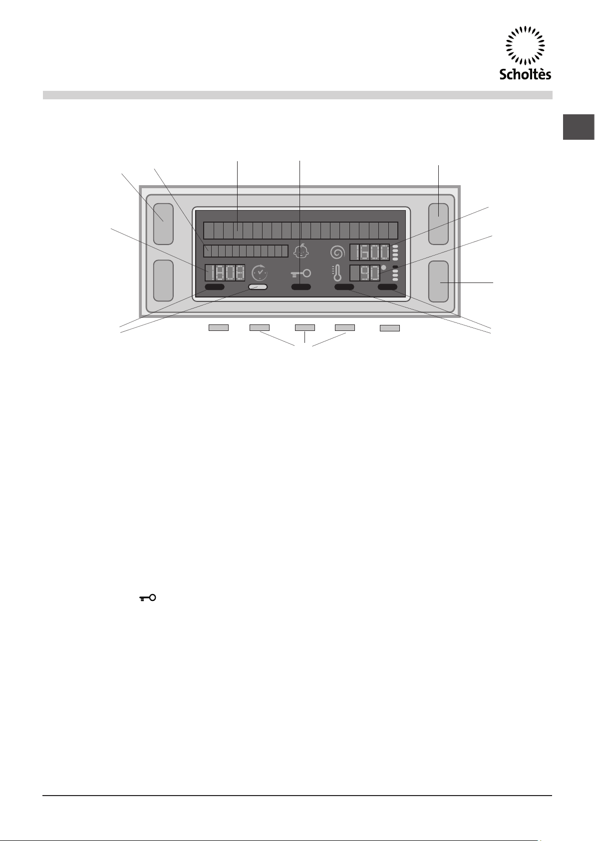
Setting a delayed start.
To set a delayed start for the selected programme, press
the corresponding button repeatedly until the required
delay period has been reached. When this option is
enabled, the symbol lights up on the display. To remove
the delayed start function press the button until the text
“OFF” appears on the display.
Setting the drying cycle.
The desired drying cycle type may be set by pressing the
DRYING button once or several times. Two options are
available:
A- Based on the how damp the clothes are once they
have been dried:
Iron dry: slightly damp clothes, easy to iron.
Hanger dry: dry clothes to put away.
Cupboard dry: very dry clothes, recommended for
towelling and bathrobes.
B- Based on time: from 40 minutes to 180.
To exclude the drying phase press the relevant button until
the text OFF appears on the display.
If your laundry load to be washed and dried is much greater
than the maximum stated load (see adjacent table), perform
the wash cycle, and when the cycle is complete, divide
the garments into groups and put some of them back in
the drum. At this point, follow the instructions provided
for a “Drying only” cycle. Repeat this procedure for the
remainder of the load.
N.B: a cooling-down period is always added to the end of
each drying cycle.
Drying only
Select a drying setting ( - - ) using the WASH
CYCLE selector in accordance with the type of fabric, then
select the desired drying type using the DRYING button.
Modifying the cycle settings.
• Press the button to enable the function; the indicator
light corresponding to the button will switch on.
• Press the button again to disable the function; the
indicator light will switch off.
!If the selected function is not compatible with the
programmed wash cycle, the indicator light will flash and
the function will not be activated.
!If the selected function is not compatible with another
function which has been selected previously, the indicator
light corresponding to the first function selected will flash
and only the second function will be activated; the indicator
light corresponding to the enabled function will remain lit.
!The functions may affect the recommended load value
and/or the duration of the cycle.
7. START THE PROGRAMME. Press the START/PAUSE
button. The corresponding indicator light will become
green, remaining lit in a fixed manner, and the door will be
locked (the DOOR LOCKED symbol will be on). During
the wash cycle, the name of the phase in progress will
appear on the display. To change a wash cycle while it is
in progress, pause the washer dryer using the START/
PAUSE button (the START/PAUSE indicator light will flash
slowly in an orange colour); then select the desired cycle
and press the START/PAUSE button again.
To open the door while a cycle is in progress, press the
START/PAUSE button; if the DOOR LOCKED symbol
is switched off the door may be opened. Press the START/
PAUSE button again to restart the wash cycle from the
point at which it was interrupted.
8. THE END OF THE WASH CYCLE. This will be indicated
by the text “END OF CYCLE” on the display; when the
DOOR LOCKED symbol switches off the door may be
opened. Open the door, unload the laundry and switch off
the machine.
!If you wish to cancel a cycle which has already begun, press
and hold the button. The cycle will be stopped and the
machine will switch off.