schroff VARISTAR LHX 3 User manual

Varistar LHX 3 60130-626 Revision 001
1
OPERATING MANUAL
VARISTAR LHX 3
Air/Water Heat Exchanger
V A R I S T A R
Schroff GmbH
Climate Control
Langenalber Strasse 96 - 100, D-75334 Straubenhardt
Telephone + 49 (0) 70 82 794-0

Varistar LHX 3 60130-626 Revision 001
2
Schroff GmbH reserves all rights to this documentation, in particular the right to reproduce,
distribute and translate this document. This also applies in cases of patent and trademark rights.
No part of this documentation may be reproduced, processed, copied or distributed by either
conventional or electronic means without the prior written consent of Schroff GmbH.
We reserve the right to make technical alterations. While this document has been prepared with
great care, we cannot guarantee that it is free of errors.
Schroff assumes no liability for any errors in this documentation. To the maximum extent
permissible by law, Schroff shall not accept liability for any damages arising, directly or
indirectly, from the supply or use of this documentation.
Signs and Symbols
Throughout this operating manual, the notices below are identified by the following symbols
(pictographs):
Danger!
Warning of imminent danger. Failure to observe this warning may result in serious bodily injury
and even death.
Caution!
Warning of a potentially hazardous situation. Failure to observe this warning may result in minor
bodily injury or damage to the equipment.
Information
Identifies important information or user tips.
To be completed by the user :
Inventory number: _____________________
Installation site: _____________________
Schroff serial number: _____________________
Contact Address:
Schroff GmbH
Langenalber Straße 96-100
D-75334 Straubenhardt,
Germany
Tel.: (+49) (0) 7082 794-130
Fax: (+49) (0) 7082 794-200
E-mail: [email protected]
www.schroff.de

Varistar LHX 3 60130-626 Revision 001
3
Contents
Page
1. Description of the Air/Water Heat Exchanger (LHX 3) 4
1.1 Principle of Operation 4
1.2 Controls 4
1.3 Benefits
2. Regulations / Safety Notices 5
3. LHX 3 Technical Data 6
3.1 Performance Curves 7
4. WaterQuality 8
5. Transport and Storage 8
6. Assembly 9
6.1 Removing the LHX 3 from the wooden pallet 9
6.2 Removing and rotating the LHX 3 heat exchanger cassette 10
6.3 Fitting the fan unit 11
6.4 Water supply 12
6.4.1 Water supply from rear 12
6.4.2 Water supply from front 12
6.5 Drainage of condensate 13
7. Decommissioning 14
8. Environmental Requirements 14
9. Malfunctions and Troubleshooting 15
10. Maintenance and Servicing 16
11. Conditions of Warranty 17
11.1 Warranty term 17
11.2 Scope of fault correction under warranty 17
11.3 Exclusions from warranty 17
11.4 Making a claim under the warranty 17
12. EC Declaration of Conformity as defined in EC Guidelines 18

Varistar LHX 3 60130-626 Revision 001
4
1. Description of the Air/Water Heat Exchanger (LHX 3)
This unit is designed to remove the high levels of dissipated heat generated by electronic racks
and components used in electronics and industry from the electronics or server cabinets in
which they are installed. The LHX 3 is based on the VARISTAR series and contains a space-
independent cooling system.
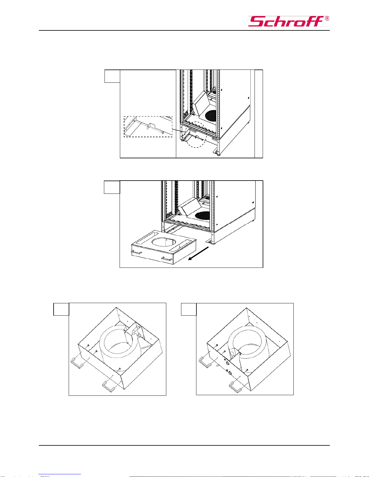
The system comprises a top fan, air channels in both side panels and a removable air/water
heat exchanger in the base of the cabinet.
The LHX 3 is designed for maintenance-free operation.
1.1 Principle of Operation
Warm air in the cabinet is sucked upward by a top fan into air channels which are integrated
into side panels.
Cooling water enters the heat exchanger, is warmed by extracting heat from the air, and flows
back to the cooling-water circuit. Meanwhile the air, now cooled, is reintroduced into the cabinet
from below.
General Remarks for Effective Cooling
An effective usable cooling capacity of the LHX 3 is achieved by:
- optimal positioning of the electronic components housed in the cabinet
- suitable guiding of the airflow
- air baffles fitted to increase functional effectiveness
1.2 Controls
The LHX 3 is not adjustable.
1.3 Benefits
The LHX 3 is based on a space-independent thermal concept and does not affect its
surroundings.
At full load the LHX 3 generates a noise level of no more than 45.2dB (A) and can thus be used
in an office environment.
Since the air/water heat exchanger is situated in the base, the LHX 3 does not pose a danger to
the installed systems from water leakage. Nor is there any danger of air short-circuits since the
fan (in the top panel) is spatially separated from the heat exchanger (in the base).

Varistar LHX 3 60130-626 Revision 001
5
2. Regulations / Safety Notices
The design and construction of the LHX 3 are in compliance with all applicable EC guidelines.
(See section 12, EC Declaration of Conformity)
In the installation and operation of the LHX 3 the following regulations and safety notices must
be observed:
ANY WORK ON THE LHX 3 MAY ONLY BE CARRIED OUT BY QUALIFIED PERSONNEL
ACCIDENT PREVENTION REGULATIONS MUST BE OBSERVED
DO NOT STAND UNDER THE LOAD DURING RAISING AND LOWERING OF THE LHX 3.
KEEP OUT OF THE DANGER AREA.
THE LHX 3 MUST BE PROPERLY SECURED TO AVOID RISK OF TIPPING.
NO SAFETY FEATURE MAY BE DISABLED OR BYPASSED.
THE APPLICABLE VDE, EN AND IEC STANDARDS MUST BE OBSERVED IN THE
ELECTRICAL FITTING AND CONNECTION OF THE LHX 3. IN ADDITION, THE TECHNICAL
SPECIFICATIONS FOR CONNECTION TO THE ELECTRICAL SUPPLY UTILITY COMPANY
MUST BE OBSERVED
BEFORE COMMENCING ANY WORK ON THE LHX 3, THE UNIT MUST BE ISOLATED
FROM THE POWER SUPPLY
The national regulations of the country in which the unit is installed must be observed
The entire water circuit must be monitored for any incompatibility or intolerance of
materials
The cooling water must be free of any substances that may cause mineral deposits or
corrosion!
The water quality must conform to the values stated in section 4

Varistar LHX 3 60130-626 Revision 001
6
3. LHX 3 Technical Data
Technical Details
Usable cooling capacity (cooling water inlet temperature
10° C, air exit temperature 20° C) kW 3
Cooling medium Wate
r
Water flow volume m3/h Up to max. 2.0
Pressure loss
–
system, measured at flow rate 0.5 m³/h ba
r
0.1
Water circuit
Water inlet temperature (recommended) °C 6 to 16
Air circuit
A
irflow volume m3/h 900
Electrical data AC
Supply voltage 1 / N
PE 230 V; 50/60 Hz
Current consumption
A
0.38
Power consumption W 85
A
pparent power consumption at full load VA 120
Protection fuse
A
2
General Data
Type of protection of cabinet IP 55
A
mbient temperature during transport °C -25 to 70
A
mbient temperature range outside cabinet during
operation °C 5 to 70
Relative humidity level % 5 to 95
Noise level at 100% fan capacity dB(A) 45,2
Weight kg 150
Air/Water Heat Exchan
g
er Dimensions
Height mm 199
Width mm 464
Depth mm 425 (465 mm with handles)

Varistar LHX 3 60130-626 Revision 001
7
3.1 Performance Curves
LHX3
2,3
2,5
2,7
2,9
3,1
9 10111213141516171819
Water inlet temperature [°C]
Cooling capacity [kW]
LHX3
17,5
18
18,5
19
19,5
20
20,5
2,3 2,4 2,5 2,6 2,7 2,8 2,9 3
Cooling capacity [kW] at a water inlet temperature of 10°C
Cabinet air inlet temperature [°C]
To ensure trouble-free operation of the heat exchanger the water quality requirements must be
met (VDE 3803).

Varistar LHX 3 60130-626 Revision 001
8
See also point 4.
If the water temperature falls below 16 °C the formation of condensation should be anticipated
4. Water Quality
To ensure trouble-free operation of the LHX 3 the following requirements for the water must be
observed (see also VDE 3803):
- Electrical conductivity: 25 mS/m < 220 mS/m at 25 °C
- Hydrogen concentration: 7.5 ... 8.5 (pH value) at 20 °C
- Chloride: < 200 g/m³
- Total hardness: < 60°dH
- Colonial units: < 10.000 KBE/ml
- Appearance: clear, sediment-free
- Colour: clear
5. Transport and Storage
Any damage found on unpacking should be communicated to the carrier and the transport
insurer immediately.
During transport, ambient temperatures of between -25 °C and 70 °C and a relative humidity of
between 5 and 95 % are generally permissible.
After storage at temperatures below 10 °C, sufficient time should be allowed
for acclimatisation before switching on, as condensation water may have formed.
The LHX 3 must only be transported without water.
If the unit is to be stored or transported in ambient temperatures of less than 0 °C, special
measures must be taken to prevent damage caused by freezing.

Varistar LHX 3 60130-626 Revision 001
9
6. Assembly
WORK ON THE LHX 3 MAY ONLY BE CARRIED OUT BY QUALIFIED PERSONNEL.
ACCIDENT PREVENTION REGULATIONS MUST BE OBSERVED.
6.1 Removing the LHX 3 from the wooden pallet
At delivery the base of the LHX 3 is secured to a wooden pallet. To remove this, first unscrew
the covers to front and rear of the LHX 3 (Fig. 1).
Now simply unscrew the retention screws between the cabinet base and pallet (Fig. 2).
1
2

Varistar LHX 3 60130-626 Revision 001
10
6.2 Removing and rotating the LHX 3 heat-exchanger cassette to accept water supply
from the front instead of the rear
(At delivery, water connections are normally configured for supply from the rear)
In order to change the water connection points from the rear to the front, first remove the heat
exchanger cassette. Also remove the transport securing bracket (Fig. 3)
Now you can pull the heat-exchanger cassette out of the base unit (Fig. 4) and change the
direction of water connection (select either from in front or from the rear).
Next, loosen the screws on both handles and fit them to the opposite side of the heat exchanger
facing outward (Figs. 5 and 6).
3
4
65

Varistar LHX 3 60130-626 Revision 001
11
Note: Please use the plastic studs to close the drilled holes.
Finally, reinsert the now reversed heat exchanger into the base unit of the LHX 3 and screw the
transport securing bracket back in place (Figs. 7 and 8).
Should problems arise from the repositioning of the handles on the heat exchanger, please
consult the Schroff service department for assistance.
For contact information see page 2.
6.3 Removing the Fan Unit
Caution! While removing or working on the fan
unit please first remove the mains plug from the
power supply (see safety regulations, page 5).
To remove the LHX 3 fan unit, first loosen the
four large top bolts and six smaller bolts for the
fan unit (Fig. 9).
Remove earthing cables from the top plate and
fan unit.
6.4 Water Supply
7 8
9

Varistar LHX 3 60130-626 Revision 001
12
6.4.1 Water supply from rear
If you have configured the heat exchanger cassette such that the water is supplied to the rear
section of the base, you must remove the stiffening truss in order to reach the two water
connections (Figs. 10-13).
6.4.2 Water supply from front
If you have arranged the cassette facing forward, this is unnecessary and you can reach both
water connection points directly (Fig. 14).
10
12
Wasser Rücklauf
Water Outlet
Sortie d’eau
Wasser Vorlauf
Water Inlet
Entrée d’eau
13
Wasser Rücklauf
Water Outlet
Sortie d’eau
Wasser Vorlauf
Water Inlet
Entrée d’eau
14
11

Varistar LHX 3 60130-626 Revision 001
13
6.5 Drainage of Condensate
The condensate drain of the LHX 3 is situated at the bottom of the cabinet, close to the water
connection points. To allow drainage of condensed water, remove the rubber cap and fit a hose
(connecting pipe diameter 6 mm) to the condensate drain outlet (Figs. 15 and 16).
The hose is not included with the unit.
The LHX 3 is normally supplied with the condensate drain closed. Where operating conditions
are such that condensation occurs on the heat exchanger, the user should set up the
condensate drain accordingly.
15
16

Varistar LHX 3 60130-626 Revision 001
14
7. Decommissioning
Steps to be performed:
- Isolate LHX 3 from electrical supply - Disconnect LHX 3 from system case (connector)
A collecting vessel should be to hand to catch any leakage of water.
8. Environmental Requirements
During the commissioning and decommissioning of the LHX 3 the applicable environmental
requirements should be observed with regard to recycling, reuse and disposal of process
materials and components.

Varistar LHX 3 60130-626 Revision 001
15
9. Malfunctions and Troubleshooting
WORK ON ELECTRICAL SYSTEMS MUST ONLY BE CARRIED OUT BY QUALIFIED
PERSONNEL.
ACCIDENT PREVENTION REGULATIONS MUST BE OBSERVED.
See page 2 for our current servicing addresses.

Varistar LHX 3 60130-626 Revision 001
16
10. Maintenance and Servicing
WORK ON ELECTRICAL SYSTEMS MUST ONLY BE CARRIED OUT BY QUALIFIED
PERSONNEL.
ACCIDENT PREVENTION REGULATIONS MUST BE OBSERVED.
ISOLATE THE LHX 3 FROM THE MAINS SUPPLY BEFORE OPENING.
May only be carried out by qualified personnel
See page 2 for our current servicing addresses.

Varistar LHX 3 60130-626 Revision 001
17
11. Conditions of Warranty
11.1 Warranty term
Schroff GmbH offers a two (2) year warranty for this equipment. The term commences on the
day of delivery. Please retain the delivery note or invoice as proof.
11.2 Scope of fault correction under warranty
Except where the following exceptions apply, the warranty is valid for any defects in materials or
manufacture.
Any further claims, particularly for consequential damages and the points below, are expressly
excluded.
11.3 Exclusions from the warranty
- Units that have been opened or modified without authorisation, or whose serial number has
been falsified, altered or removed.
- Damage or malfunctions caused by the non-observance of our operating manual, by being
subjected to dropping or impacts, contamination or other incompetent handling.
- Damage of any kind sustained during transport (all liability for damage in transport is
assumed by the carrier).
- Damage caused by incompetently performed repairs or attempted repairs by unauthorised,
untrained personnel.
11.4 Making a claim under the warranty
Please contact your branch sales office.
For further information visit:
www.schroff.biz

Varistar LHX 3 60130-626 Revision 001
18
12. EC Declaration of Conformity as defined in EC Guidelines
EC Low-Voltage Guideline 2006/95/CEE
Type
Product Air/Water Heat Exchanger
Type/description Varistar LHX 3
Order No. 10130-193, -194
Operating voltage: 230 VAC 50/60 Hz
Developed, designed and manufactured in accordance with the above EC Guidelines by
Schroff GmbH
Langenalber Straße 96 - 100
D-75334 Straubenhardt, Germany
The following harmonised standards were applied:
Safety requirements to EN 61010-1 (03-2001)
Earthing connections to EN 60950-1
External and internal dimensions to IEC 60297 Parts 1 and 2
Type of protection IP 55 in accordance with IEC 60529
Technical documentation is provided in full.
This is the operating manual.
Straubenhardt, 12.01.2006
Volker Haag Karsten Lengnink
Vice President Product Development Head Product Development – Cabinets
Table of contents