schwa-medico EMP 2 PRO User manual

EMP 2 PRO
2-CHANNEL MUSCLE STIMULATOR
Item no. 104068
Instruction Manual Art. no. 101674

2 EMP2 PRO | Instruction Manual
Contents
1Intended use ......................................................................................................................... 2
2Safety instructions ................................................................................................................. 2
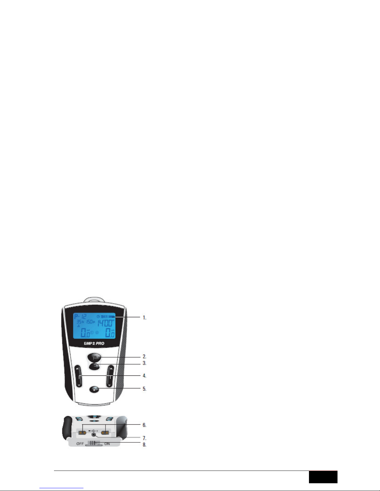
3Operating elements ............................................................................................................... 3
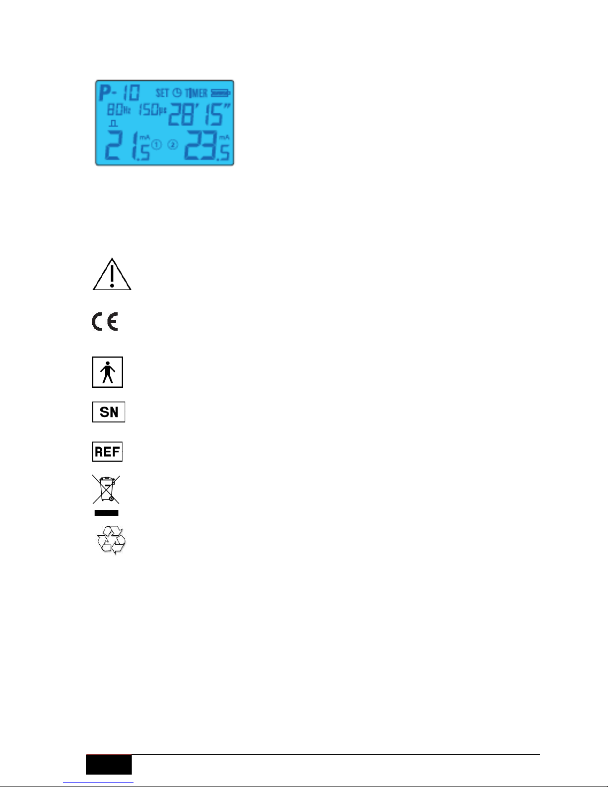
4Description of graphical symbols ........................................................................................... 4
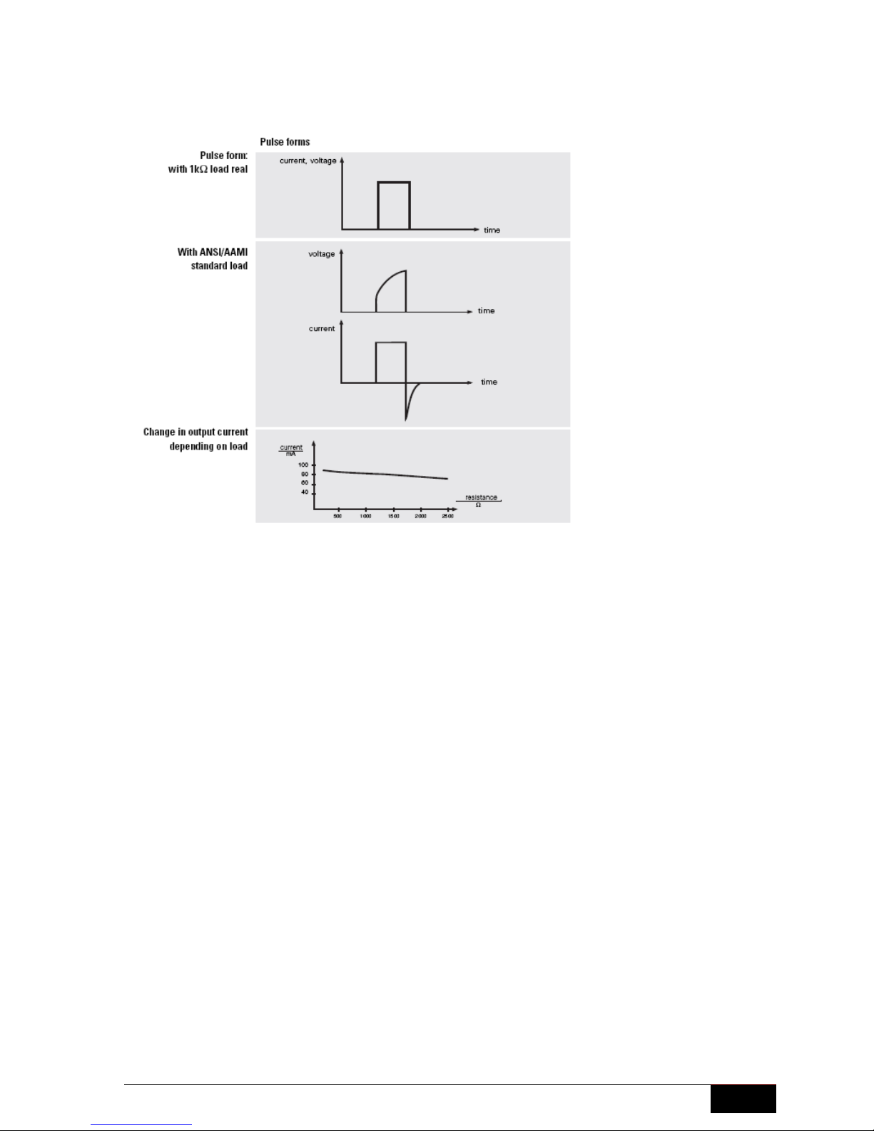
5Technical specification .......................................................................................................... 4
6Operating the EMP 2 PRO .................................................................................................... 5
7Description of the programs .................................................................................................. 6
8User programs (U1 – U21) .................................................................................................. 13
9General information on intensity settings............................................................................. 14
10 General information............................................................................................................. 14
11 Delivery Content.................................................................................................................. 15
12 Accessories......................................................................................................................... 15
13 Electrode placement............................................................................................................ 17
1 Intended use
The EMP 2 PRO has been designed as a device for the generation of transcutaneous electrical
stimulation of nerves and muscles on humans and may not be used for any other purpose.
Please read the operating instructions carefully before using the EMP 2 PRO.
2 Safety instructions
Important safety hints
The EMP 2 PRO is only to be used for stimulation purposes on one patient at a time.
Use the EMP 2 PRO only with original accessories. The size of the electrodes should not be less
than 2 cm². The electrodes should be positioned in such a way that the current flow will not cross
the heart.
Keep the EMP 2 PRO away from water or other liquids. Do not drop the EMP 2 PRO, do not use
it inappropriately or expose it to extreme temperatures or high levels of humidity (not less than
10°C or more than 40°C or a relative humidity of more than 90 %).
Do not use the EMP 2 PRO if it is not working properly or if it has been damaged in any way.
Be careful when using the EMP 2 PRO near or on children. Keep the unit away from children.
Always store the EMP 2 PRO in its case to protect it from damage and dust.
To avoid reciprocal interference, the EMP 2 PRO should not be operated in the vicinity of other
electronic devices. If this is not possible, the various unit functions should be closely monitored
during operation so that proper use in accordance with the regulations is ensured. The
simultaneous connection to the patient of a high frequency surgery unit can lead to skin burning
under the electrodes or around the probe. Operating close (1m) to short wave and microwave
units or mobile telephone systems can cause fluctuations in the output values of the electric
current stimulation unit.
Do not use the machine during the simultaneous operation of other machines when driving or
when asleep.

EMP2 PRO | Instruction Manual
3
Contra-indication
Check with your physician before using the EMP 2 PRO if one of these points applies to you:
•Patients with electronic implants such as heart pacemakers, defibrillators or pumps
•Patients with cardiac rhythm disorders
•During pregnancy
•Patients subject to seizure disorder / epilepsy
•Patients with skin disorders in the vicinity of the electrodes
•Patients with malignant diseases in the region of application
Side effects
•Pain caused by the stimulation: The stimulation can be perceived as uncomfortable/painful if
the electric current is too intensive or if the electrodes have been positioned unfavorably.
Unpleasant side effects can be avoided by adjusting the intensity, using another program with
other parameters and the possible re-positioning of the electrodes.
•Skin intolerance which can result from the electrodes, electrode gel or electric current
impulses. The physician should be consulted in cases of reddening, burning, itching or
blistering under the electrodes or in the vicinity of the electrodes. Slight skin reddening of
short duration in the area of the electrodes following stimulation is quite normal because
blood circulation has been improved by the effects of the stimulation.
•Muscular pain: If the stimulation has been too intense or too long muscular aches in terms of
sore muscle can occur. Shorten the treatment time and the intensity of stimulation at the
beginning of muscle stimulation to avoid muscle ache.
3 Operating elements
The EMP 2 PRO has been designed for the generation of nerve and muscle stimulation on
human beings. All parameters can be adjusted via the press keys and are indicated on the large
display.
1. Display
2. Menu key (Program choice)
3. Keys to enter the programming mode
4. Modification keys to adjust parameters
and to modify the intensity
5. ON/OFF key
6. Output sockets for the cables
7. Output socket for the battery charger
8. ON/OFF commutator

4 EMP2 PRO | Instruction Manual
4 Description of graphical symbols
Label symbols
Attention: Read accompanying documents, especially user manual!
0197
By labelling with CE certificate, the manufacturer states that the product
meets all active requirements of the regarding EU Directive. A conformation
evaluation process has been successfully completed. The code number of
the conformation evaluation process is given in accordance with the CE
labelling of the involved notified body.
BF type application part. Protection against electric shocks.
The serial number of the product follows this symbol.
The article or order number of the product follows this symbol.
This equipment is marked with the recycling symbol. You must dispose of it
separately at an appropriate collection point and not place it in the normal
domestic unsorted stream.
NiMH
This product works with a NiMH rechargeable battery. This battery is reusable. You must
dispose of it properly depending on the laws and regulations of your country.
5 Technical specification
Two-channel nerve and muscle stimulator with electrically insulated channels, constant current
characteristic, Output Short Circuit for skin protection (AKS), 21 integrated pre-set programs and
21 user programs.
Output current : 100 mA (with an actual resistor of 1 kΩ)
Frequency range: 1-120 Hz
Impulse width: 50-500 µs
Nominal current: 3 mA
Power supply: integrated rechargeable battery Ni-MH 4.8 V
The display shows :
- The program number: P 10
- The battery level: full
- The set parameters: 80 Hz, 150 µs
- The remaining therapy time: 28 minutes and 15 seconds
- The intensity used: 21.5 mA on channel 1
and 23.5 mA on channel 2

EMP2 PRO | Instruction Manual
5
Dimensions/Weight: 115 x 65 x 28 mm/ approx. 145 g
6 Operating the EMP 2 PRO
Switching-ON the EMP 2 PRO
Charge the battery of the EMP 2 PRO before first use. Switch the commutator (no. 8) to the ON
position. Switch on the unit by pressing the key (no. 5). The program shown on the display is
the last which was used during the previous session. If the display shows a key symbol on the
upper left side, the EMP 2 PRO has previously interlocked a specific program (see chapter
locking the key pad).
Selecting a program
Select a program by pressing the Pkey (no. 2). To scroll through the programs, press the Pkey
as often as necessary until you have selected the program of your choice. To return to the
previous program, press the left ▼key (no. 4). Selecting a program is only possible if the keypad
has not been locked on one specific program (see chapter locking the key pad).
Connect cables and electrodes
Connect the electrodes with the cable(s) (always 2 electrodes per cable). Connect the cable(s) to
the EMP 2 PRO (no. 6). Place the electrodes on the desired area (see examples on chapter
Electrode placement). Always follow the recommendation of the therapist.
Starting the stimulation and setting the intensity
Start the stimulation by increasing the intensity with the ▲key (no. 4) of the channel(s)
connected to the electrodes.
▲key to increase the intensity
▼key to decrease the intensity

6 EMP2 PRO | Instruction Manual
The intensity of each channel is displayed on the screen. The intensity can be set between 0 and
100 mA. By keeping the intensity keys pressed, the intensity will increase/decrease more rapidly.
Caution!
The stimulator automatically locks the intensity to the set level after 5 seconds. To adjust the
intensity you firstly need to decrease the intensity. The intensity can then be increased again.
If electrodes are connected not or not correctly to the stimulator, you will not be able to set the
intensity to more than 10 mA. The same result will occur if electrodes are old or the cables
broken.
Terminating the stimulation
You can stop the stimulation at any time by pressing the Pkey or the key for 2 seconds.
When the therapy time is completed the stimulation terminates automatically.
If you press the key for one second the EMP 2 PRO switches off.
Lock the key pad
Choose the desired program by pressing the P key (see chapter select a program). Press
simultaneously for 3 seconds the right ▼key and the Pkey to lock the stimulator on the chosen
program before starting the stimulation. The EMP 2 PRO can now only be used with the chosen
program. A key symbol appears on the display next to the program number. All keys except the
intensity and the ON/OFF keys are locked into this mode. Use the same key combination to
unlock the stimulator.
Switch-OFF the buzzer
Press the left ▼key and the Pkey to enter the buzzer mode. Press the E key to switch the
buzzer OFF. Press the E key a second time to turn it ON again. Press the key to exit the
buzzer mode.
Switch-OFF the stimulator
Press the key for one second and release the key just after it to turn the EMP 2 PRO OFF. If
the battery level is too low or if the stimulator has not been used for the previous 2 minutes, it
turns off automatically.
Charging the battery
The battery level is shown on the display with a battery symbol with 4 lines. If the battery level is
too low, the stimulator switches off automatically and cannot be turned on again. The battery then
needs to be re-charged.
- Switch the commutator to the OFF position (no. 8)
- Connect the charger with the EMP 2 PRO (socket no. 7)
- Connect the charger to the mains circuit. The diode on the charger illuminates in red.
- Charge the EMP 2 PRO until the diode on the charger illuminates in green. The battery is
fully charged if the light on the charger appears in green.
- Plug the charger off the mains circuit and plug off the unit from the charger.
- Do not forget to switch the commutator ON again after charging.
Important! Do not charge the EMP 2 PRO for more than 4 hours.
7 Description of the programs

EMP2 PRO | Instruction Manual
7
Factory settings
The parameters from P1 to P21 are identical in new devices to respectively U1 to U21
Program P1 and U1 Low back pain
Stimulation type Slow dynamic stimulation
Frequency channel 1 and 2 80 Hz Pulse width 150 µs
Rising ramp 1 s Falling ramp 1 s
Therapy duration 20 min
Description Both channels are working with the same frequency. Each channel
is working time delayed to the other. The intensity increases within 1 s from zero to the set level
and decreases within 1 s from the set level back to zero. Since both channels work in phase,
channel 1 reaches its maximum intensity level when channel 2 is at its lowest intensity level.
Dynamic stimulation offers a comfortable massage-effect and pain relief when electrodes are
placed in the right position in the pain area. Please see the special electrodes settings for
dynamic stimulation in the chapter electrode placement.
Symbols on the display during stimulation:
Rising ramp: Falling ramp:
Program P2 and U2 Lumbosciatica
Stimulation type Channel 1: Gate control 80 Hz
Channel 2: Endorphin release 2 Hz
Frequency channel 1 80 Hz Pulse width 200 µs
Frequency channel 2 2 Hz Pulse width 200 µs
Therapy duration 20 min
Description: Program 2 works with 2 different frequencies on each channel.
Channel 1 works in gate control mode and channel 2 in endorphin release mode.
Symbol on the display during stimulation:
Program P3 and U3 Cervico-brachial neuralgia
Stimulation type Fast dynamic stimulation
Frequency 80 Hz Pulse width 150 µs
Rising ramp 0.2 s Falling ramp 0.2 s
Therapy duration 20 min
Description: Both channels are working with the same frequency. Each channel
is working time delayed to the other. The intensity increases within 0.2 s from zero to the set level
and decreases within 0.2 s from the set level back to zero. Since both channels work in phase,
channel 1 reaches its maximum intensity level when channel 2 is at its lowest intensity level.
Dynamic stimulation offers a comfortable massage effect and pain relief when electrodes are

8 EMP2 PRO | Instruction Manual
placed in the right position in the pain area. Please see the special electrodes settings for
dynamic stimulation in the chapter “electrode placement”.
Symbols on the display during stimulation:
Rising ramp: Falling ramp:
See illustration program no. 1
Program P4 and U4 Chronic pain
Stimulation type Burst
Frequency 100 Hz Pulse width 150 µs
Working phase 0.25 s Pause 0.25 s
Therapy duration 20 min
Description: Program 4 produces a series of impulse packages with 100 Hz for
0.25 s and then pauses the stimulation for 0.25 s. The high frequency impulses (100 Hz) are
produced in a low frequency rhythm (2 Hz carrier frequency). Program 4 is a good alternative for
chronic pain patients who want to try other kinds of parameters.
Symbols on the display during stimulation:
Working phase: Pause:
Program P5 and U5 Gate control + endorphin release
Stimulation type Channel 1: Gate control
Channel 2: Endorphin release
Frequency channel 1 100 Hz Pulse width 200 µs
Frequency channel 2 2 Hz Pulse width 200 µs
Therapy duration 20 min
Description: Program 5 works with 2 different frequencies on each channel.
Channel 1 works in gate control mode and channel 2 in endorphin release mode.
Symbol on the display during stimulation:
See illustration program no. 2
Program P6 and U6 Gonarthrosis / Coxarthrosis
Stimulation type HAN
Phase 1: Phase 2:
Frequency 100 Hz 2 Hz
Pulse width 200 µs 200 µs

EMP2 PRO | Instruction Manual
9
Working phase 3 s 3 s
Therapy duration 20 min
Description: Program 6 alternates between 3 s of high frequency stimulation and
3 s of low frequency stimulation. This program combines the effect of gate control with the effect
of endorphin release. Program 6 shows good relief for arthrosis pain but can also be used for any
other kind of pain.
Symbols on the display during stimulation:
Phase 1: Phase 2:
Program 7 and U7 Epicondylitis
Stimulation type Modulation
Minimum frequency 2 Hz Maximum frequency 80 Hz
Pulse width 178 µs Pulse width 100 µs
Modulation duration 7.5 s
Therapy duration 20 min
Description: The frequency continuously changes within the modulation range: it
increases from 2 Hz to 80 Hz in 7.5 s and decreases from 80 Hz to 2 Hz in 7.5 s. The pulse width
adapts automatically within the range of 200 µs at the lowest frequency and 100 µs at the highest
frequency. Program 7 suits well for patient with chronic epicondylitis but also patients who are
using TENS for a long time and need an alternative to the previous parameters.
Symbols on the display during stimulation:
Rising ramp: Falling ramp:
Program 8 and U8 Algodystrophy
Stimulation type Modulation
Minimum frequency 2 Hz Pulse width 148 µs
Maximum frequency 80 Hz Pulse width 70 µs
Duration of the modulation 7.5 s
Therapy duration 20 min
Description: The frequency continuously changes within the modulation range: it
increases from 2 Hz to 80 Hz in 7.5 s and decreases from 80 Hz to 2 Hz in 7.5 s. The pulse width

10 EMP2 PRO | Instruction Manual
adapts automatically within the range of 148 µs at the lowest frequency and 70 µs at the highest
frequency. Program 8 and program 7 differentiate in the pulse width range.
Symbols on the display during stimulation:
Rising ramp: Falling ramp:
See illustration program no. 7
Program 9 and U9 Gate control anti-adaptation
Stimulation type Dynamic stimulation
Frequency 80 Hz Pulse width 150 µs
Rising ramp 0.5 s Falling ramp 0.5 s
Therapy duration 20 min
Description: Both channels are working with the same frequency. Each channel
is working time delayed to the other. The intensity increases within 0.5 s from zero to the set level
and decreases within 0.5 s from the set level back to zero. Since both channels work in phase,
channel 1 reaches its maximum intensity level when channel 2 is at its lowest intensity level.
Dynamic stimulation offers a comfortable massage effect and pain relief when electrodes are
placed in the right position in the pain area. Please see the special electrode positioning for
dynamic stimulation in the chapter electrode placement.
Symbols on the display during stimulation:
Rising ramp: Falling ramp:
See illustration program no. 1
Program 10 and U10 Classic gate control
Frequency 120 Hz Pulse width 150 µs
Therapy duration 20 min
Description: Program 10 works with the same frequency and pulse width on both
channels. It suits best for acute pain (nerve pain as well as joint pain).
Symbol on the display during stimulation:
Program 11 and U11 Treatment of contractures
Frequency 1 Hz Pulse width 150 µs
Therapy duration 20 min
Description: Program 11 suits well for the treatment of contractures as well as for
the treatment of chronic pain.
Symbol on the display during stimulation:
See illustration program no. 10
Program 12 and U12 Atrophy upper extremities
Stimulation type Muscle strengthening

EMP2 PRO | Instruction Manual
11
Frequency 35 Hz Pulse width 150 µs
Rising ramp 2 s Working phase 3 s
Falling ramp 1 s Pause 9 s
Therapy duration 20 min
Rising ramp: Falling ramp: Pause:
Program 13 and U13 Atrophy lower extremities
Stimulation type Muscle strengthening
Frequency 35 Hz Pulse width 300 µs
Rising ramp 2 s Working phase 3 s
Falling ramp 1 s Pause 9 s
Therapy duration 20 min
Rising ramp: Falling ramp: Pause:
See illustration program no. 12
Program 14 and U14 Muscle strengthening upper extremities
Stimulation type Muscle strengthening
Frequency 65 Hz Pulse width 250 µs
Rising ramp 2 s Working phase 4 s
Falling ramp 1 s Pause 8 s
Therapy duration 20 min
Rising ramp: Falling ramp: Pause:
See illustration program no. 12
Program 15 and U15 Muscle strengthening lower extremities
Stimulation type Muscle strengthening
Frequency 65 Hz Pulse width 300 µs
Rising ramp 2 s Working phase 4 s
Falling ramp 1 s Pause 8 s
Therapy duration 20 min
Rising ramp: Falling ramp: Pause:
See illustration program no. 12
Program 16 and U16 Venous reflux
Frequency 35 Hz Pulse width 250 µs
Rising ramp 3 s Working phase 5 s
Falling ramp 1 s Pause 10 s
Therapy duration 20 min
Rising ramp: Falling ramp: Pause:
See illustration program no. 12
Program 17 and U17 Urge incontinence
Frequency 10 Hz Pulse width 180 µs
Therapy duration 15 min

12 EMP2 PRO | Instruction Manual
Description: The urge to pass water often occurs when only minimal amounts of
urine are present in the bladder; this can lead to premature release. The cause of urge
incontinence is an over-active bladder musculature, usually triggered by the nervous system.
Symbol on the display during stimulation:
See illustration program no. 10
Program 18 and U18 Mixed incontinence
Frequency 20 Hz Pulse width 180 µs
Rising ramp 2 s Working phase 4 s
Falling ramp 1 s Pause 4 s
Therapy duration 15 min
Description Mixed incontinence is a mix of stress and urge incontinence.
Symbols on the display during stimulation:
Rising ramp: Falling ramp: Pause:
See illustration program no. 12
Program 19 and U19 Stress incontinence
Frequency 50 Hz Pulse width 180 µs
Rising ramp 2 s Working phase 3 s
Falling ramp 1 s Pause 6 s
Therapy duration 15 min
Description Stress-related incontinence is caused by a disorder in the urethral
closure system, for the most part by untrained or over-elongated pelvic floor muscles, for
example as a result of difficult child-births. For women, an age-related lack of hormones can be a
contributory factor.
Symbols on the display:
Rising ramp: Falling ramp: Pause:
See illustration program no. 12
Program 20 and U20 Dynamic stimulation slow
Stimulation type Dynamic stimulation
Frequency 120 Hz Pulse width 150 µs
Rising ramp 2 s Falling ramp 2 s
Therapy duration 20 min
Description Both channels are working with the same frequency. Each channel
is working time delayed to the other. The intensity increases within 2 s from zero to the set level
and decreases within 2 s from the set level back to zero. Since both channels work in phase,
channel 1 reaches its maximum intensity level when channel 2 is at its lowest intensity level.
Dynamic stimulation provides a comfortable massage effect and pain relief when electrodes are
placed in the right position in the pain area. Please see the special electrode positioning for
dynamic stimulation in the chapter electrode placement.

EMP2 PRO | Instruction Manual
13
Symbols on the display during stimulation:
Rising ramp: Falling ramp:
See illustration program no. 1
Program 21 and U 21 Agonist / Antagonist
Stimulation type Dynamic stimulation ; channel 1 and channel 2
Frequency 40 Hz Pulse width 300 µs
Rising ramp 2 s Falling ramp 1 s
Work phase 3 s Pause 6 s
Therapy duration 20 min
Description channel 1 stimulate the agonist and channel 2 the antagonist
time delayed
Symbols on the display:
Rising ramp: Falling ramp: Pause:
8 User programs (U1 – U21)
Create a user program
Switch ON the EMP 2 PRO. Select a USER program with the Pkey (U1 – U21). Press the Ekey
to access the editing mode. The parameters to be changed are flashing on the display. Adjust the
flashing parameter with the ▼and ▲keys. Press the Ekey to save your changes and to access
the next parameters. Repeat the operation for all parameters (frequency, pulse width, therapy
duration and ramp/pause time). Press the Ekey at the end to save your changes.
Description of user program possibilities
Program U1, U3, U4, U9, U20: Dynamic stimulation
Frequency: 20 Hz -120 Hz
Pulse width: 70 µs - 500 µs
Stimulation time: 1 - 99 min.
Program U2, U5: TENS
Channel 1: gate control / Channel 2: Endorphin release
Frequency channel 1: 80 Hz, 90 Hz, 100 Hz, 110 Hz, 120 Hz
Frequency channel 2: 2 Hz, 5 Hz, 10 Hz
Pulse width: 70 µs - 500 µs
Stimulation time: 1 - 99 min.
Program U6: HAN
Stimulation time: 1 - 99 min.
Program U7, U8 : Modulation
Max. frequency: 10 Hz - 120 Hz
Min. frequency: 2 Hz, 3 Hz, 4 Hz, 5 Hz, 6 Hz, 7 Hz, 8 Hz
Pulse width: 70 µs - 180 µs
Stimulation time: 1 - 99 min.

14 EMP2 PRO | Instruction Manual
Program U10, U11, U17: TENS
Frequency: 20 Hz - 120 Hz
Pulse width: 70 µs - 500 µs
Stimulation time: 1 - 99 min.
Program U12, U13, U14, U15, U16, U18, U19,U21: Muscle stimulation
Frequency: 20 Hz - 120 Hz
Pulse width: 70 µs - 500 µs
Rising ramp: 1 - 4 s
Work phase: 1 - 25 s
Falling ramp: 1 s
Pause: 1 - 25 s
Stimulation time: 1 - 99 min. (Fig. 12)
9 General information on intensity settings
Do not try to achieve a too high level of intensity. Set the intensity in such a way that you get a
comfortable feeling during the stimulation. Increase the intensity carefully to a tolerable
maximum, and then reduce it slightly step by step to a comfortable level. Please note that the
intensity settings change depending on the stimulation area and time. This is normal and can be
explained as follows:
Resistance of the skin: Dry skin has a lower conductivity level than wet skin (due to sweating).
The skin does not show the same resistance to linear current on all parts of the body. For
example, the resistance level of horny skin can be twice that of the skin in the hollow of the knee.
The innervation differs greatly according to the area of the body. This results in a difference of
sensitivity.
Volume of the muscle mass: If you stimulate muscles with a high volume you will automatically
need to set a higher intensity than for the stimulation of small muscles.
Muscle fatigue: A tired muscle will only tolerate a lower intensity.
Age of electrodes: Self-adhesive electrodes do not last forever. The number of use depends on
the quality of the electrodes but also on the skin of the user. Old electrodes have a higher
resistance and their conductivity levels decline. It is important to replace electrodes regularly.
Adaption to the current: The nerves adapt rapidly to the current. It is normal to feel “less
current” after a few minutes of stimulation with specific parameters. In such a case feel free to
increase the intensity in order to get the best results.
Frequency and pulse width: Frequencies and pulse widths differ depending on the program.
Therefore the intensity cannot be set at the same level for all the programs even if the electrodes
are placed in the same position. The higher the frequency is set, the lower you will be able to set
the intensity. The higher the pulse width is set, the lower you will be able to set the intensity.
10 General information
Adjustments, modifications and repairs
The manufacturer is only responsible for the safety and performance of the EMP 2 PRO when
readjustments, alterations and repairs are carried out by authorized persons and when the EMP 2
PRO is used in accordance with the operating instructions.

EMP2 PRO | Instruction Manual
15
Warranty
Legal right of warranty is applied according to German Civil Code.
Guarantee
The manufacturer issues a guarantee of 12 months from the date of purchase.
The guarantee does not apply in the following cases:
• damage due to improper handling
• defects the customer is aware of on the date of purchase
• damage caused by the customer
• for wearing parts and consumable supplies like, for instance, battery, cables and electrodes.
Maintenance and cleaning
No special cleaning or care agents are required for the EMP 2 PRO. Clean the stimulator with a
soft, lint-free cloth. Please ensure that no moisture permeates the stimulator. If moisture does
permeate the stimulator, a technical check must be carried out before re-use.
Classification
The EMP 2 PRO has been designed as a class IIa product in accordance with appendix IX of the
Medical Device Directive 93/42/EEC.
Technical check
We recommend a technical check on the EMP 2 PRO every 24 months. This includes:
1. Confirming that user instructions have been included in the accompanying documentation.
2. Checking the equipment for completeness.
3. Visual check:
- for mechanical damage
- for damage to all cables and plugs / sockets
4. Functional Safety
- Checking the output signals with a load resistance of 1 kΩreal current and voltage
- Checking the frequency
- Checking the pulse width
These technical checks may only be performed by suitably qualified persons. The results must be
documented with the date and name of the person carrying out the check.
11 Delivery Content
Art. no. Article Quantity
104068 EMP 2 PRO 1
450781-0025 Integrated battery 1
106351 Cable type 5.15 2
283400 Self-adhesive electrodes 50x50 mm (4 pieces) 1
101062 Charger WK 112 1
101674 Instruction manual 1
12 Accessories
The EMP 2 PRO may only be used together with all accessories named below. The manufacturer
cannot guarantee the security of the stimulator if not used with original accessories.
Stimex self-adhesive electrodes
Art. No. Description Quantity

16 EMP2 PRO | Instruction Manual
281000 Stimex 32 mm round 4
282000 Stimex 50 mm round 4
283400 Stimex 50x50 mm 4
281032 Stimex 50x50 mm 20
283600 Stimex 50x90 mm 2
283000 Stimex 50x130 mm 2
283100 Stimex 80x130 mm 2
281027 Stimex sensitive 50x50 mm 4
Silicone electrodes (to be used with contact gel)
Art. No. Size Quantity
107090 20 mm round 2
107011 38x45 mm 2
107010 48x48 mm 2
107050 70x65 mm 2
108000 contact gel (tube, 60 g) 1
Garment electrodes: gloves and socks
Stimex electrode gloves and socks used in combination with
a schwa-medico electrotherapy unit are ideal for home treatment.
They provide stimulation of the entire hand and/or foot and ankle
and avoid the sometimes tiresome attachment of self-adhesive
electrodes to the hand or foot.
Gloves
Art. No. Article Size Pieces
107014 Stimulation gloves S 1 pair
107021 Stimulation gloves M 1 pair
107022 Stimulation gloves L 1 pair
Socks
Art. No. Article Size Pieces
107023 Stimulation socks M 1 pair
107024 Stimulation socks L 1 pair
MedicoBack P-Type
Low back support bandage with pelotte and integrated electrodes to be used with the EMP 2
PRO.
MedicoBack P-type offers patients lumbar vertebrae stabilization and support as well as easy
nerve stimulation thanks to the integrated electrodes. The pelotte with its massage nubs
intensifies the pain relieving effect. MedicoBack P-type may be used for light or acute pain as well
as for chronic pain in the lower back area.
Art. No. Article Size Length
107034 MedicoBack P-type S 80-90 cm
107036 MedicoBack P-type M 90-100 cm
107037 MedicoBack P-type L 100-110 cm
107038 MedicoBack P-type XL 110-120 cm
107039 MedicoBack P-type XXL 120-130 cm
MedicoBack P-Type is including:

EMP2 PRO | Instruction Manual
17
1 low back support bandage
1 pelotte
1 cover for the pelotte
with integrated electrodes
1 cover for the pelotte
without integrated electrodes
8 gel pads
13 Electrode placement
Electrode placement for pain treatment
Back pain

18 EMP2 PRO | Instruction Manual
Shoulder pain
Epicondylitis ulnaris Epicondylitis radialis
Arthrosis (hip) Kaada (one channel use)
Sciatic pain
Gonarthrosis/Knee pain Ankle joint pain

EMP2 PRO | Instruction Manual
19
Trigeminus neuralgia
Migraine Tension headache
Polyarthritis / Polyneuropathy

20 EMP2 PRO | Instruction Manual
Carpal tunnel syndrome Pain of Achilles’ tendon/heel pain
Electrode placement for dynamic stimulation
The stimulation is not administered simultaneously on both channels. The current flows from one
electrode to the other like a wave on the body. This kind of stimulation is far more comfortable
than traditional neuro-muscular stimulation. Dynamic stimulation can be used with high frequency
parameters for an improved pain control or with low frequency parameters for optimized muscle
stimulation. This treatment method also has an enhanced effect on lymphatic drainage
stimulation. The placement of electrodes for dynamic stimulation depends on the direction of
stimulation (rising/falling stimulation or sideways stimulation)
Rising or falling stimulation Sideways stimulation
for back or legs for gluteus muscle or stomach muscle
Other manuals for EMP 2 PRO
1
Table of contents
Other schwa-medico Fitness Electronic manuals