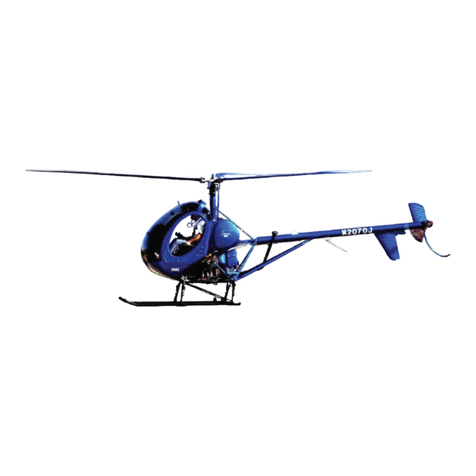
Schweizer 300CB Technical specifications

SCHWEIZER AIRCRAFT CORP.
Supplement to the Approved
Rotorcraft Flight Manual
For
Schweizer 300CB Helicopter
Model 269C-1
INSTRUMENT/AVIONICS INSTALLATIONS
1
CSP-C1-1A
Date of Original Approval: October 3, 1995
Date of Rev. #9 Approval:
Approved By: Acting Manager, Flight Test and
Systems Branch, NYACO, ANE-172

Log of Pages
PAGE DATE PAGE DATE
1 29 Mar 2001 19 17 Apr 1996
2 29 Mar 2001 20 17 Apr 1996
3 29 Mar 2001 21 17 Apr 1996
4 03 Oct 1995 22 17 Apr 1996
5 29 Mar 2001 23 17 Apr 1996
6 29 Mar 2001 24 17 Apr 1996
7 23 Jul 1999 25 17 Apr 1996
7.1 23 Jul 1999 26 17 Apr 1996
7.2 23 Jul 1999 27 17 Apr 1996
8 17 Apr 1996 28 17 Apr 1996
9 17 Apr 1996 29 17 Apr 1996
10 17 Apr 1996 30 17 Apr 1996
10.1 29 Mar 2001 31 21 May 1997
10.2 29 Mar 2001 32 09 Jan 1998
10.3 29 Mar 2001 33 23 Jul 1999
10.4 29 Mar 2001 34 23 Jul 1999
11 17 Apr 1996 35 23 Jul 1999
12 17 Apr 1996 36 02 Mar 2001
13 17 Apr 1996 37 20 Feb 2001
14 21 May 1997 38 20 Feb 2001
15 21 May 1997 39 20 Feb 2001
16 17 Apr 1996 40 20 Feb 2001
17 17 Apr 1996
18 17 Apr 1996
SCHWEIZER MODEL 269C-1 HELICOPTER
CSP-C1-1A
2 FAA Approved: 03 Oct 1995
Revised: 29 Mar 2001
NOTES
The change bar ( ) defines the latest FAA Approved
changes. The asterisk (*) indicates not officially approved.

SCHWEIZER MODEL 269C-1 HELICOPTER
CSP-C1-1A
FAA Approved: 03 Oct 1995 3
Revised: 29 Mar 2001
REVISION TABLE
Number Date Description
#1
#2
#3
#4
#5
#6
#7
#8
#9
04 Dec 1995
17 Apr 1996
21 May 1997
09 Jan 1998
23 Jul 1998
20 Feb 2001
02 Mar 2001
29 Mar 2001
Revised to include KX 155, KI 203
and KI 208.
Revised to include KX 165, “Hot
Mic”, Transfer/Channel Increment
Switch, KR87, KR 21, KMA 24H,
KI 229, KN 62A, KCS55A and
Avionics Master Switch.
Revised to include KI209 Indicator
and Transmitter/Receiver, Audio
Monitor Selector Switch and
miscellaneous other changes.
Revised to include GNC
250/250XL Comms/GPS.
Never Issued.
Revised to include GPS 150, GPS
150XL and KLN 89B GPS.
Revised to include GPS 430
COMM/NAV/GPS.
Revised to include GTX 320 Tran-
sponder
Revised to include GTX 320A and
GTX 327 Transponder

This page is intentionally left blank.
SCHWEIZER MODEL 269C-1 HELICOPTER
CSP-C1-1A
4 FAA Approved: 03 Oct 1995
Revised: 02 Mar 2001

SCHWEIZER MODEL 269C-1 HELICOPTER
CSP-C1-1A
FAA Approved: 03 Oct 1995 5
Revised: 29 Mar 2001
Table Of Contents
Section/
Para Number Title
Section I Introduction and General
Section II Limitations
Section III Emergency and Malfunction Procedures
Section IV Normal Procedures
4.1 KY 96A/196A VHF Comm. Transceiver
4.2 KT 76A Transponder
4.2B GTX 320/320A Transponder
4.2C GTX 327 Transponder Oper. Instructions
4.3 KX 155/165 VHF NAV/COMM
4.4 Navigation Indicators
KI 203 VOR/LOC Indicator
KI 208 VOR/LOC Indicator
KI 209 VOR/LOC/GS Indicator
4.5 Switchable “Hot Mic”
4.6 Remote Frequency Transfer/Channel
Increment Switch
4.7 KR 87 ADF
4.8 KI 229 RMI
4.9 KCS 55A Compass System
7
7
7
8
8
10
10.1
10.2
11
14
15
15
15
20
20
Page No.

SCHWEIZER MODEL 269C-1 HELICOPTER
CSP-C1-1A
6 FAA Approved: 03 Oct 1995
Revised: 29 Mar 2001
Section IV Normal Procedures (Cont)
4.10 KN 62A DME
4.11 KMA 24H Audio Panel
4.12 KR 21 Marker Beacon
4.13 Avionics Master Switch
4.14 Transmitter/Receiver and Audio Monitor
Selector Switches
4.15 GNC 25/250XL
4.16 GPS 150
4.17 GPS 150XL
4.18 KLN 89B GPS
4.19 GNS 430 COMM/NAV/GPS
Section V Performance Data
Section VI Weight & Balance
Section VII Aircraft Handling, Service & Maintenance
Section VII Additional Operations & Performance Data
Table Of Contents
Section/
Para Number Title
8
25
27
30
30
32
33
34
35
37
39
40
40
40
Page No.

SECTION I
Introduction and General
This supplement contains basic operating instructions for avionics and
instrumentation which may be installed on the aircraft. As installed
equipment varies with each aircraft, it is the pilot’s responsibility to
become familiar with the operation and function of all installed equipment.
This supplement must be carried in the applicable basic FAA approved
300CB Model 269C-1 Rotorcraft Flight Manual when the rotorcraft is
equipped with any of the instruments or avionics whose operation is
contained herein.
Except as modified by this flight manual supplement, operation in
compliance with the basic approved Rotorcraft Flight Manual is mandatory.
SCHWEIZER MODEL 269C-1 HELICOPTER
CSP-C1-1A
FAA Approved: 03 Oct 1995 7
Revised: 23 Jul 1999

SECTION II
Limitations
The installation of the equipment listed in this supplement is for VFR
aircraft, only, and does not make the aircraft eligible for flight into IFR or
IMC conditions.
If this aircraft has an installed GPS Navigation System, a placard (Garmin
P/N 161-00024-00, S.A.C. P/N 269A4646-265, or equivalent) stating “GPS
limited to VRF use only” must be installed in clear view, and be easily
readable by the pilot.
If this aircraft has an installed GPS Navigation System, the GPS
manufacturer’s operation manual must be immediately available to the
flight crew.
SCHWEIZER MODEL 269C-1 HELICOPTER
CSP-C1-1A
7.1 FAA Approved: 03 Oct 1995
Revised: 23 Jul 1999

SECTION III
Emergency and Malfunction Procedures
In case of electrical system failure, all unnecessary electrical equipment
should be turned “OFF” to conserve battery power.
Specific emergency procedures for avionics are provided in the individual
operating instructions where applicable.
SCHWEIZER MODEL 269C-1 HELICOPTER
CSP-C1-1A
FAA Approved: 03 Oct 1995 7.2
Revised: 23 Jul 1999

SECTION IV
Normal Procedures
The pilot’s cyclic stick pistol grip incorporates a three position “trigger”
switch. When the “trigger” switch is pulled to the first detent, the plot’s
microphone is connected to the aircraft intercom (ICS) system. When the
“trigger” switch is pulled through the first detent into the second detent, the
pilot’s microphone is connected to the radio transmitter and the radio
transmitter is “keyed” to transmit. When the “trigger” switch is released, it
returns to the “off” position.
If the aircraft is equipped with dual controls, the “trigger” switch on the
co-pilot’s cyclic stick pistol grip operates the same as the “trigger” switch
on the pilot’s cyclic stick, except the co-pilot “trigger” switch controls the
co-pilot’s microphone.
An optional floor mounted “ICS-XMIT” foot activated switch may be
installed. When the footswitch is depressed on the side placarded “ICS”,
the crewmember with the footswitch, has his microphone connected to the
aircraft intercom system. When the footswitch is depressed on the side
placarded “XMIT”, the crewmember with the footswitch, has his
microphone connected to the radio transmitter and the radio transmitter is
“keyed” to transmit.
The aircraft is provided with headset plug-ins for all crew members. These
plug-ins are hanging cords and are located between the pilot and co-pilot
seats near the top of the seatbacks. The pilot’s plug-in is a plain cord. The
co-pilot plug-in includes a plastic box, (with a clothing clip for attaching to
shirt pocket, etc.) an “ICS” momentary activation switch (for access to the
intercom system) and a coiled cord.
CAUTION
AVIONICS SHOULD BE TURNED ON ONLY
AFTER ENGINE STARTUP. THIS IS A SIMPLE
PRECAUTION WHICH HELPS PROTECT THE
SOLID STATE CIRCUITRY AND EXTENDS THE
OPERATING LIFE OF YOUR AVIONICS EQUIP-
MENT.
SCHWEIZER MODEL 269C-1 HELICOPTER
CSP-C1-1A
8 FAA Approved: 03 Oct 1995
Revised: 17 Apr 1996

4.1 KY 96A/196A VHF COMM. TRANSCEIVER
To turn on the radio rotate the Volume (VOL) knob clockwise
from the OFF position. When power is activated the USE and
Standby (STBY) windows will display the frequencies and/or
mode stored in the non-volatile memory before power down.
After activating power, pull the VOL knob out to override the au-
tomatic squelch and rotate the VOL knob to the desired audio
level. Push the VOL knob back in to activate the automatic
squelch.
T R A N S M I T I N D I C A T O R
During Comm transmissions, a TX (KY96A) or a T (KY 196A)
will appear between the USE and STBY windows to indicate that
the transceiver is in the Transmit mode of operation:
KY 96A COMM Transceiver [TSO’d]
MODES OF OPERATION
A. Frequency Mode
Frequency selection is accomplished in the Standby Entry mode by
changing the frequency display in the STBY window of the display
with the tuning knobs, and then transferring the selected frequency
into the USE window by pressing the Transfer button. The larger
tuning knob will increment or decrement the MHZ portion of the
display in 1 MHZsteps with rollover at each band edge (118.000
MHZor 136.975 MHZ). The smaller tuning knob will increment or
decrement the KHZportion of the display in 50 KHZsteps with the
knob pushed in, or in 25 KHZsteps with the knob pulled out.
While in the Standby Entry mode, the transceiver remains tuned to
the frequency displayed in the USE window at all times.
SCHWEIZER MODEL 269C-1 HELICOPTER
CSP-C1-1A
FAA Approved: 03 Oct 1995 9
Revised: 17 Apr 1996

Amplified operating instructions are provided in Bendix-King Pub-
lications No. 006-08431-0002 (KY96A) and No. 006-8438-000
(KY196A).
KY 196A COMM Transceiver [TSO’d]
4.2 KT76A TRANSPONDER
Turn on the KT76A transponder by rotating the function selector
knob to standby (STBY) for approximately 45 seconds, then to ON
or ALT. Rotating the function selector knob to test TST position
will cause the reply light to illuminate if test is successful. The
transponder code is entered by rotating the code control knobs.
During some operations, ATC may request the pilot to IDENT
which will require a momentary depressing of the IDENT push
button on the KT76A transponder. If aircraft is equipped with an
altitude encoder, the transponder function selector knob must be
turned to the ALT position in order to provide altitude reporting to
ATC.
Amplified operating instructions are provided in Bendix-King Pub-
lication No. 006-8244-08.
KT 76A Class 1A Transponder [TSO’d]
SCHWEIZER MODEL 269C-1 HELICOPTER
CSP-C1-1A
10 FAA Approved: 03 Oct 1995
Revised: 17 Apr 1996

4.2B GTX 320/320A TRANSPONDER OPERATING INSTRUCTIONS
Detailed operating instructions can be found in the (GARMIN P/N
190-00133-09) GTX 320/320A Pilot’s Guide. Some highlights of
that pilot’s guide are printed here.
Operation of this transponder will be very familiar to most pilots.
Many pilots will only need to know that the reply light is the little
caret beside the IDENT button, and that the TST function only
tests the reply light. Pressing the IDENT button causes the special
identification pulse to be added to any normal Mode A or Mode C
replies, and it lights the reply light, for 20 seconds. ON provides
only Mode A replies. ALT provides both Mode A and Mode C
(altitude) replies, and is the normal operating mode.
When changing codes in ON or ALT, do not pass through codes
0000 (government), 7500, (hijack), 7600-7677 (COMMunication
failure), or 7700-7777 (EMERGENCY), or it may trigger an auto-
matic alarm, at Air Traffic Control.
SCHWEIZER MODEL 269C-1 HELICOPTER
CSP-C1-1A
FAA Approved: 03 Oct 1995 10.1
Revised: 29 Mar 2001

4.2C GTX 327 TRANSPONDER OPERATING INSTRUCTIONS
Detailed operating instructions can be found in the (GARMIN P/N
190-00187-00) GTX 327 Pilot’s Guide. Some highlights of that
Pilot’s Guide (and the Installation Manual) are printed here.
Many pilots will only need to know that the (Model A) reply code
is usually displayed, and that pressing a number button starts over
writing in a new reply code (left to right). During new code entry,
the CLR button works as a backspace, and the CRSR button can-
cels a partial (less than four number button presses) entry. As ex-
pected, SBY switches the radio ON but allows no replies, ON
starts only Mode A replies, ALT starts both Mode A and C replies,
and OFF switches the transponder OFF (if held in for at least two
seconds). If the helicopter has an optional Avionics Master
Switch, the GTX 327 will remember which mode was selected be-
fore the Avionics Master was switched OFF. There is no TEST
mode to test the reply light because there is no separate reply light;
there is, instead, a circled “R” that shows up on the lower left cor-
ner of the display, for a reply indicator. The IDENT button acti-
vates 18 seconds of IDENT and adds the word “IDENT” to the
upper left corner of the display. The VFR button toggles to and
from a VFR code (usually 1200) from the entered Mode A reply
code that is remembered (even during shut down) until a new code
is four button entered. (The VFR code may be pilot selected, in
the Configuration mode.)
Pressing the FUNC button advances the PRESSURE ALT part of
the display through three different six digit stopwatch type timers:
a FLIGHT TIME duration timer, a similar COUNT UP timer, and a
reverse operating COUNT DOWN timer (that may all be operated
simultaneously), and then back to (encoder) altitude. Use the
CRSR button and six presses of the ten number buttons, to select
the starting time for the count down timer. The START/STOP
button starts or stops (and the CLR button resets) whichever timer
is presently in view. When the COUNT DOWN timer passes zero,
it flashes and continues as a count up timer, and “COUNT
SCHWEIZER MODEL 269C-1 HELICOPTER
CSP-C1-1A
10.2 FAA Approved: 03 Oct 1995
Revised: 29 Mar 2001

DOWN” is replaced by “EXPIRED.” When the PRESSURE
ALT(altitude encoder output) function is displayed, an up or down
arrow will appear, to the right side of “PRESSURE ALT,” when
the helicopter rate of climb exceeds the number of feet per minute
selected in the Configuration mode. This altitude display can be
pilot configured to read flight level, feet or meters.
When changing codes in ON or ALT, do not pass through codes
0000 (government), 7500 (hijack), 7600-7677 (COMMunication
failure), or 7700-7777 (EMERGENCY), or it may trigger an auto
-
matic alarm at Air Traffic Control.
SCHWEIZER MODEL 269C-1 HELICOPTER
CSP-C1-1A
FAA Approved: 03 Oct 1995 10.3
Revised: 29 Mar 2001

This page is intentionally left blank.
SCHWEIZER MODEL 269C-1 HELICOPTER
CSP-C1-1A
10.4 FAA Approved: 03 Oct 1995
Revised: 29 Mar 2001

4.3 KX 155/165 VHF NAV/COMM OPERATION INSTRUC-
TIONS
COMM TRANSCEIVER
Rotate the VOL knob clockwise from the OFF position. Pull the
VOL knob and adjust for desired listening level on the noise being
produced by the receiver. Push the VOL knob back in to actuate
the automatic squelch.
The left portion of the digital display readout is allocated for
COMM USE and STBY frequencies with a “T” between them to
indicate the TRANSMIT mode of operation. Select the desired op-
erating frequency in the STBY display by rotating the incre-
ment/decrement knobs either clockwise or counterclockwise. A
clockwise rotation will increment the frequency while a counter-
clockwise rotation will decrement the frequency. The larger knob
will change the MHZportion of the STBY display. At one
band-edge (118 or 136 MHZ) the following 1MHZchange will
wrap around to the other band-edge. The smaller knob will change
the KHZportion of the STBY display. It will change in steps of
50KHZwhen the knob is pushed in, and 25KHZwhen the knob is
pulled out. The wrap around band-edge is also utilized when in-
crementing or decrementing the KHZportion of the STBY display.
To tune the radio to the desired operating frequency, the desired
frequency must be entered into the STBY display and then the
transfer button must be pushed. This will trade the contents of the
USE and STBY display. The transceiver is always tuned to the
frequency appearing in the USE display. It is therefore possible to
have two different frequencies stored in the USE and STBY dis-
plays and to change back and forth between them at the simple
push of the transfer button. During the transmit mode of opera
-
tion, a “T” will appear between the USE and STBY displays, signi-
fying that the transceiver is in the transmit mode of operation.
A non-volatile memory stores the COMM USE and STBY frequen-
cies on power down. When the unit is turned on again, the COMM
USE and STBY windows will display the same USE and STBY
frequencies that were displayed before power down. If an invalid
frequency is detected in the memory on power up, the COMM USE
and STBY windows will contain "120.00", thus indicating the pres-
ence of an error in the stored frequency.
SCHWEIZER MODEL 269C-1 HELICOPTER
CSP-C1-1A
FAA Approved: 03 Oct 1995 11
Revised: 17 Apr 1996

The right portion of the display is allocated to NAV receiver USE
and STBY/RAD information. The frequency channeling is the
same as the COMM, when operating in the frequency mode.
The NAV increment/decrement knob is located on the right hand
side of the front panel. The larger knob operates in 1MHZsteps
and increments/decrements the STBY/PAD frequency display.
The smaller knob operates in 50KHZsteps. The NAV receiver’s
lower and upper frequency limits are 108.00MHZand 117.95MHZ.
Exceeding the upper limit of frequency band would automatically
return to the lower limit and vice versa.
Note: Only KX 165 has STBY/RAD window; KX 155
has STBY window only and will not give radial infor-
mation.
On the KX 165, when the smaller knob is pulled out, the VOR
bearing is digitally displayed in STBY/RAD window. In the bear-
ing mode, the increment/decrement knobs channel the USE fre-
quency window and depressing the frequency transfer button will
cause the USE frequency to be placed in blind storage and the
STBY frequency (in the blind storage) to be displayed in the USE
window display. In radial mode of operation, the right hand win-
dow of NAV display shows the bearing FROM the station and
when due to weak signals, a digital flag "---", will be displayed in
the radial window. Also, when an ILS frequency is selected, the
digital flag "---" is displayed in the radial window.
On the KX 155, when the smaller knob is pulled out, the incre-
ment/decrement knob channels the USE frequency window and
depressing the frequency transfer button will cause the USE fre-
quency to be placed in blind storage and the STBY frequency (in
the blind storage) to be displayed in the USE window display, a
digital flag "---", will be displayed in the STBY window.
The NAV USE and STBY frequencies are stored in the memory on
power down and return on power up. On power up, if an error is
detected in the stored frequencies, the unit will display 110.00
MHZin both USE and STBY/RAD windows. The unit does not
store the VOR bearing on power down.
SCHWEIZER MODEL 269C-1 HELICOPTER
CSP-C1-1A
12 FAA Approved: 03 Oct 1995
Revised: 17 Apr 1996

When the smaller increment/decrement knob is pushed in, depress-
ing the NAV TRANSFER button will interchange the USE and
STBY/RAD frequencies. The NAV IDENT knob is active in the
pulled out position so that both voice and ident can be heard.
When this knob is pushed in, the ident tone is attenuated. The vol
-
ume of voice/ident can be adjusted by turning this knob.
Note: If dual Nav’s are installed a placard will be lo-
cated on the receiver and on the corresponding NAV in-
dicator to correlate the NAV receiver with the
appropriate NAV indicator.
Amplified operation instructions are provided in Bendix-King Pub-
lication No. 006-8329-03.
KX 155 NAV/COMM Transceiver [TSO’d]
KX 165 NAV/COMM Transceiver [TSO’d]
SCHWEIZER MODEL 269C-1 HELICOPTER
CSP-C1-1A
FAA Approved: 03 Oct 1995 13
Revised: 17 Apr 1996

4 . 4 N A V I G A T I O N I N D I C A T O R S
NAV Indicators for use with the KX 155:
KI 203 VOR/LOC Indicator [TSO’d]
KI 208 VOR/LOC Indicator [TSO’d]
KI 209 VOR/LOC Indicator [TSO’d]
SCHWEIZER MODEL 269C-1 HELICOPTER
CSP-C1-1A
14 FAA Approved: 03 Oct 1995
Revised: 21 May 1997
This manual suits for next models
1
Table of contents
Other Schweizer Toy manuals
Popular Toy manuals by other brands

Eduard
Eduard MiG-23 Flogger armament Assembly instructions

Seagull Models
Seagull Models Extra 260 instruction manual

Emerson
Emerson Nick Jr. Dora the Explorer DTE516 owner's manual

Fisher-Price
Fisher-Price Laugh & Learn First Words Smart Puppy FFN33 manual

Fisher-Price
Fisher-Price Lil Table, Big Fun user guide

Mattel
Mattel P8944 instructions