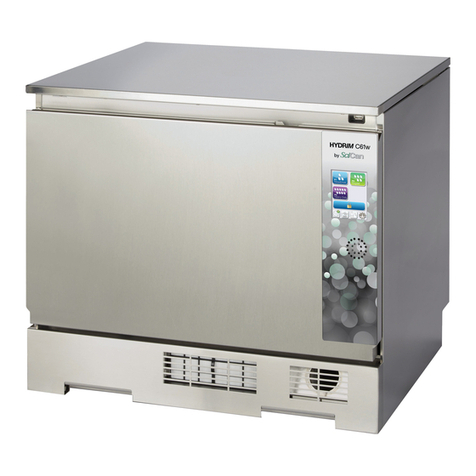
SciCan Hydrim C61wd G4 User manual

HYDRIM C61wd G4 Installation Manual 95-113166 Rev. 1.0 Copyright 2013 SciCan Ltd . All rights reserved.
HYDRim C61wd G4
INSTRUMENT WASHER
• Installation Manual and Preventative Maintenance Schedule
• Manuel d’installation et calendrier d’entretien préventif
• Installationshandbuch mit Wartungsinformationen und - intervallen
• Manuale di installazione e programma di manutenzione preventiva
• Manual de instalación y programa de mantenimiento preventivo

Environmental requirements ........................................................ 3
Unit installation checklist .............................................................. 4
Unit installation ............................................................................. 4
Installation configurations ............................................................ 4
Set up ........................................................................................... 6
Checking water quality ............................................................... 10
Connecting to a network ............................................................ 11
Connecting to a wireless network .............................................. 11
Testing the unit ........................................................................... 12
Performance Testing the unit ..................................................... 12
User training ............................................................................... 13
Unit handover ............................................................................. 14
Annual Service Requirements .................................................... 15
HYDRIM and STATIM are registered trademarks of SciCan Ltd. BRAVO, HIP,
and SysTM are trademarks of SciCan Ltd. All other trademarks referred to
in this manual are the property of their respective owners.
For all service and repair inquiries:
In Canada 1-800-870-7777
United States: 1-800-572-1211
Germany: +49 (0)7561 98343 - 0
International: (416) 446-4500
Email: [email protected]
Manufactured by:
SciCan
1440 Don Mills Road,
Toronto ON M3B 3P9
CANADA
Phone: (416) 445-1600
Fax: (416) 445-2727
Toll free: 1-800-667-7733
EU Representative
SciCan GmbH
Wangener Strasse 78
88299 Leutkirch GERMANY
Tel.: +49 (0)7561 98343 - 0
Fax: +49 (0)7561 98343 - 699
SciCan Medtech
Alpenstrasse 16
CH-6300 ZUG SWITZERLAND
Phone: +41 (0) 41 727 7027
Fax: +41 (0) 41 727 7029
HYDRIM C61wd G4 Installation Instructions

NOTE:
• TheHYDRIM C61wd G4 unit should only be installed by a trained, SciCan approved
technician.
• Installationshouldonlyproceedafterthesatisfactorycompletionofthepreinstallation
documentation.
Model Number________________________ Serial no.____________________
There are several factors that may affect the performance of your HYDRIM. Please review
these factors, before installation and ensure the location is suitable.
Temperature and Humidity
Avoid installing your HYDRIM in direct sunlight or close to a heat source (e.g. vents or
radiators). The recommended operating temperatures are +5 to +40°C with humidity of 80%
for temperatures up to 31°C and 50% for temperatures up to 40°C.
Spacing
The vents and openings on the HYDRIM should remain uncovered and unobstructed. Do not
move the HYDRIM C61wd G4 into place by maneuvering the open wash chamber door. This
may cause the door to become misaligned and can cause leakage.
Venting
The HYDRIM should be operated in a clean, dust free environment.
Work Surface
The HYDRIM should be placed on a flat, level, water-resistant surface. Never install and
operate the unit on a sloped surface.
Electromagnetic Environment
The HYDRIM has been tested and meets applicable standards for electromagnetic
emissions. While the unit does not emit any radiation, it may itself be affected by other
equipment which does. We recommend that the unit be kept away from potential sources
of interference.
Electrical Requirements
Use properly grounded and fused power sources with the same voltage rating as
indicated on the label at the back of your HYDRIM. Avoid multiple outlet receptacles. If using
a surge suppressor power bar, plug in one HYDRIM only.
WARNING: NEVER LOCATE THE HYDRIM WITH THE ELECTRICAL
OUTLET RECEPTACLE BEHIND THE MACHINE!
Page 3
HYDRIM C61wd G4 Installation Instructions

Page 4
HYDRIM C61wd G4 Installation Instructions
Unit installation checklist
NOTE: Refer to Operator’s manual during installation for operating the machine.
1. Inventory Check
Open box and check contents (add or as appropriate):
HYDRIM C61wd G4 unit
Operators manual
Carrier (trolley)
Cleaning solution carrier (installed in unit)
Water feed hose (red) – ‘hot’
Water feed hose (blue) – ‘cold’
Drain tube
Drain tube clips (x2)
Water hardness test kit
Salt for regeneration unit
Salt funnel
HEPA Filter (installed in unit)
NOTE: Additional racks/baskets will be needed to run the unit with instruments. Please refer
to the Operator’s Manual for different configurations.
NOTE! HIP™ Ultra cleaning solution (CS-HIPC-U) is required to run the machine and is NOT
included with the machine. Please ensure cleaning solution has been separately provided
prior to installation.
2. Unit installation
Installation configurations
The HYDRIM C61wd G4 may be installed under-bench or free standing dependent on space
and service availability.
The configuration options are:
Option 1. Cabinet / Sterilization Center

Page 5
HYDRIM C61wd G4 Installation Instructions
Option 2. Sliding Shelf
Option 3. Counter Top
NOTE 1 - Although not required, if the HYDRIM is installed under a counter, it is
recommended to allow a 10 mm space at the top, back and both sides of the unit.
This will facilitate installation, levelling, and service access to the HYDRIM.
NOTE 2 - Important! Ventilation during drying is via the front of the machine. Some increase
in humidity may be apparent during this drying phase and it is imperative that sufficient air
circulation is available surrounding the machine to enable this humidity to be dissipated.
Failure to provide adequate ventilation may lead to equipment or cabinetry damage
(depending on installation configuration).
NOTE 3 - The drying system has a filtered air intake. The free movement of air to this intake
is important and failure to provide the required space may cause overheating of the dryer
motor and/or compromise drying efficiency.

Page 6
HYDRIM C61wd G4 Installation Instructions
Set up unit as follows:
• Unpackunitandremoveallrestrainingties
• Locateunitinapproximateposition
NOTE 1 - Do not move the HYDRIM C61wd G4 into place by maneuvering the open wash
chamber door. This may cause the door to become misaligned and can cause leakage.
n
1 Power switch
n
1 Kickplate
n
1 Bacteriological air filter
1n
1 (if fitted)
n
1 HEPA filter
n
1 Dryer exhaust
n
1 Door latch
n
1
n
1 USB port
n
1 LCD touchscreen
n
1 Dryer outlet
n
1 Water softener
n
1 Wash arms (top not shown)
n
1 Coarse filter
n
1 Cleaning solution
n
1 and drawer
n
1 Drain outlet
n
1 Ethernet port
n
1 RS232 port
n
1 Cold water inlet
n
1 Hot water inlet
n
1 R/O water inlet
n
1 Fuses
n
1 Power cable connection
n
1 Drain tube (behind kickplate)
2
Rear Connections
1
2
3
4
5
6
14
15
16
17
18
19
7
8
9
10
11
12
2
13
2 926 28
1 2 4 5
2118 19
15 17 2014
7
20
21
22
11 12
13
3
10
16
22

Page 7
HYDRIM C61wd G4 Installation Instructions
Connect water feed pipes to machine and relevant services:
Water feed requirements:
Hot water/RO feed with G ¾” shut off valve
(washing machine fitting)
• Maximum distance from installation less
than 1.50 meters
• Pressurebetween2and5bar
Cold water feed with G ¾” shut off valve
(washing machine fitting)
• Maximumdistancefrominstallationless
than 1.50 meters
• Pressurebetween2and5bar
Reverse Osmosis water feed with G ¾”
shut off valve (washing machine fitting)
• Maximumdistancefrominstallationless
than 1.50 meters
• Pressurebetween2and5bar
Connecting the water inlet hoses (see diagram):
Connect the hot water hose (red) to the hot water inlet valve (18) on the HYDRIM
(indicated by a red dot) and the cold water hose (blue) to the cold water inlet valve (17) on
the HYDRIM (indicated by a blue dot). Treated water from a reverse osmosis system can be
connected to the R/O inlet (19). If fitted with treated water, the software must be adjusted to
enable the function of the R/O inlet. The connector with the elbow should be attached to the
drain outlet (14) on the back of the HYDRIM unit. The end of the hose with the gasket and
the screen should attach to the water supply connector. Make sure that the inlet valves are
free of debris (17, 18 & 19).
NOTE 1 - If hot water feed is not available then it must be possible to attach a ‘Y’ fitting to
the cold water feed valve so that both machine pipes can be connected to the cold
supply. The machine will not work with only one supply attached as it requires pressure
in both the hot and cold water supplies to activate the feed pressure switches. If R/O
water is not enabled, the R/O supply does NOT need an attachment. Please note that
cold fill only will increase cycle times.
NOTE 2 – Water feeds should be adjacent to the machine and not behind it so that the shut
off valves may be accessed in case emergency isolation is required and to ensure unit can
be inserted fully under the work surface.

Page 8
HYDRIM C61wd G4 Installation Instructions
Connect drain tube to machine and relevant services
Drain requirements:
• Maximumdistancefrominstallationis1.50
meters with supplied drain hose
• Themaximumlengthofanextendeddrain
hose should not exceed 3.30 meters
• Drainshouldbenomorethan1meter
above the base of the HYDRIM unit
• ‘P’trapspurconnection(preferred
method) OR
• Standpipeconnection
NOTE 1 – The preferred method of connection of the HYDRIM to the drain is by the use of a
‘spurred’ ‘P’ trap fitting.
NOTE 2 – The waste connection pipe is clamped on to the spur by the clips provided with
the HYDRIM. Wherever possible, if the HYDRIM is located close to a sink unit, then this
method should be used. If the HYDRIM is not close to a sink unit and a ‘P’ trap cannot be
used, then a standpipe with ‘U’ bend fitting can be used. This must be a dedicated
standpipe. Under no circumstances should any other equipment share the standpipe.
NOTE 3 – Waste connection should be adjacent to the machine and not behind it.
Connecting the drain hose:
Connect the drain hose to the drain outlet. The drain hose can be attached to existing drain
lines using a 3.5 cm or larger standpipe/ P-trap combination. If the hose is connected
directly to the drain line, fittings and adapters should not reduce water flow. A floor drain is
acceptable (check local codes).
Level machine in final position with adjustable legs
For the unit to function properly, it will need to be correctly leveled. To level the unit, follow
these steps:
1. Adjust the legs underneath the unit.
2. Use a level as a guide

Page 9
HYDRIM C61wd G4 Installation Instructions
Connect machine to power supply
Electrical supply requirements:
• Dedicated12Aindependentsupply(see
Note 1 below). OR
• Standarddomesticoutlet
• Voltage:200-240VAC±10%,single-phase,
50 Hz or 60 Hz, 12A
• Locatedwithin1.50metresmaximum
• Supplylocation(seenotesbelow)
• Powercordrouting(seenotebelow)
NOTE 1 – The HYDRIM C61wd G4 is supplied with a domestic fused plug as standard.
A dedicated hard wired 12A supply can also be used.
NOTE 2 - Due to the power requirements of the HYDRIM, (Rated load 2 kW) especially
during drying, it is advised that no other equipment is connected to the same supply outlet.
NOTE 3 - Power supply outlet should be adjacent to the machine and not behind it.
The cable should be routed away from the back panel and hot water inlet hose.
Other manuals for Hydrim C61wd G4
1
Table of contents
Other SciCan Washer manuals

SciCan
SciCan HYDRIM L110w G4 User manual
SciCan
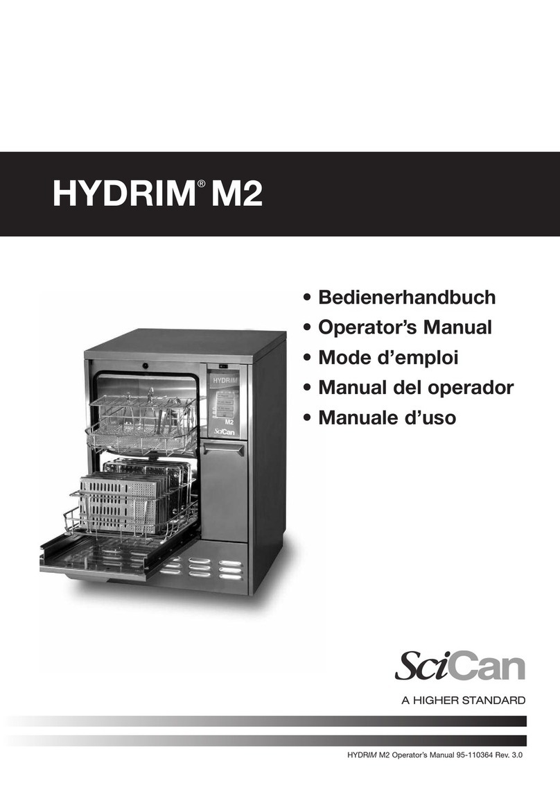
SciCan HYDRIM M2 User manual

SciCan
SciCan hydrim c51w User manual
SciCan
SciCan HYDRIM L110w User manual

SciCan
SciCan HYDRIM L110w User manual
SciCan
SciCan HYDRIM L110 G4 Series User manual
SciCan
SciCan HYDRIM L110w G4 User manual

SciCan
SciCan HYDRIM L110w User manual
SciCan
SciCan HYDRIM M2 User manual

SciCan
SciCan HYDRIM M2 G4 User manual
