SciCan HYDRIM C15wd User manual
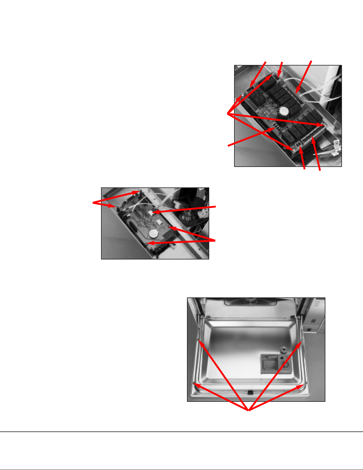
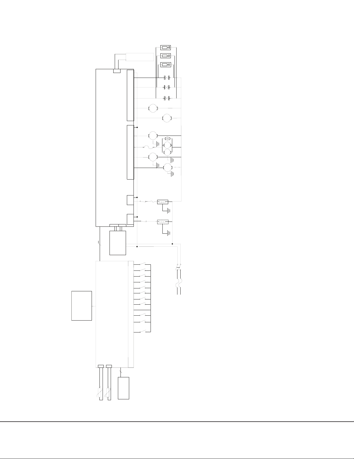
www.scican.com
• Service Manual
HYDRIM C51wd Service Manual 95-109724 Rev. 3.0
HYDRIM®C51wd

Page 1
HYDRIM C51wd Service Guide
Manufactured by:
SciCan Ltd.
1440 Don Mills Road,
Toronto ON M3B 3P9
CANADA
Phone: (416) 445-1600
Fax: (416) 445-2727
Toll free: 1-800-667-7733
SciCan GmbH
Kurzes Geländ 10
D-86156 Augsburg
GERMANY
Phone: +49 (0) 821 56 74 56-0
Fax: +49 (0) 821 56 74 56-99
For all service and repair inquiries:
Canada: 1-800-870-7777
EU: +49 (0) 821 56 74 56-0
International: 1-416-445-1600
United States: 1-800-572-1211
Email: [email protected]
Copyright 2006 SciCan Ltd. All rights reserved.
HYDRIM is a registered trademark of SciCan Ltd.
0123
Table of Contents
1. Introduction ..................................... Page 2
1.1 Overview
1.2 Specifications
1.3 Safety Information
1.4 Tools & Hardware
1.5 Shipping Instructions
2. Installation ........................................Page 6
2.1 Pre-Installation
2.2 Tools and Supplies Required
2.3 Installation Options
2.4 Connecting The Water Inlet Hoses
2.5 Drain Requirements
2.6 Levelling the Hydrim
2.7 Installing Cleaning Solution
2.8 Setting Water Softener
2.9 Installation Test
2.10 Printer / USB Setup
3. Routine Maintenance ..................... Page 12
3.1 Filter Maintenance
3.2 Wash Arm Maintenance
3.3 Test Probe Port
4. Unit Overview ..................................Page 13
4.1 The Unit At A Glance
4.2 Removing The Top Cover
4.3 Removing The Bottom Pan and Kickplate
4.4 Removing The Chemical Bracket
4.5 Removing The Controller
4.6 Removing The Door Fascia
5. Electrical Schematic .......................Page 18
6. Technical Service Menu .................Page 19
7. Troubleshooting ..............................Page 22
7.1 Cycle Faults
7.2 Troubleshooting Tools
7.3 Additional Troubleshooting
8. Spare Parts......................................Page 31
11. Appendix........................................ Page 38
11.1 Additional Information For The C51wd-LCS Model
11.2 Attaching Handpieces To The LCS
11.3 Changing the LCS Water Filter
11.4 Changing the LCS Air Supply Filter (Biological)
11.5 Changing the Air / Water Feed Lines
11.6 Removing the Solenoid
SciCan Medtech
Alpenstrasse 16,
6300 Zug
SWITZERLAND
Phone: (41-41) 727-70-27
Fax: (41-41) 727-70-29

Page 2 HYDRIM C51wd Service Guide
1. Introduction
1.1 Overview
This guide provides instructions for the servicing and repair of the Hydrim®C51wd
Instrument Washer-Disinfector. Every attempt has been made to provide accurate,
detailed instructions.
All servicing of the Hydrim C51wd should be done by certified personnel only. All local,
provincial, state and national regulations regarding the servicing of the class of device and
safety requirements must be observed.
Do not permit any person other than certified personnel to supply parts for, service, or
maintain a Hydrim C51wd. SciCan shall not be liable for incidental, special or
consequential damages caused by any maintenance or services performed on the
Hydrim C51wd by a third party, including lost profits, any commercial loss, economic loss,
or loss arising from personal injury.
The Hydrim C51wd Instrument Washer-Disinfector should only be installed and serviced
by a qualified contractor as it is an Installation Category 2 device. The contractor should
be experienced in installing equipment that requires electrical hook-up as well as
plumbing.
Hydrim C51wd Cycle Description Chart
** Cycle times depend on the temperature of incoming water.
Regular Cycle Heavy Duty Heavy Duty Cycle
Cycle with Disinfection
Description Use for moderately Use for heavily Use for heavily soiled
soiled loose soiled instruments instruments and
instruments and cassette loads cassette loads
Cold Prewash <45ºC <45ºC <45ºC
Wash 50ºC 50ºC 50ºC
5 minutes 9 minutes 9 minutes
Rinse/Disinfect 60ºC 60ºC 80ºC for 10 minutes
Dry 0-15 min. 0-15 min. 0-15 min.
Total Time** 19 minutes 23 minutes 45 minutes
without drying
Water 13 L 13L 13L
Consumption

Height: 475 mm
Width: 600 mm
Depth: 460 mm
Depth with door open: 780 mm
Weight: 35 kg
Running Noise: 60 dB(A)
Hot water connection: 50-70˚C
Water softener: 0.5 kg salt capacity
Filling system: 3.5 L safety maximum
Dryer Heater 1kW
Wash temperature: 50˚C + / - 5˚C
Electrical Rating: 220 - 240V 50 Hz 10 A
Equipment pollution degree: Pollution Degree 2
Equipment
Installation Category: Installation Category II
Maximum relative humidity: 80% for temperatures up to 31˚C
50% for temperatures up to 40˚C
Operating temperature range: - 5˚C to 40˚C
Maximum altitude: 2000 m
Mains supply: + / - 10% of nominal
Page 3
HYDRIM C51wd Service Guide
1. Introduction
1.2 Specifications
Pay close attention to the following symbols that appear in this book.
Caution, a potential
hazard to the operator
Asituation which may lead
to a mechanical failure
Important information
Pay close attention to the following symbols that appear on the unit:
Caution,
hot surface
Caution, a potential
hazard to the operator

Page 4 HYDRIM C51wd Service Guide
Safe servicing
• The Hydrim C51wd Instrument Washer-Disinfector should only be installed
and serviced by a qualified contractor as it is an Installation Category 2 device.
SciCan shall not be liable for incidental, special or consequential damages
caused by any maintenance or services performed on the Hydrim C51wd by a
third party or for the use of equipment or parts manufactured by a third party,
including lost profits, any commercial loss, economic loss, or loss arising from
personal injury.
•All local, regional, state, and national regulations regarding the servicing of this
class of device and safety requirements must be observed.
When the cover is removed:
• Hazardous voltages are accessible. Disconnect the power cord before
removing the cover.
• Sharp metal edges are exposed. Be careful, and wear long sleeves and gloves.
Power main
• A dielectric strength test (hi-pot) must be performed on the unit if parts
associated with the power main are serviced or replaced.
Ground
• A protective bonding impedance test (ground continuity) must be performed on the
unit if components of the protective earthing system are changed or if connections
are broken and remade.
1. Introduction
1.3 Safety Information
Safe operation
The following apply to both operators and service technicians:
• Exercise caution and seek assistance when lifting or carrying the unit.
• Cleaning solutions may irritate. Avoid contact with eyes, skin, and mouth.
• Never lean on the open door. The unit may tip forward causing injury.
• Always turn the unit OFF before adding softener salt or solutions. Before
performing routine maintenance or servicing the unit, turn the unit OFF and unplug
the power cord from the power source.
• The operator should never remove the cover of the unit or insert objects through
holes or openings in the cabinetry. Doing so may damage the unit and/or pose a
hazard to the operator.
• If the unit is used in a manner other than that specified, the protection provided by
the equipment may be impaired.

Page 5
HYDRIM C51wd Service Guide
1. Introduction
1.4 Tools & Hardware
The unit contains the following types of hardware:
• Phillips pan head self-tapping metal screws
• Phillips flat head stainless steel machine screws
• Torx pan head machine screws
• Torx pan head plastite screws
1.5 Shipping Instructions
The unit should be serviced on site. If it is necessary to send the unit back to the dealer,
follow these instructions. Before shipping the unit, run the drain pump to remove most of
the water from the system. If there is standing water in the chamber, siphon or ladle as
much water as possible and use an absorbent cloth to remove the rest.
Disconnect and remove the cleaning solution container and then drain the dosing
reservoir. Completely screw in the levelling legs. Specify upright, heated, and insured
shipping.
DESCRIPTION
1. Nose pliers
2. Screwdriver PH1
3. Screwdriver PH2
4. Screwdriver Slot
5. T20 Torxdriver
6. Dental Wedge
7. Wire stripper
DESCRIPTION
8. Wire cutter
9. Small screwdriver
10. Nut driver 1/4"
11. Nut driver 5.5 mm
12. Nut driver 7 mm
13. Nut driver 8 mm
14. Nut driver 13 mm
DESCRIPTION
15. Wrench 7/16"
16. Wrench 1/4"
17. 11 /16"socket
18. Allen key 2.5 mm
19. Mallet
20. Tension Gun
Reporting
• It is vital for SciCan to learn of any problem in the field. This information will help
SciCan solve the problem quickly and improve product reliability in new units.
Biological waste
• Waste water in the unit may contain biological contaminants; use a mechanical
means to siphon the contents. Wear disposable rubber gloves. Dispose of
absorbent material according to biological waste disposal regulations.

Page 6 HYDRIM C51wd Service Guide
2.1 Pre-Installation
The machine must be installed and levelled correctly for the unit to function as described.
All electrical work must be carried out by a qualified electrician and in compliance with all
local and national electrical codes.
The electrical outlet should not be located directly behind the unit. The outlet needs to be
accessible after the unit is installed. The power cord must be routed away from the back
panel and hot water inlet hose.
This appliance must be correctly grounded! The manufacturer cannot be held
responsible for damage or injury caused by incorrect or missing grounding.
• The Hydrim unit is heavy (35 kg). Exercise caution and obtain assistance when
moving it.
• The Hydrim is equipped with an air gap / anti-suction device to prevent backflow of
dirty water into the water supply. No other air gap device is necessary.
• If you need to extend the water inlet and drain hoses,ensure that you use commercial
grade plumbing hose. The maximum length of the drain hose is 3.3 m.
2.2 Tools and Supplies Required to Install the Hydrim
• Slot screwdriver • Channellocks
Ensure that HIP Cleaning Solution (instrument wash chemical) is available. All other
supplies are included with the Hydrim unit.
Voltage: 220 - 240 V
Frequency: 50 Hz
Rated load:2kW
Circuit breaker: 10 A per phase
2. Installation

Page 7
HYDRIM C51wd Service Guide
2. Installation
2.3 Installation Options
Ensure that there is a 75mm space at the top, rear and both sides of the Hydrim. This will
facilitate installation, levelling, service access and air exhaust from the rear of the unit. Do
not locate the electrical outlet directly behind the Hydrim, as this is where warm, moist air
from the chamber is exhausted. Do not move the Hydrim into place by maneuvering the
open wash chamber door. This may cause to door to become misaligned and leak.
Installation Option #1
Cabinet / Steri-Centre
Installation Option #2
Sliding Shelf
Figure 1
Figure 2

Page 8 HYDRIM C51wd Service Guide
Installation Option #3
Counter Top
2.4 Connecting The Water Inlet Hoses
Connect the hot water hose (red) to
the hot inlet valve on the Hydrim
(indicated by a red dot) and the cold
water hose (blue) to the cold water
inlet valve on the Hydrim (indicated
by a blue dot).
The connector with the elbow
should be attached to the back of
the Hydrim unit.
The washer with the screen goes
to the water supply connector.
Make sure that the inlet valves are
free of debris.
2. Installation
drain hose
outlet cold water inlet hot water inlet
Hose / Cord Length / Diameter Max. Distance from
inlet / drain
Water Pressure
(optimal)* Shut-Off Valve
Hot Inlet 1.9 m / G3/4" 1.5 m 1-10 bar Yes
Cold Inlet 1.9 m / G3/4" 1.5 m 1-10 bar Yes
Drain 1.5 m / 3/4" 3.3m — —
Electrical 1.8 m
AWG 18-3 — — —
*unit will function with water pressure down to 0.5 bar.
Figure 3
Figure 4

Page 9
HYDRIM C51wd Service Guide
2.5 Drain Requirements
Connect the drain hose to the drain outlet. The drain hose can be attached to existing
drain lines using a 3.5 cm or larger standpipe / P-trap combination. If the hose is
connected directly to the drain line, fittings and adapters should not reduce water flow.
The drain hose should be attached to the main drain at a point no more than 1 metre.
above the base of the Hydrim. A floor drain is acceptable (check local codes).
2.6 Levelling the Hydrim
For the unit to function properly, it will need to
be correctly levelled. To level the unit, follow
these steps:
1. Adjust the legs underneath the unit.
2. Use the levelling bubble on the top right hand
side as a guide.
3. When the bubble is in the centre, the unit is
correctly levelled.
2.7 Installing Cleaning Solution
Ensure that the quick-disconnect cap on the HIP Hydrim Cleaning Solution bottle is tight.
Install the bottle, and loosen the screw cap slightly (see Step 4) to prevent formation of a
vacuum in the bottle.
2. Installation
levelling bubble
Figure 5
Figure 6
screw cap
quick disconnect cap
MAX
MIN
Step 1 Step 2 Step 3 Step 4

Page 10 HYDRIM C51wd Service Guide
2. Installation
2.8 Setting the Water Softener (salt):
Hydrim is equipped with a built-in water softening system which needs to be
adjusted according to the local water hardness. The Hydrim water test kit
includes three water hardness test strips in bags. Take a water sample from
the location where the machine will be installed. Open one of the bags and
remove the test strip. Dip the strip in the water. Compare the color of the
strip with the chart on the back of the bag. Determine the water hardness
according to the chart on the water test kit envelope. Power the unit on.
Touch the “i” in the lower right hand corner of the sceen. Select
“Technician”. Enter 7919 and touch EN. Select “Cycle Settings" and then
"Set Regeneration”. Using the up and down arrows, set the water softener
regeneration level according to the following table:
Pour 0.5 litre of water into the water
softener by pouring it into the salt
container and inserting it into the
chamber wall. Add 0.5 kg of water
softening salt in the same manner.
Screw the salt container tightly into
the wall of the chamber.
2.9 Installation Test
Turn on the shut-off valves. Run a test cycle, checking for leaks.
water softener
container
Hardness – ppm Hydrim setting
0 - 110 0
120 - 360 1
370 - 510 2
520 - 890* 3
> 890 Additional water
treatment required
*consider using an additional water treatment
Figure 7

2.10 Printer / USB Setup
The Hydrim C51wd has an RS-232 port at the back, and can be used with an external
printer or the SciCan Data Logger. The printers in the chart below have been tested
with the Hydrim. To add or change a printer or SciCan Data Logger, follow these steps:
Turn off the Hydrim and the printer or Data Logger before connecting these devices to
the unit.
1. With the printer or Data Logger connected, turn on the Hydrim and press the ito
move to the Menu screen.
2. In the Setup menu, select Printer Selection.
3. Select Serial Printer if connecting a printer, or USB Flash/MSD if connecting the
SciCan Data Logger. Press the back arrow to return to the Setup Menu.
4. In the Setup Menu, select Baud rate.
5. Select the rate required (refer to chart below for recommended Baud rates). Use the
back arrow to return to the Start screen.
6. Now the Hydrim will write its cycle information to the device chosen.
Printer Model Serial Port
Baud Rate
Epson
TM-U220D (C31C515603) 9600
Citizen
IDP-3110-40 RF 230B 9600
Star Micro
SP212FD42-230 9600
Star Micro
SP216FD41-230 9600
Star Micro
SP512MD42-R 9600
SciCan Data Logger Serial Port
Baud Rate
For Mass Storage Device 9600
2. Installation
Page 11
HYDRIM C51wd Service Guide

3. Routine Maintenance
3.1 Filter Maintenance
Inspect the coarse and fine filters daily for debris and clean if necessary.
1. Grasp the handle in the centre of the coarse
filter and turn it 90˚ counter-clockwise. (To re-insert
the coarse filter, turn the handle clockwise.)
2. Remove the coarse filter.
3. Remove the fine filter.
4. Clean both filters by rinsing them with tap water.
5. Re-assemble, ensuring that the
coarse filter is locked in place.
3.2 Wash Arm Maintenance
Inspect the wash arms weekly for debris and
clean if necessary.
1. Open the unit door and remove the
wash rack from the unit.
2. Unscrew the upper wash arm plug by turning
the fitting at the hub (note: fitting is left
threaded).
3. Remove the upper wash arm.
4. Using two hands, grasp both ends of the
lower wash arm on the underside.
5. Pull the lower wash arm upwards.
6. Inspect both sides of the wash arms for
debris in the nozzles. Remove the debris
where necessary.
7. Rinse both wash arms with tap water and
re-assemble the wash arms.
3.3 Test Probe Port
A technician or authorised person can use the test port to insert
temperature probes into the chamber to record the actual
temperature at various places in the chamber during the cycle.
To access the temperature probe port, remove the
front fascia (see section 4.6).
coarse filter
fine filter
upper wash arm
fitting
lower
wash arm
lower wash
arm collar
To remove arm, pull upwards
Figure 8
Figure 9
Figure 10
Figure 11
port
Page 12 HYDRIM C51wd Service Guide

4. Unit Overview
heater (18)
drain
Pump
(9)
float
temperature
switch (46)
capacitor
temper-
ature
sensor
(54)
Top View
Left Side
Right Side
low circulation
pump pressure
switch (safety) (19)
4.1 The Unit At A Glance
dryer (42)
dosing pump (4)
air filter (47)
dosing
reservoir (28)
heater
(18)
lower
circulation
pump (7)
water
softener
door
solenoid (62)
dryer duct
(39)
top arm
fitting (65)
Tubing,
top arm
fitting
(64)
door
lock
level
sensor
valves
(hot and
cold)
(12, 22)
upper
circulation
pump (8)
drain
connection water
softener
Figure 12
Figure 13
Figure 14
Figure 15
Bottom View
quick
connect
(25)
manual
door
release
(53)
chemical
tube
(33) drip tray (27)
Page 13
HYDRIM C51wd Service Guide

4.2 Removing The Top Cover
To remove the top cover, follow
these steps:
1. Power OFF the unit, and
unplug.
2. Remove the 4 Phillips
screws that hold the filter
cover in place (Figure 16a).
3. Remove the screws that
secure the top cover:
• 2 screws and white caps on
the right side of the cover (Figure 16a).
• 2 screws and white caps on the left of
the cover (not shown).
• 7 Phillips washer screws on the back
of the cover: (1 on the top, 3 on the right,
3 on the left.) (Figure 16b)
• 6 Phillips flat head machine screws
on the inside front of the unit (4 on the
top, 2 on the left) (Figure 16c). The two
screws on the right side do not secure
the top cover and do not need to be
removed.
4. Grasp the left and right sides of the cover.
Pull sides slighty outward and lift straight up.
5. Remove the insulation on the top and sides.
6. When replacing the cover, ensure that the orange cap for the screw under the drip
tray is replaced (Figure 16d).
4. Unit Overview
Rear Of The Unit
7 Phillips screws
6 Phillips screws
4 filter
cover
screws
2 screws
and
caps
Figure 16a
Figure 16b
orange cap
Figure 16dFigure 16c
Page 14 HYDRIM C51wd Service Guide

4. Unit Overview
4.3 Removing the Bottom Pan and
Kickplate
1. Completely open the front door.
2. Remove the two Torx screws from
the kick plate and pull the kick plate
forward to remove (Figure 17a).
3. Drain water from the unit and drain
the chemical from the reservoir.
4. Turn the unit upside down. Please
note that some liquid will remain.
5. Remove one Phillips and one Torx screw
from the bottom of the chemical bracket
(Figure 17b).
6. Remove the two Phillips screws connecting
the back panel to the bottom pan (not shown).
7. Remove four Torx screws keeping the bottom
pan in place (not shown).
8. Remove the bottom pan. Caution! Edges
are sharp.
9. Be careful not to damage the bottom pan
overflow float and make sure it is in place
before reinstalling bottom pan.
4.4 Removing the Chemical Bracket
1. Power the unit OFF.
2. Remove the top cover.
3. Remove the Phillips screws as shown (Figure 17b).
4. Remove the three screws in the backpanel
holding the chemical bracket.
5. Remove the screw on top of the
door bracket (Figure 17c).
6. Pull chemical bracket away
from the machine, loosen clip
and disconnect the dryer hose.
7. This provides access to the
pressure switch for the upper
arm, chamber full switch (black)
and the overflow switch (clear)
(Figure 17d).
Screw
Screw
Screw
Screw
Screw
Torx Screw
Torx screws
Figure 17a
Figure 17b
Door Bracket Screw
chamber
full switch
overflow switch
pressure switch
Figure 17c
Figure 17d
Page 15
HYDRIM C51wd Service Guide

4. Unit Overview
4.5 Removing the Controller Assembly
1. Remove the top cover.
2. Remove the two screws on the left
of the chemical bracket and the
screw on top that holds the bracket to
the door latch bar (Figure 18a and b).
3. Remove the two screws that hold the
fascia to the chamber (Figure 18c).
4. Pull chemical bracket away and swing
fasica out as shown (Figure 18d).
5. Access the controller assembly and
disconnect the following connectors from
the i/o board:
J6 – one 4-pin connector
J3 and J5 – two 6-pin connectors
J2 and J1 – two 2-pin connectors
J7 – one 2-pin connector
Figure 18d
Figure 18a
Figure 18b
Figure 18c
Page 16 HYDRIM C51wd Service Guide
J6
J5
J2 J1
J3
J7
Figure 18e signal
connector
screws
screws
screw
1
2

4.6 Removing The Door Fascia
To remove the door fascia, follow
these steps:
1. Power OFF the unit and unplug.
2. Open the door and remove
the 4 Phillips screws on the
perimeter of the door’s
inside face.
3. Pull the door fascia towards
you and lift up.
4. Unit Overview
screws
Figure 19
Page 17
HYDRIM C51wd Service Guide
J6
J5
J2 J1
J3
J7
Figure 18f
Figure 18g
screws
screws
standoffs printer
cable
6. Disconnect the signal connector from the
bottom of the logic board (Figure 18e).
7. Unclip the temperature sensor junction
block (not shown).
8. Remove four screws (Figure 18f)
and lift I/O board off.
9. Disconnect the printer cable from the
side of the logic board (Figure 18g).
10. To remove logic board, remove upper
standoffs and two screws (Figure 18g).
11. Reassemble in reverse order.

5. Electrical Schematic
Page 18 HYDRIM C51wd Service Guide
Y2 Y1
B1
B3
M1a M2
R1
M3
M5
M4
B7 B2
B4
B12
B6
B8
T2
Y3
Y1 - Cold water valve
Y2 - Hot water valve
Y3 - Salt valve
M1a - Circulation pump 1
M1b - Circulation pump 2 (Hydrim C51 only)
M1F - Fan (Hydrim C51 only)
M2 - Waste pump
M3 - Dryer motor
M4 - Dosing pump 1
M5 - Distribution Valve Motor (Eschmann Plus only)
AS1 - Air Solenoid Valve (Hydrim C51wd LCS & Eschmann Plus only)
B1 - Pressure switch
B2 - Chamber full switch
B3 - Chamber overflow switch
B4 - Door switch
B5 - Low salt switch (Hydrim L110 only)
B6 - Chemical 1 flow switch
B7 - Handpiece present switch (Hydrim C51wd LCS & Eschmann Plus only)
B8 - Low rinse-aid (chemical 3) switch (Hydrim L110 only)
B9 - Distribution Valve Motor Switch (Eschmann Plus only)
B10 - Conductivity Switch (Hydrim L110wd only)
B11 - Handpiece water filter pressure switch (Hydrim C51wd LCS only)
B12 - Temperature cut-off switch
B13 - Dryer temperature cut-off switch
R1 - Chamber heater
R2 - Dryer heater
T1 - PT100 - Chamber temperature sensor
T2 - PT100 - Hydrim L110wd - Second chamber temperature sensor
RC1, RC2, RC3 - RC Network RCF22-220/220 Murrelektronic
- RC3 - Hydrim L110 only
F1, F2 - 10A (Hydrim C51 only)
F3 - 2A (Hydrim C51 only)
L1
N
Power
Switch
x20
1 2 3 4 5 6 7 8 9 10 11 12 13 14 15 16 17 18 19 20
T1
1 2 1 2 1 2 3 4 5 6 1 2 3 4 5 6 L
a
t
c
h
5V
5V & 24V
Power
supply
Display &
Touch
Screen
Hydrim Master Board Hydrim I/O Board
RS232-1
AS1
GND
B5
B10
R2
24V
5
Printer
connector
B11
GND
GND
J6
1
2
3
4
J1 J2
J3 J5
J7
3
2
1
3
2
1
J100
J101
J104
1
2
GND
J201
J300 J102 J4
RC2
RC1
RC3
B13
Temp.
Fuse
F1
F2
M1b
F3
M1F
B9

Service Menu Overview
6. Technical Service Menu
Cycle
Count
Diagnostic
Tools
• Error History
• Test Cycle
• Component Test
• View IO Set up
• Verify Mode
• Set debug screen
Cycle
Settings
Printer
Selection
Baud
Rate
Software
Upgrade
Factory
Default
Repeater
Mode
Production
Tools
• Set Drying Time
• Set Regeneration
• Chemical set-up
• Set Wash Time
• Set Rinse Time
• # Extra Rinses
• Set Wash Temperature
• Last Rinse Temp
To access this menu, turn the unit on. There is an "i" in the lower right hand corner of the screen for about
10 seonds. Touch the "i" to get to the menu screen. Touch Service.
Key in the password 7919 and press EN.
Within main service menu, there are eight options.
Cycle Count: Displays the number of cycles that have been run (complete and incomplete).
Diagnostic Tools: Offers a submenu of five tools.
Error History: Allows access to the last three errors.
Test Cycle: An abbreviated cycle that uses all pumps and valves.
Cannot be used to process instruments.
Component Test: Allows individual testing of the following components.
Circ. Pump M1 - ON/OFF
All Devices - ON/OFF
Latch L1 - ON/OFF
Salt Valve Y2 - ON/OFF
Dosing Pump 1 M4 - ON/OFF
Dryer Motor + Heater - ON/OFF
Hot W. Valve Y7- ON/OFF
Cold W. Valve Y1 - ON/OFF
Rinse Aid Valve ON/OFF (not used)
Waste Pump M2 - ON/OFF
Page 19
HYDRIM C51wd Service Guide
Table of contents
Other SciCan Washer manuals

SciCan
SciCan HYDRIM L110w User manual

SciCan
SciCan HYDRIM M2 G4 User manual

SciCan
SciCan HYDRIM C61w G4 User manual

SciCan
SciCan hydrim c51w Service manual

SciCan
SciCan Hydrim C61wd G4 User manual

SciCan
SciCan HYDRIM L110w User manual

SciCan
SciCan HYDRIM M2 User manual

SciCan
SciCan HYDRIM L110w G4 User manual

SciCan
SciCan HYDRIM L110w G4 User manual

SciCan
SciCan HYDRIM L110 G4 Series User manual
Popular Washer manuals by other brands

Bosch
Bosch WAX32K03BY User manual and installation instructions

ECOSAFE
ECOSAFE LV13 instruction manual

Frigidaire
Frigidaire GLTF1670A Factory parts catalog

Whirlpool
Whirlpool 3SWTW4800YQ Use and care guide

Whirlpool
Whirlpool 3363569 Use and care guide

GE
GE Profile PFWS4600LWW Owner's Manual & Installation Instructions