Scientemp 45-3.1A Specification sheet

Your Scientemp freezer has been pre-programmed at the factory and ready for use.
You only have to:
1) Plug your freezer into its own dedicated circuit and
2) Set your desired temperature on the controller
~~To set the desired set point temperature, press and hold the * button, then while holding down the * press the UP
arrow to increase the set point temperature or press the DOWN arrow to decrease the set point temperature.
When uncrating, do not discard the Dark Grey Styrofoam Sublids inside the
freezer. *The Sublids are necessary to maintain correct temperature, moisture control and economy of
operation.
Provide at least 3” of space around the freezer for ventilation. Avoid placing
the freezer in locations exposed to direct sunlight, heat registers or any other
heat source.
Alarm On/Off switch should remain in the “Off”position until the freezer
reaches desired set point temperature. When the temperature has been
reached, turn the alarm switch to the “On” position.
Cabinet should not be loaded with product until the cabinet has operated for
24 hours at the desired set point temperature.
Maintenance tips for your Scientemp Freezer:
Regularly remove any frost build up by using a plastic/wooden scraper.
Check and replace batteries on Sonalarm and Chart Recorder (if equipped) on
a regular bases.
The black finned condenser in the refrigeration compartment of the freezer,
should be cleaned of dust and debris about once a year (or more often if
freezer is located where excessive dust and dirt may occur)
~~This can be done by vacuuming carefully or by using forced air to blow the debris off.
3565 S. Adrian Hwy ~ Adrian, MI 49221-9253 ~ 1-517-263-6020 ~ fax 517-263-5492 ~ toll-free 800-968-2653
Scientemp@scientemp.com ~ www.scientemp.com
S C I E N T E M P C O R P .
Medical Freezers ~ Pharmacy Freezers ~ Culture Storage Freezers ~ Blood Storage/Blood Plasma Freezers
Adhesive Storage Freezers ~ Industrial/Manufacturing Freezers ~ Flammable and Explosion Proof Freezers

Scientemp Corp.
3565 S. Adrian Hwy
Adrian, Michigan 49221
Phone: 517-263-6020
Fax: 517-263-5492
Website: www.scientemp.com
OPERATING
AND
INSTALLATION
MANUAL
MODEL 45-3.1A
This cabinet has passed the
QUALITY CONTROL INSPECTION
and meets the high standards at Scientemp Corp.
This inspection includes the complete refrigeration
system, cabinet construction and finish.

CONTACTING FACTORY
For reference and when contacting the factory, please have
your freezer information ready:
MODEL NUMBER: ________________________
SERIAL NUMBER: ________________________
DATE SHIPPED: __________________________
PURCHASED FROM: ______________________
The Model Number and Serial Number can be found on the
data plate attached to the cabinet on the back upper left
corner.
SCIENTEMP CORP.
3565 S. ADRIAN HIGHWAY
ADRIAN, MICHIGAN
49221
TELEPHONE: 517-263-6020
FAX: 517-263-5492
Sales Contacts:
Tracy Proffitt
517-263-6020 Ext. 104
tracy@scientemp.com
Kelli Wadke
517-263-6020 Ext. 102
Web site: www.scientemp.com
IMPORTANT! Do not discard the Dark grey foam
sublids from inside the chest freezer. The sublids are
necessary to maintain correct temperature, moisture
control and economy of operation.
1. MOVING YOUR FREEZER
The refrigeration system of the cabinet is designed to
operate with the cabinet located on a flat surface. Do not
tilt the cabinet more than 30
to any side. If the cabinet
must be tilted on an angle for handling or moving purposes
allow it to sit in an upright position for at least two (2) hours
prior to starting.
2. SAFETY PRECAUTIONS
In this manual, the words WARNING and CAUTION mean
the following:
*WARNING: a potentially hazardous situation, which if not
avoided, could result in serious injury or death.
*CAUTION: a potentially hazardous situation, which if not
avoided, may result in minor or moderate injury or damage
to equipment.
Before installing, using or maintaining this product, please
be sure to read this manual carefully. Failure to follow these
instructions may cause this product to malfunction, which
could result in injury or damage.
Below are important safety precautions that apply to this
product:
•Use this product only in the manner described in the
product literature and in this manual. Before using it,
verify that this product is suitable for its intended use.
•Do not modify system components.
•The cabinet must be properly grounded in conformity
with national and local electrical codes. Never
connect the unit to overloaded power sources.
•Disconnect the unit from all power sources before
cleaning, troubleshooting or performing other
maintenance on the cabinet.
3. CHOOSING A LOCATION
3.1 Air Circulation
The cabinet should be situated to allow proper air circulation
in a well ventilated room. Provide at least 3” of space around
the freezer for ventilation. Avoid placing the freezer in
locations exposed to direct sunlight, heat registers or any
other heat sources.
*NOTE: The cabinet must be installed on a sturdy, solid,
level floor resting firmly on all four mounting points.
3.2 Ambient Temperature
Do not place cabinet in sunlight, near heating diffusers,
radiators or other sources of heat. Drafts from fans, air
conditioning or open doors can also affect the product
temperature. The ambient temperature range at the location
must be 59 to 90F (15 to 32C).
*Warning: This unit is not a “rapid-freeze” device.
Freezing large quantities of liquid or high water content
items will temporarily increase the compressors to operate
for prolonged periods of time. Attempting to utilize this
Before you get started, please take a few minutes
to read through this manual.

freezer improperly may jeopardize safety or cause undue
stress or damage to the refrigeration compressors.
Avoid opening the door for extended periods of time since
chamber air will escape rapidly. Room air, which is higher
in humidity, will replace chamber air and may cause frost to
develop in the chamber more rapidly.
4. CHECK OUT YOUR NEW FREEZER
4.1 Lid Seal
If the lid gasket does not seal along the front edge, relieve
the compression of the gasket along the back edge by
loosening the hinge screws where they attach to the cabinet.
Raise the lid slightly and then retighten the screws.
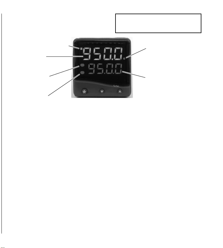
4.2 Interior Compartment Temperature
The temperature is controlled by a CAL 9500 digital
temperature controller. When you first power up the freezer,
the high stage compressor and fan will start and operate for 3
to 6 minutes before the low stage compressor starts. Pull
down to minimum temperature will take from 3 to 6 hours,
depending on ambient temperature and size of cabinet. The
high stage compressor runs 100% of the time. The low stage
compressor will cycle on and off to maintain the temperature
of the controller setting. Set the control to the desired set
point. To view the set point temperature, press the * and the
UP arrow keys together. To decrease the set point
temperature, press the * and the DOWN arrows keys
together.
Freezers are shipped from the factory with the indicating
digital control programmed for proper operation. All but the
temperature settings may be adjusted. The temperature
sensor is a type “T” thermocouple located on the front wall
of the inner-liner.
4.3 Alarm Signal System
The Alarm should be kept in the “OFF” position until the
cabinet temperature has reached the appropriate setting.
When the temperature has been reached, the temperature
alarm should be switched to the “ON” position and is now
ready to operate. It will monitor “temperature rise” and
“power-failure”. The control is factory set to operate the
alarm at approximately 10F (6C) above the set
temperature. No further adjustment is necessary unless a
spread other than this is desired. In the event a temperature
spread of more or less than factory set is desired, refer to
your digital temperature control manual.
NOTE: It is recommended to keep the freezer operating
continually rather than turning the freezer off and on.
5 ELECTRICAL CONNECTIONS
5.1 Wiring
This cabinet is equipped with a three-prong (grounding) plug
for your protection against shock hazards. The cabinet
should be plugged directly into a properly grounded three-
prong receptacle.
Where a two-prong wall receptacle is encountered, it must be
replaced in accordance with the National Electronic Code
and local codes and ordinances. A licensed electrician must
do the work.
The electrical outlet should not be controlled by a wall
switch, which might be turned off accidentally.
*WARNING: Do NOT under any circumstances cut or
remove the round grounding prong from the cabinet
plug.
*CAUTION: For personal safety and trouble-free operation,
this cabinet must be properly grounded before it is used.
Failure to ground the equipment may cause personal injury
or damage to the equipment. Always conform to the
National Electrical Code and local codes. Do not plug in the
cabinet to overloaded power lines.
Consult a licensed electrician if you have ANY doubt
about the grounding of your wall receptacle. Only a
licensed electrician can determine the polarization of
your wall receptacle.
6 DANGERS OF A LOW TEMPERATURE FREEZER
Any temperature below 0Centigrade or 32Fahrenheit
provides a potential condition to cause freezing of water or
material containing water. Material containing water
solutions of salt or sugar will freeze at a slightly lower
temperature, depending on the content of the solution.
Because all warm-blooded creatures are composed of a great
percent of water with salinity, they are subject to freezing
whenever the body cells, parts or extremities reach
temperatures below freezing.
6.1 When Skin Freezes
When your skin is exposed to subfreezing temperatures for
an extended amount of time, it can freeze. Your blood
vessels constrict in response to dropping temperatures. This
reduces the flow of blood and, therefore, the amount of
oxygen to the tissues. When water in these tissues freezes
and forms ice crystals, cell structure is destroyed.

Tissue damage from cell death interrupts circulation in the
smallest blood vessels. Blood clots form and blood flow is
further diverted away from the frozen tissue. At this point,
your skin temperature drops and the injured area grow even
colder.
The first sign of frostbite may be a slightly painful tingling
sensation, which often is followed by numbness. Your skin
may look pale, and feel hard, cold and numb.
In the event of frostbite, warming is vital. Carefully warm
frost bitten areas gradually. Place your hands directly on the
skin of warmer areas of your body. If possible, immerse
your hands in water that is slightly above normal body
temperature (about 100F or 37.8C), or which feels warm to
someone else, until your normal color returns. Do not use
direct heat. Seek medical attention as quickly as you can.
7 REFRIGERATION COMPARTMENT
The refrigeration system of a Scientemp freezer is
hermetically sealed. It requires no maintenance. However, in
areas where excessive dust and dirt collects, the condenser
must be kept clean. To clean the condenser, remove power to
freezer. Remove the guard on the back of the freezer. Use
forced air and a vacuum to clean dirt and debris from the
condenser and refrigeration compartment periodically.
7.1 Fan
The fan motor has lifetime lubrication. It requires no
maintenance.
7.2 Frost removal
1. While the freezer is running the frost may be
removed with a plastic or wooden scraper or
spatula. Do not use metal or sharp objects such as
an ice pick, as this will cause serious damage to the
finish of the inner-liner of the freezer. The frost and
ice may be collected in a pan, towel or any device to
prevent it from falling to the bottom of the freezer
or onto the material stored in the freezer. Most of
the frost and ice collects near the top edge and is
easily removed.
2. In the case where the freezer is not loaded, frost and
ice may be removed by disconnecting the power
until the frost and ice thaw. After defrosting, dry
the freezer compartment interior and plug freezer
back in.
8 ALARM SIGNAL SYSTEM
SCIENTEMP Alarm signal system is a dependable, compact
unit designed to audibly alert you for temperature rise and
power failure. The Alarm is an audible and visual signal-
warning system. It produces a penetrating, repeating sound
to alert you.
The Alarm system, used in conjunction with a SCIENTEMP
low temperature cabinet, will monitor “temperature-rise” and
“power-failure”.
1. Temperature rise and power failure is indicated by
flashing red light accompanied by a repeating
audible signal in the form of beep-beep-beep.
The Alarm system is powered by two (2) “9 volt” batteries.
It is important that the batteries be placed correctly in the
holders for the proper polarity. We recommend batteries be
replaced once a year to assure performance of the alarm.
Press the “test button” for frequent checks on battery life
and performance. If the Alarm fails to operate properly, it
may be due to a weak battery, which should be checked first.
8.1 Testing the Alarm Signal System
Switch the Alarm to the “ON” position. To simulate
“temperature-failure”, lower the set point temperature on the
controller to trigger the alarm. Once in operation, pressing
the “TEST” button checks for battery life.
*CAUTION: Wear protective clothing while either
handling or coming in contact with inside of freezer.
Hands should be dry and protected by using gloves.
Insulated gloves are best for extended use when
handling frozen product. Sleeves or arm-length
insulated gloves should protect arms. Coats,
insulated aprons, etc. should protect other parts of
the body that may be exposed to the cold.

9 REMOVING & INSTALLING CABINET LID
*CAUTION: HINGES ARE SPRING LOADED
1. Remove the two top and one-bottom screws holding
the lower portion of the hinge to the cabinet.
2. While applying pressure to hold the hinge to the
cabinet, remove the remaining bottom screw.
Carefully let the spring tension lift the hinge from the
cabinet.
3. Remove the lid from the cabinet and remove the four
screws holding the upper portion of the hinge to the
lid.
4. To reinstall the lid, reverse the above procedure.
5. Check the lid for alignment and the gasket for a
proper seal. Use the slotted hinge holes to make any
required adjustments.
10 DIGITAL TEMPERATURE CONTROLLER
REPLACEMENTS
Remove the following items in order shown:
1. Remove the instrument panel, which is held in place
by four (4) screws.
2. Remove the wires from the controller.
3. Remove the mounting brackets on the controller.
4. Remove the controller from the instrument panel.
5. Insert new controller into instrument panel,
reverse procedures. When rewiring use
enclosed wiring diagram.
11 CHANGING THERMOCOUPLE (T/C)
1. Disconnect power and let freezer warm up.
2. Remove stainless steel corner slips from front two
corners.
3. Remove white plastic breaker by pulling up and out
on edge next to inner liner.
4. Lift insulation and remove hard board sub breaker.
5. Remove instrument panel (4 screws) and lay in front
of freezer face down.
6. Remove T/C wires from terminals.
7. Remove ¾” rubber grommets from cabinet bottom &
inner liner.
8. Remove clips over T/C
9. Tape bulb of new T/C securely to control end of old
T/C.
10. From the top, reach into insulation and pull old T/C
up through insulation bringing new T/Cup with it.
11. Remove tape and old T/C.
12. Feed new T/C through ¾” hole and secure inside
inner liner the same as old T/C. Coil excess in
insulation.
13. Replace breaker, sub breaker and grommets using
reverse procedure.
14. Secure T/C wires to CAL 9500 control.
15. Reposition control panel.

INDEX INSTRUMENT PANEL FEATURES
INSTRUMENT PANEL FEATURES 2
FUNCTIONS MENU 3
GETTING STARTED 4
Initial Set-up 4
AUTOTUNE 4
Tune or tune at setpoint program 5
PROPORTIONAL CYCLE-TIME 5
Cycle-time recommendations 5
SECOND AND THIRD SETPOINTS (SP2 and SP3) 5
Error messages 6
LINEAR INPUT 6
Set-up procedure 6
FUNCTION LIST 7
Level 1 7
Level 2 7
Level 3 8
Output Options Table 8
Re-transmission 8
Level 4 9
Level A 10
PROGRAMMER 11
Function overview 11
Getting started (Programmer) 12
Program run mode 12
Display functions 12
Example program 13
Function map 14
Function list 16
Memory allocation table 17
Memory full indicator 17
Programming example 18
Program edit example 18
MECHANICAL INSTALLATION 19
DIN panel cut-out 19
Mounting 19
Cleaning 19
ELECTRICAL INSTALLATION 19
Typical application 20
Input options (diagrams) 21
Output options (diagrams) 21
INPUT SENSOR SELECTION 22
Temperature sensors 22
Linear input 22
SPECIFICATION 22
SAFETY AND WARRANTY 23
2
Right Red LED:
Program Holdback
indicator
Orange Display:
Setpoint value or
program selection
Green LED:
Setpoint 1 output indicator
Upper Red LED:
Setpoint 2 output
indicator
Lower Red LED:
Setpoint 3 output
indicator
Green Display:
Process variable or
Function/Option
ADJUSTMENTS
To enter or exit program mode: Press ▲ ▼ together for 3 seconds
To scroll through functions: Press ▲or ▼
To change levels or options: Press ✱ ▲ together or ✱ ▼ together
To view setpoint units: Press ✱
To increase setpoint: Press ✱ ▲ together
To decrease setpoint: Press ✱ ▼ together
To reset latched alarm or tune fail: Press ▲ ▼ together briefly
To run or Hold a program: Press ✱ ▼ together for 3 seconds
Notes: If in difficulty by becoming “lost” in program mode, press ▲ and ▼together for 3
seconds to return to display mode, check the INSTRUMENT ADJUSTMENTS above and
try again.
When in program mode, after 60 seconds of key inactivity the display will revert to
either
inPt : nonE
or, if the initial configuration has been completed, the measured
value. Any settings already completed will be retained. During Program Configuration it
is recommended that this feature is inhibited. Select
ProG StAY
in Level 4.
This page can be photocopied and
used as a visual aid and bookmark when
working in other parts of the manual.
!
English

Cal 9500 Configuration Data
Level 3 Level P
SP1.d – rly Prog – 1
SP2.d – rly Run - OFF
Burn – uP.SC
rEV.d – 1d.2r
rEV.L – 1i2n
SPAn – 0.0
Zero – 3 (Note: Only Change this parameter if calibrating unit, value
may vary.)
ChEk – off
rEAd - Var
tECh – CtA
Ver – 953
rSET – none
Level 2
SP1.P – 0
hAnd – off
PL.1 – 100
PL.2 – 100
SP2.A – Dv.hi
SP2.b – none
di SP – 0.1
hi .SC – 100
Lo. SC – -100
in Pt – tc t
unit – C
Level 1
tune – off
band – 0.3
int.t – off
dEr.t – off
dac – 0.5
cyc.t – on.of
ofSt – 0.0
SP.Lk – off
SPrr – 0
SPrn – off
SoAk – --
Set.2 – 6 (alarm deviation)
bnd.2 – 0.1
Cyc.2 – on.of

Standard Warranty
Applies Only Within the Continental United States
SCIENTEMP WARRANTS TO THE ORIGINAL PURCHASER
FIRST 18 MONTHS – The cabinet and all of its parts shall be free of defects in material and workmanship under
normal use and service for a period of 18 months from the date the unit has been shipped from our facility.
Scientemp’s sole obligation under this warranty shall be limited, at its option, to either repairing or replacing any
part of the cabinet determined by an authorized service agent to be defective. Scientemp reserves the right to repair
the freezer at our facilities.
THE SCIENTEMP STANDARD WARRANTY DOES NOT COVER
TRANSPORTATION COSTS – Scientemp shall not be responsible for transportation or incidental costs incurred
in connection with the repair or replacement of a cabinet or any of its parts.
ABUSE, MISUSE, ACCIDENTS – Scientemp shall not be responsible for parts or assemblies which upon
inspection are determined by an authorized Scientemp Service Agent to have been subjected to misuse, neglect,
alteration, accident, abuse, damage during transit or delivery, or by fire or flood.
CONSEQUENTIAL DAMAGES – IN NO EVENT SHALL SCIENTEMP CORP BE LIABLE FOR
SPECIAL, INDIRECT OR CONSEQUENTIAL DAMAGES, INCLUDING WITHOUT LIMITATION,
PRODUCT LOSS OR PRODUCT SPOILAGE CLAIMS, NOR FOR ANY DELAY IN THE
PERFORMANCE OF THIS WARRANTY DUE TO CAUSES BEYOND ITS CONTROL.
GENERAL
The standard warranty and any service contract related to the STANDARD WARRANTY shall apply only to the
products sold and used within the boundaries of the Continental United States.
Users may file warranty claims either directly with Scientemp Corp, 3565 S. Adrian Hwy, Adrian, MI 49221, or
with the seller from whom the cabinet was purchased. All claims must be supported by information concerning the
alleged defect and specifically identified by the Serial Number of the cabinet.
THERE ARE NO OTHER WARRANTIES EXPRESS, IMPLIED, OR STATUTORY, EXCEPT THIS
WARRANTY, WHICH IS IN LIEU OF ALL OTHER WARRANTIES INCLUDING TO THE EXTENT
PERMITTED BY LAW, ANY IMPLIED WARRANTY OR MERCHANTABILITY OR FITNESS FOR A
PARTICULAR PURPOSE.
DO NOT DRILL HOLES IN CABINET
Refrigeration tubing and wiring is routed through the cabinet walls. Leaks, wet insulation or electrical problems
caused by drilling holes are not covered by warranty.
3565 S. Adrian Hwy ♦Adrian, MI 49221
800-968-2653 ♦517-263-6020 ♦Fax 517-263-5492


17B
3
1
14
4
5
6
10
9
14
15
17A
18
13
7
19
13
8
9
16
2
12

1Outer Metal Lid Pan 5010-3.1
2Tube Style Handle 1027-3
3Hinge Assembly 1038
4Lid Insulation Call
5Lid Gasket (Includes clips not shown) 1003-3.1
6Plastic Lid Liner 1008-3.1
7Dark Grey/Black Sub Lid (Styrofoam) 1002-3.1
8Breaker Strip Length 1095-3.1-L
9Breaker Strip Width 1095-3.1-W
10 Stainless Steel Corner Cap 1098-3.1
11 Replacement Key (Not Pictured) 1031
12 Metal Sub Breaker Clip Call
13 Sub Breaker Strip Length Call
14 Sub Breaker Strip Width Call
15 Keyed Hasp Lock Assembly 1027.4
16 Cabinet Shell Call
17A Leg Assembly (Left) Call
17B Leg Assembly - (Right) Call
18 Standard Non- Locking Casters 1030-2
18 Locking Casters (Optional-Not Shown) 1030-2L
19 Interior Tank Assembly 5006-3.1
Diagram
Number
Model # 45-3.1
or 85-3.1
Part Description
Table of contents
Other Scientemp Freezer manuals